Table of Contents
Advertisement
Quick Links
Advertisement
Table of Contents

Related Manuals for Logic IO RTCU NX-200


Summary of Contents for Logic IO RTCU NX-200
- Page 1 RTCU NX-200 Advanced Automotive M2M/IoT Gateway Technical Manual Version 1.00...
-
Page 2: Introduction
NX32 applications can execute without changes. The RTCU NX-200 is designed to meet the ever-increasing challenges on security, in that it offers full TLS on all major protocols and includes a hardened protected execution environment with dual-boot and automatic fallback and recovery. - Page 3 RTCU NX-200 Technical Manual V1.00 Advanced Automotive M2MI/IoT Gateway * * * * THIS PAGE IS INTENTIONALLY LEFT BLANK * * * Logic IO ApS. Ph: (+45) 7625 0210 Holmboes Allé 14 Fax: (+45) 7625 0211 8700 Horsens Page 3 of 45 Email: support@logicio.com...
-
Page 4: Table Of Contents
RTCU NX-200 Technical Manual V1.00 Advanced Automotive M2MI/IoT Gateway Table of contents Introduction ..............................2 Important Information ............................ 6 Technical Highlights ............................7 Graphical overview: ............................9 External connections ............................. 10 Overview ..............................10 Signal Overview ............................11 Power supply ............................. 15 Digital outputs ............................ - Page 5 RTCU NX-200 Technical Manual V1.00 Advanced Automotive M2MI/IoT Gateway Appendix A – Installing the external SIM-Card ..................37 Appendix B – Installing the internal SIM-Card ..................38 Appendix C – Installing the SD-CARD ...................... 41 Appendix D - Enabling the CAN bus channel 1 write capability ............41 Appendix E - Open Source Disclaimer .......................
-
Page 6: Important Information
In the event of damage to the device caused by failure to observe the information in this manual and on the device, Logic IO Aps shall not be required to honor a warranty claim even during the warranty period and shall be exempted from the statutory accident liability obligation. -
Page 7: Technical Highlights
RTCU NX-200 Technical Manual V1.00 Advanced Automotive M2MI/IoT Gateway Technical Highlights Platform: ➢ Based on the RTCU M2M Platform. ➢ NX32L (NX32 for Linux) execution architecture. ▪ RTCU IDE development tool. ▪ Operates under a full and highly optimized Linux variant. - Page 8 RTCU NX-200 Technical Manual V1.00 Advanced Automotive M2MI/IoT Gateway User Interaction: ➢ High-speed Mini-USB service-port connector. Audio: ➢ Fully digitized audio system. ➢ Transfer, store, and play audio. ➢ Amplified speaker output. ➢ Microphone input. ➢ Digitized cellular audio. ➢ DTMF support for Interactive Voice Response applications.
-
Page 9: Graphical Overview
RTCU NX-200 Technical Manual V1.00 Advanced Automotive M2MI/IoT Gateway Graphical overview: Logic IO ApS. Ph: (+45) 7625 0210 Holmboes Allé 14 Fax: (+45) 7625 0211 8700 Horsens Page 9 of 45 Email: support@logicio.com Denmark www.logicio.com... -
Page 10: External Connections
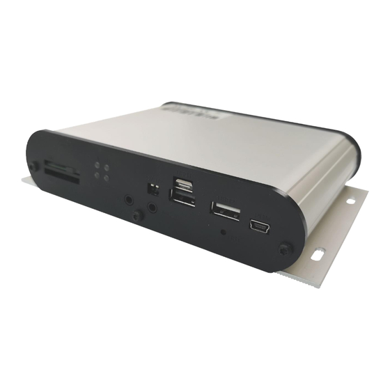
RTCU NX-200 Technical Manual V1.00 Advanced Automotive M2MI/IoT Gateway External connections Overview Connections to external equipment are made via the connectors that are located on the back and front sides of the product. The front panel is equipped with connectors commonly accessed by the user: SIM-Card, SD-Card, DIP-Switches, audio input and output, LEDs, dual USB host ports, and USB slave service port. -
Page 11: Signal Overview
RTCU NX-200 Technical Manual V1.00 Advanced Automotive M2MI/IoT Gateway Signal Overview X4: COM2 SGND CAN2-H X5: FLXIN SGND CAN2-L AGND AGND FLXIN3 FLXIN4 FLXIN1 FLXIN2 X2: COM1 1-WIRE LED 1-WIRE SGND SGND X3: I/O CAN1-L CAN1-H AIN2 AGND SGND AIN1... - Page 12 RTCU NX-200 Technical Manual V1.00 Advanced Automotive M2MI/IoT Gateway Connector X1: 4 pin PWR connector overview Name Description SUPP Power supply, positive (+) connection DI1/IGN Digital input 1 / Ignition input (Shared with X3) SUPP Power supply, positive (+) connection...
- Page 13 RTCU NX-200 Technical Manual V1.00 Advanced Automotive M2MI/IoT Gateway Connector X4: 6 pins COM2 connector overview Name Description Transmit Data from serial port 1, RS232 compatible CAN2-H CAN-bus channel 2 H-signal CAN2-L CAN-bus channel 2 L-signal Receive Data for serial port 1, RS232 compatible...
-
Page 14: Logic Io Aps Holmboes Allé
RTCU NX-200 Technical Manual V1.00 Advanced Automotive M2MI/IoT Gateway Accessories for cable assembly. Order-code Name RT-O-TYCO-H4 Tyco, Connector house 4 pins. Bag with 10 pcs TYCO p/n: 794617-4 RT-O-TYCO-H6 Tyco, Connector house 6 pins. Bag with 10 pcs TYCO p/n: 794617-6 RT-O-TYCO-H12 Tyco, Connector house 12 pins. -
Page 15: Power Supply
Advanced Automotive M2MI/IoT Gateway Power supply The RTCU NX-200 device must be supplied with 8..36 VDC from an external DC power source connected to the 4 pin power connector. Positive power is applied to the SUPP pin, and the ground is connected to the PGND pin. -
Page 16: Digital Outputs
The maximum switch-able inductance is 20mH and must not be exceeded. The digital outputs are supplied through the X1 power connector that also supplies the rest of the RTCU unit. As this power is also the RTCU NX-200 main power, a power-fail would also affect the digital outputs. -
Page 17: Digital Inputs / Ignition Input
RTCU NX-200 Technical Manual V1.00 Advanced Automotive M2MI/IoT Gateway Digital Inputs / Ignition Input The digital inputs are all low pass filtered and transient protected. To activate the inputs, connect a positive voltage between the input and the GND connector. -
Page 18: Analog Inputs
RTCU NX-200 Technical Manual V1.00 Advanced Automotive M2MI/IoT Gateway Analog Inputs The analog inputs are voltage inputs specified with an operating range of 0V to 10V DC. The conversion resolution is up to 12 bit (0..4095). Please consult the RTCU IDE documentation for further details. -
Page 19: Flex Inputs
RTCU NX-200 Technical Manual V1.00 Advanced Automotive M2MI/IoT Gateway Flex Inputs The flex inputs are multi-mode inputs that can be configured to operate as either analog or as digital inputs. The operating range is from 0V to 30V DC and is configurable as digital inputs with customized threshold values. -
Page 20: Denmark
RTCU NX-200 Technical Manual V1.00 Advanced Automotive M2MI/IoT Gateway Specification for each flex input: Min. Typ. Max. Unit Protected against transients and Resolution low-pass filtered Precision %FSR Precision is based on Cut-off frequency measurements @ 25 ˚C Input impedance kΩ... -
Page 21: Can Communication Port
RTCU NX-200 Technical Manual V1.00 Advanced Automotive M2MI/IoT Gateway CAN communication port The RTCU provides the physical layer for the CAN (Controller Area Network) serial communication interface in accordance with the ISO 11898 standard. The CAN bus is designed for high-speed (up to 1Mbit) robust communication in especially harsh environments like those found in the automotive industry. -
Page 22: Rs232 Port 1
The port is a general-purpose RS232 port with all control signals according to EIA-561 which defines RS232 on a modular connector. The signals are available on the RJ-45 connector located on the top side of the RTCU NX-200 device. Connector SER2: RJ-45 connector overview, fully RS232 compatible... -
Page 23: Rs485 Communication Ports (Eia/Tia-485-A Compatible)
If the RTCU NX-200 is used as an endpoint node, the software jumper for both RS485 ports separately can be activated through the user application in order to terminate the RS485 communication lines with 120Ω. -
Page 24: Dc-Out
Please refer to the RTCU IDE documentation for details on the usage of this interface. USB Host interface The RTCU NX-200 offers two high-speed USB host ports on the standard USB A connector for connection of various USB devices. The host port 1 connector includes locking latch that locks the USB cable connector in position. -
Page 25: Denmark
RTCU NX-200 Technical Manual V1.00 Advanced Automotive M2MI/IoT Gateway 3 pin SPK Out Name Description SPK_OUT_P Differential speaker positive (+) output Ring SPK_OUT_N Differential speaker negative (-) output Sleeve N.A. Not connected internally 3 pin MIC In Name Description MIC_BIAS... -
Page 26: 3D Movement Sensor
Advanced Automotive M2MI/IoT Gateway 3D movement sensor The RTCU NX-200 device contains a 3-axis accelerometer, 3-axis gyroscope, and 3-axis magnetometer in order to detect vibration and motion. This sophisticated range of movement sensors allows to detect movement and position change in 3 directions, X-Y-Z with a force as high as 16g in acceleration, 2000 dps in rotation and 50 gauss in magnetic field. -
Page 27: Led Indicators
RTCU NX-200 Technical Manual V1.00 Advanced Automotive M2MI/IoT Gateway LED Indicators Four bi-colored (red and green) LED indicator is present on the front of the device (see graphical overview). Two bi-colored LED’s (A and B) are available to the user, and the remaining two LED’s (S1 and S2) are signaling the status and possible errors of the RTCU device. -
Page 28: System Led S1 And S2
RTCU NX-200 Technical Manual V1.00 Advanced Automotive M2MI/IoT Gateway System LED S1 and S2 The RTCU is equipped with two system LED’s, which shows the status and possible errors of the RTCU device. The different patterns are listed in the table below. If the color of the system LED S1 is yellow, the device is actively communicating with the RTCU IDE (or another program, supporting the RTCU RACP protocol). -
Page 29: Switches
(and all other LEDs OFF) Switches DIP-switch The RTCU NX-200 device contains two dip-switches. The dip switches are located on the front side of the device for easy user access (see graphical overview). System switch (RST) The RTCU NX-200 device contains a combined reset/diagnostic switch. This switch is accessible from the front of the unit (see graphical overview). -
Page 30: Internal Li-Ion Battery
Do not expose the device to water, saltwater or allow the battery to get wet. • Avoid strong impacts and shocks. For more information regarding the environmental limitations, see “Specifications for RTCU NX- 200” below or consult the RTCU NX-200 datasheet. Logic IO ApS. Ph: (+45) 7625 0210 Holmboes Allé 14... -
Page 31: World-Wide Lte Cat. 4 Cellular Engine
UMTS release 7, max. 42Mbps down / 5.76Mbps upload, (Cat 6) • Digitized audio / DTMF capability. WLAN and Bluetooth The RTCU NX-200 device contains a combined WLAN (Wi-Fi) and Dual-mode Bluetooth radio that shares the same antenna interface. WLAN Technical Data •... -
Page 32: 99-Channels Multi-Gnss Receiver
RTCU NX-200 Technical Manual V1.00 Advanced Automotive M2MI/IoT Gateway 99-channels multi-GNSS receiver MediaTek MT3333 Single Chip Super Sensitivity General: 99 acquisition / 33 tracking / up to 210 PRN channels. Multi GNSS engine for GPS, GLONASS, GALILEO and QZSS Support DGPS, SBAS (WAAS, EGNOS, MSAS, GAGAN). -
Page 33: Internal / External Sim-Card Readers
Please refer to Appendix A for a SIM card installation guide. The RTCU NX-200 is prepared for eSIM internally, which shares the SIM-card signals with the external SIM-reader. Please contact Logic IO for this option. -
Page 34: Sd-Card Reader
SD-CARD reader The RTCU NX-200 device has a standard SD-CARD reader which is located on the bottom side of the device (see graphical overview) The RTCU NX-200 supports a FAT filesystem for standard PC- compatibility with up to 32 GB capacity support. -
Page 35: Product Identification Label With Barcode
The RTCU NX-200 product identification is found on the exterior of the device and contains a unique serial-number in readable form and as a barcode. The first three digits in the serial number identify the device type, and for the RTCU NX-200 device, this unique code is 321 or 322. -
Page 36: Denmark
RTCU NX-200 Technical Manual V1.00 Advanced Automotive M2MI/IoT Gateway The table below shows detailed information about the typical power consumption for the RTCU NX-200 device when it is in power-saving modes. The following power-saving modes are used: Mode 1: LED blinks every ~10 s, resumes the application when it is awoken. -
Page 37: Appendix A - Installing The External Sim-Card
RTCU NX-200 Technical Manual V1.00 Advanced Automotive M2MI/IoT Gateway Appendix A – Installing the external SIM-Card The external accessible SIM card reader has a push/push eject system and a mechanical lock for secure installation of the SIM card. Orientate the card as shown below and insert it into the card reader. Push the card into the reader until a click sound occurs –... -
Page 38: Appendix B - Installing The Internal Sim-Card
RTCU NX-200 Technical Manual V1.00 Advanced Automotive M2MI/IoT Gateway Appendix B – Installing the internal SIM-Card WARNING: Disassembling the device must be performed by a professional personal. ATTENTION: The device internal electronics are sensitive to Electrostatic Discharge (ESD) and must be handled only in an ESD safe environment. -
Page 39: Denmark
RTCU NX-200 Technical Manual V1.00 Advanced Automotive M2MI/IoT Gateway 4. The circuit board will not have to be completely removed from the housing. The SIM-card orientation on the reader is as follows: 5. Insert the SIM-card in the hinge Logic IO ApS. -
Page 40: Denmark
RTCU NX-200 Technical Manual V1.00 Advanced Automotive M2MI/IoT Gateway 6. Close and lock the card reader Lock Unlock 7. Push the circuit board into the encapsulation gently until the internal battery holder hits the battery compartment of the encapsulation. The circuit board can't be pushed further until the fixing flaps of the battery holder are squeezed inside the battery compartment of the encapsulation. -
Page 41: Appendix C - Installing The Sd-Card
Installing this jumper, and thereby enabling the CAN-bus Write capability of the unit, is done on the sole responsibility of the user. Logic IO can not be held responsible for any problems, or damage due to the decision to enable the CAN-bus Write capability. -
Page 42: Appendix E - Open Source Disclaimer
Be careful not to tighten the screws too much, thereby damaging the aluminum. Appendix E - Open Source Disclaimer The RTCU NX-200 products include several open-source software tools. This open-source software is governed by the terms and conditions of the applicable open source license, and you are bound by the terms and conditions of the applicable open source license in connection with your use and distribution of the open-source software in this product. -
Page 43: Rtcu Nx-200 Specifications
RTCU NX-200 Technical Manual V1.00 Advanced Automotive M2MI/IoT Gateway RTCU NX-200 Specifications Cellular Engine Bluetooth RTCU M2M Platform • • • LTE Cat.4 Engine(World Wide). Classic and Low Energy (LE). NX32L Execution Architecture. Max 150 Mbps(DL)/Max 50 Mbps(UL). • •... -
Page 44: Denmark
RTCU NX-200 Technical Manual V1.00 Advanced Automotive M2MI/IoT Gateway I/O Interface Physical Characteristics Power Management • • • 4 x digital solid-state digital output. Encapsulation: Aluminium profile. Low-power modes. Max. 36 volt / 1.5 A per. channel. • • Colour: Anodized natural grey. -
Page 45: Denmark
RTCU NX-200 Technical Manual V1.00 Advanced Automotive M2MI/IoT Gateway * * * * END OF DOCUMENT * * * * Logic IO ApS. Ph: (+45) 7625 0210 Holmboes Allé 14 Fax: (+45) 7625 0211 8700 Horsens Page 45 of 45 Email: support@logicio.com...
Need help?
Do you have a question about the RTCU NX-200 and is the answer not in the manual?
Questions and answers