Table of Contents
Advertisement
Advertisement
Table of Contents

Related Manuals for Logic IO RTCU MX2 turbo


Summary of Contents for Logic IO RTCU MX2 turbo
- Page 1 RTCU MX2 turbo Technical Manual Version 2.04...
-
Page 2: Introduction
RTCU MX2 turbo please refer to the RTCU IDE documentation. The RTCU MX2 turbo adds a new chapter to the highly successful era of the MX2 series, which were originally launched in 2006 as the first member in the X32 architecture generation of RTCU products. -
Page 3: The Technical Highlights Of The Rtcu Mx2 Turbo
RTCU MX2 turbo Technical Manual V2.04 The technical highlights of the RTCU MX2 turbo: ➢ Based on the RTCU M2M Platform ➢ NX32 execution architecture. ➢ RTCU IDE development tool with a full featured device simulator. o Huge standard API with more than 800+ functions. - Page 4 RTCU MX2 turbo Technical Manual V2.04 * * * * THIS PAGE IS INTENTIONALLY LEFT BLANK * * * Logic IO ApS. Ph: (+45) 7625 0210 Holmboes Allé 14 Fax: (+45) 7625 0211 8700 Horsens Page 4 of 36 Email: support@logicio.com Denmark www.logicio.com...
-
Page 5: Table Of Contents
RTCU MX2 turbo Technical Manual V2.04 Table of contents Introduction ..............................2 The technical highlights of the RTCU MX2 turbo: ..................3 Graphical view ..............................6 External connections ............................7 Overview ..............................7 Accessories for cable assembly ........................9 Power supply ............................. 10 Digital Outputs ............................ -
Page 6: Graphical View
RTCU MX2 turbo Technical Manual V2.04 Graphical view Logic IO ApS. Ph: (+45) 7625 0210 Holmboes Allé 14 Fax: (+45) 7625 0211 8700 Horsens Page 6 of 36 Email: support@logicio.com Denmark www.logicio.com... -
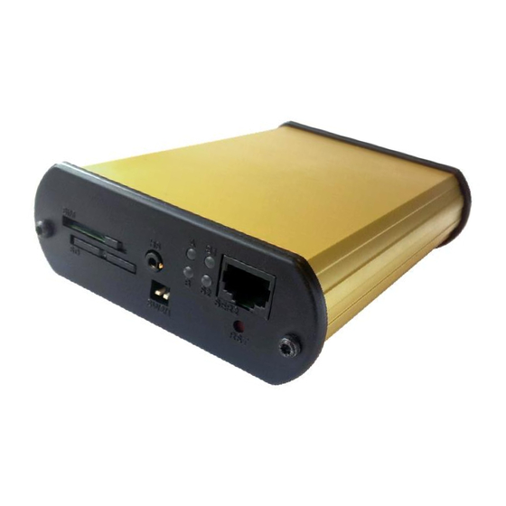
Page 7: External Connections
RTCU MX2 turbo Technical Manual V2.04 External connections Overview Connections to external equipment are done via the connectors located on the back and front of the RTCU MX2 turbo. The front panel is equipped with connectors commonly accessed by the user: SIM-Card, SD- CARD, DIP-Switch, Headset, LED’s and RS232. - Page 8 RTCU MX2 turbo Technical Manual V2.04 Connector X1: 4 pin PWR connector overview Name Description SUPP Power supply, positive (+) connection DI5/IGN Digital input 5 / Ignition input (Shared with X3) SUPP Power supply, positive (+) connection PGND Power Ground...
-
Page 9: Accessories For Cable Assembly
RTCU MX2 turbo Technical Manual V2.04 Connector X4: 6 pin SER1 connector overview Name Description Transmit Data from serial port 1, RS232 compatible RS-DET Programming cable detect, normally unconnected (if programming cable, connect to GND) DC-Out +3.3V/150mA DC-Out for external equipment. -
Page 10: Power Supply
RTCU MX2 turbo Technical Manual V2.04 Power supply The RTCU MX2 turbo device must be supplied with 8..36 VDC from an external DC power source connected to the X1 connector. Positive power is applied to the SUPP pin, and ground is connected to the PGND pin. -
Page 11: Digital Outputs
The maximum switchable inductance is 20mH and must not be exceeded. The digital outputs are supplied through the X1 power connector that also supplies the rest of the RTCU unit. As the power is also the RTCU MX2 turbo main power, a power-fail would also affect the digital outputs. -
Page 12: Digital Inputs / Ignition Input
RTCU MX2 turbo Technical Manual V2.04 Digital Inputs / Ignition Input The digital inputs are all low-pass filtered and transient protected. To activate the inputs, connect a positive voltage between the input and the GND connector. Please note: The DIN 5/IGN input is a special input as it also functions as the ignition input. If the ignition input is activated with a logical high or low (Wait For Event mode only), when the RTCU is in low power mode, it will wake-up the unit. -
Page 13: Analog Inputs
RTCU MX2 turbo Technical Manual V2.04 Analog Inputs There are two analog inputs available on the unit. The analog inputs are voltage inputs specified with an operating range of 0V to 10V DC. The conversion resolution is 12 bit +/- 1.5% FSR @ 25 degrees ˚C. -
Page 14: Rs232 Port 1 / Programming Port
RTCU MX2 turbo Technical Manual V2.04 RS232 port 1 / programming port This port can be used as general-purpose RS232 serial port or as a programming port. In order to use the port for programming, the RS-DET pin must be connected to GND. When using the port as general-purpose RS232, the RS-DET pin must be left unconnected. -
Page 15: Rs485
RTCU MX2 turbo Technical Manual V2.04 RS485 RS485 is available on the X2 connector as serial port 1. The RS485 bus a multi-drop network with a maximum of 32 units connected simultaneously to the bus. The RS485 bus contains an RS485+... -
Page 16: Can
RTCU MX2 turbo Technical Manual V2.04 The RTCU MX2 turbo provides the physical layer for the CAN (Controller Area Network) serial communication interface in accordance with the ISO 11898 standard. The CAN bus is designed for high-speed (up to 1Mbit) robust communication in especially harsh environments like those found in the automotive industry. -
Page 17: 1-Wire Bus
For 1-Wire ID-Button readers, which include a built-in LED, a dedicated output is available for this purpose. Please consult the RTCU IDE documentation for further information. For further information regarding modular 1-wire concept, please refer to the document “Modular 1-Wire Concept Technical Manual” on the Logic IO webpage. X2: 12 pin COM connector overview Name... -
Page 18: Hands-Free Connector
RTCU MX2 turbo Technical Manual V2.04 Hands-free connector The RTCU unit has a 4-pole 2.5mm jack connector for connecting a hands-free set to the built-in GSM modem. The speaker output is amplified through the internal Class-D amplifier and is a differential (balanced) signal. -
Page 19: 3D Movement Sensor
RTCU MX2 turbo Technical Manual V2.04 3D movement sensor The RTCU MX2 turbo unit contains a 3-axis accelerometer in order to detect both vibration and motion. It makes it possible to detect movement and position change in 3 directions, X-Y-Z with a force as high as 16g. -
Page 20: Led Indicators
RTCU MX2 turbo Technical Manual V2.04 LED Indicators Three bi-colored (red and green) and a single yellow LED indicator are present on the front of the unit (see graphical view). Two bi-colored LED’s (A and B) are available to the user and the remaining two LED’s (S1 and S2) are signaling the status and possible errors of the RTCU unit. -
Page 21: System Led S1 And S2
RTCU MX2 turbo Technical Manual V2.04 System LED S1 and S2 The RTCU is equipped with two system LED’s which shows the status and possible errors of the RTCU unit. The different patterns are listed in the table below. If the color of the system LED S1 is yellow, the unit is actively communicating with the RTCU IDE (or another program, supporting the RTCU RACP protocol). -
Page 22: Switches
RTCU MX2 turbo Technical Manual V2.04 Switches DIP-switch The RTCU MX2 turbo unit contains a dipswitch with two switches. The dipswitch is located on the front panel for easy user access (see the graphical view). System switch (RST) The RTCU MX2 turbo unit contains a combined reset/diagnostic switch. This switch is accessible from the front of the unit (see graphical view) It is necessary to use a small thin object with a diameter of approx. -
Page 23: Internal Li-Ion Battery
Do not expose the unit to water, salt water or allow the battery to get wet. • Avoid strong impacts and shocks. For more information regarding the environmental limitations see “Specifications for RTCU MX2 turbo” below or consult the RTCU MX2 turbo Datasheet. Logic IO ApS. Ph: (+45) 7625 0210 Holmboes Allé 14... -
Page 24: Internal / External Sim-Card Readers
RTCU MX2 turbo Technical Manual V2.04 Internal / External SIM-card readers The RTCU MX2 turbo unit contains both an internal and an external standard mini-SIM card reader. The external reader is located on the front panel (please see the graphical view) and is easily accessed. -
Page 25: Installing The Internal Sim-Card
Please refer to Appendix B for detailed description of installing the internal SIM-card. SD-CARD reader The RTCU MX2 turbo unit has a standard SD-CARD reader with a FAT32 file-system support for standard PC-compatibility, with up to 32 GB capacity support. -
Page 26: Installing The Sd-Card
RTCU MX2 turbo Technical Manual V2.04 The differences in write endurance between commercial grade MLC flash and ATP Industrial grade SLC flash is quite remarkable for write-intensive applications: Total Writeable Data Time Prediction Details Product Line Prediction @ 1GB @ 500 writes a day (1GB) -
Page 27: Antennas
The barcode found on the MX2 turbo unit contains the serial number. The first three digits in the serial-number identify the unit type. For the RTCU MX2 turbo this unique code is 292 or 286. For the RTCU MX2 turbo-2G the code is 293 or 285. -
Page 28: Power Consumption
RTCU MX2 turbo Technical Manual V2.04 Power consumption Detailed information on the maximum power consumption of the MX2 unit in different states and at different supply voltages is listed below. Maximum power consumption: Unit running on external supply Unit Active... -
Page 29: Specification For The 99-Channels Multi-Gnss Receiver
RTCU MX2 turbo Technical Manual V2.04 Specification for the 99-channels multi-GNSS receiver MediaTek MT3333 Single Chip Super Sensitivity General: 99 acquisition / 33 tracking / up to 210 PRN channels. Multi GNSS engine for GPS, GLONASS and QZSS Support DGPS, SBAS(WAAS,EGNOS,MSAS,GAGAN). -
Page 30: Specification For The Umts And Quad-Band Gsm Engine
RTCU MX2 turbo Technical Manual V2.04 Specification for the UMTS and Quad-band GSM engine The RTCU MX2 turbo is available in three versions: SKU version GSM frequency UMTS/HSDPA frequency Market MX2T 900/1800 MHz 900/2100 MHz EMEA/APAC 3G. MX2T-2G 850/900/1800/1900 MHz World-wide GSM. -
Page 31: Appendix A - Assembling/Disassembling Of The Unit
RTCU MX2 turbo Technical Manual V2.04 Appendix A – Assembling/disassembling of the unit The CAN write enable jumper and a SIM-card reader are located inside of the unit. In order to gain access to these interfaces, it is necessary to remove the internal board from the aluminum encapsulation. -
Page 32: Appendix B - Installing A Sim-Card Into The Internal Sim-Card Reader
RTCU MX2 turbo Technical Manual V2.04 Appendix B – Installing a SIM-card into the internal SIM-card reader To get access to the internal SIM-card reader it is necessary to disassembly the device as described in Appendix A. Internal SIM-card reader The SIM card reader is a lid-based type with a mechanical lock to secure a safe installation. - Page 33 RTCU MX2 turbo Technical Manual V2.04 SIM card orientation Lock Open SIM inserted and locked Logic IO ApS. Ph: (+45) 7625 0210 Holmboes Allé 14 Fax: (+45) 7625 0211 8700 Horsens Page 33 of 36 Email: support@logicio.com Denmark www.logicio.com...
-
Page 34: Appendix C - Enabling The Can Bus Write Capability
Installing jumper JP901, and thereby enabling the CAN-bus Write capability of the unit, is done on the sole responsibility of the user. Logic IO can not be held responsible for any problems, or damage due to the decision to enable the CAN-bus Write capability. - Page 35 RTCU MX2 turbo Technical Manual V2.04 3. Install the jumper as shown above 4. Mount the end-panel and secure it with the screws. Logic IO ApS. Ph: (+45) 7625 0210 Holmboes Allé 14 Fax: (+45) 7625 0211 8700 Horsens Page 35 of 36 Email: support@logicio.com...
-
Page 36: Rtcu Mx2 Turbo Specifications
RTCU MX2 turbo Technical Manual V2.04 RTCU MX2 turbo Specifications Processor and Main-memory Battery and Charger External Interfaces. • • Powerful 32-bit ST ARM7 processor. • On-board 2Ah (nominal) Li-Ion battery. SIM-card slot for micro-SIM with lock and • •...
Need help?
Do you have a question about the RTCU MX2 turbo and is the answer not in the manual?
Questions and answers