Table of Contents
Advertisement
Quick Links
Advertisement
Table of Contents

Related Manuals for Logic IO RTCU NX-910


Summary of Contents for Logic IO RTCU NX-910
- Page 1 RTCU NX-910 Advanced Industrial M2M/IoT Gateway Technical Manual Version 1.02...
-
Page 2: Introduction
NX32 applications can execute without changes. The RTCU NX-910 is designed to meet the ever-increasing challenges on security, in that it offers full TLS on all major protocols and includes a hardened protected execution environment with dual-boot and automatic fallback and recovery. - Page 3 RTCU NX-900 Technical Manual V1.02 Advanced M2M/IIoT Gateway * * * * THIS PAGE IS INTENTIONALLY LEFT BLANK * * * Logic IO ApS. Ph: (+45) 7625 0210 Holmboes Allé 14 Fax: (+45) 7625 0211 8700 Horsens Page 3 of 45 Email: support@logicio.com...
-
Page 4: Table Of Contents
Appendix B – Installing the SIM card ....................41 Appendix C – Installing the Micro SD card ..................42 Appendix D – Open Source Disclaimer ..................... 43 RTCU NX-910 Specifications ......................44 Logic IO ApS. Ph: (+45) 7625 0210 Holmboes Allé 14... - Page 5 RTCU NX-900 Technical Manual V1.02 Advanced M2M/IIoT Gateway Logic IO ApS. Ph: (+45) 7625 0210 Holmboes Allé 14 Fax: (+45) 7625 0211 8700 Horsens Page 5 of 45 Email: support@logicio.com Denmark www.logicio.com...
-
Page 6: Important Information
Logic IO Aps has failed to eliminate these errors or inaccuracies for this reason. - Page 7 ➢ Up to 4 digital inputs can be configured as IEC62053-31 Class A compliant. ➢ Expandable I/O with standard Modbus modules. Sensors: ➢ Temperature sensor. Logic IO ApS. Ph: (+45) 7625 0210 Holmboes Allé 14 Fax: (+45) 7625 0211 8700 Horsens Page 7 of 45 Email: support@logicio.com...
- Page 8 ➢ IP65 protected for outdoor usage. Regulatory Approvals: ➢ Radio Equipment Directive, RED 2014/53/EU. ➢ EMC Directive, 2014/30/EU. ➢ 2011/65/EU RoHS Directive. Logic IO ApS. Ph: (+45) 7625 0210 Holmboes Allé 14 Fax: (+45) 7625 0211 8700 Horsens Page 8 of 45 Email: support@logicio.com...
-
Page 9: Migration From Rtcu Ax9 Encore
RTCU NX-900 Technical Manual V1.02 Advanced M2M/IIoT Gateway Migration from RTCU AX9 encore: There are the following differences between the RTCU AX9 encore and the RTCU NX-910: Topic AX9 encore NX-910 Digital input – S0 Enabled by default Disabled by default... -
Page 10: Graphical Overview
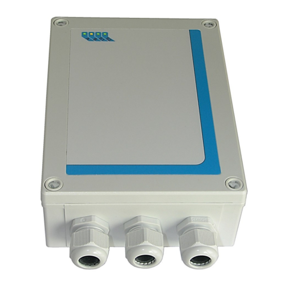
Advanced M2M/IIoT Gateway Graphical overview: There are four user controlled LEDs and four system LEDs for simple information and status on front of the RTCU NX-910: User LEDs System LEDs The external antenna connectors are located at the top-side of the device, as shown below: Logic IO ApS. -
Page 11: Connections
The placement of the terminals makes installation easy by using the cable glands and thereby maintaining the IP-65 protection. The RTCU NX-910 is delivered with three M20 cable glands. A graphical overview of the device is shown below:... - Page 12 SGND Signal ground. RS485_2+ RS485 non-inverting signal for RS485 port 2. RS485_2- RS485 inverting signal for RS485 port 2. Logic IO ApS. Ph: (+45) 7625 0210 Holmboes Allé 14 Fax: (+45) 7625 0211 8700 Horsens Page 12 of 45 Email: support@logicio.com Denmark www.logicio.com...
- Page 13 Connector Ethernet This is a standard 10Base-T/100Base-TX IEEE 802.3 compliant Ethernet connector. Please use an appropriate connector and cable, such as a standard CAT-5 twisted pair patch cable Logic IO ApS. Ph: (+45) 7625 0210 Holmboes Allé 14 Fax: (+45) 7625 0211...
-
Page 14: Power Supply
Dual Supply Note: The RTCU NX-910 can be supplied with both VAC and VDC at the same time. The device will run on the VAC supply if the VDC supply voltage is < +24VDC. If the VDC supply voltage is higher it will run on the VDC supply. -
Page 15: Dc Supply
Advanced M2M/IIoT Gateway DC Supply The RTCU NX-910 can be supplied with 8-36VDC from an external DC power source. Positive power is applied to the DCIN pin and ground is connected to the XGND pin. The DC supply of the NX-910 is protected against wrong polarity. If a system ground is connected to either SGND or AGND, a wrong polarity on the supply lines will destroy the internal GND connection. -
Page 16: Ac Supply
The RTCU NX-910 device can be supplied with 100-265VAC (50/60Hz) from a standard wall plug or any other high-voltage VAC power rail. The AC supply of the RTCU NX-910 is a highly efficient switch mode power supply and the AC input is protected internally with a 2A/250V Fast Acting non-replaceable fuse. - Page 17 Earth ground through a high impedance connection. For the best EMI performance/ESD immunity in combination with a common reference it is recommended to connect DC ground and Earth together with a low-inductance connection. Logic IO ApS. Ph: (+45) 7625 0210 Holmboes Allé 14...
-
Page 18: Digital I/O
The RTCU NX-910 device offers a very advanced power management which makes it possible to have one or more outputs enabled while the RTCU is in low-power mode. Please consult the RTCU IDE on-line help for more information. -
Page 19: Digital Inputs / S0 Inputs / Wakeup (Ignition) Input
S0 compliant inputs (IEC62053-31, Class A compatible) In S0 configuration the relevant RTCU NX-910 input will act as a ‘pulse input device’, and a current is supplied into the input connector so that a simple switch between SGND and the appropriate input will activate it. - Page 20 The DI5 / wakeup (ignition) input is a special input as it also functions as the ignition. If the input is activated with a logical high when the RTCU NX-910 is in power down mode, it will wake the device. A power apply will also wake the device up if it is in power-down mode.
-
Page 21: Analog I/O
Analog I/O Analog inputs The RTCU NX-910 device has two analog inputs which can be configured individually to work either as voltage or current measurement inputs by using the configuration jumper. The range in voltage mode is 0-10VDC and in current mode 0-20mA. - Page 22 Resolution Accuracy is based on measurements Accuracy %FSR @ 25 ˚C Cut-off frequency Input impedance Ω Logic IO ApS. Ph: (+45) 7625 0210 Holmboes Allé 14 Fax: (+45) 7625 0211 8700 Horsens Page 22 of 45 Email: support@logicio.com Denmark www.logicio.com...
-
Page 23: Usb Programming Port
A standard USB cable can be used between the device and the PC. RS232 communication ports (EIA/TIA-232 and V.28/V.24 compatible) Two general purpose RS232 ports available on the RTCU NX-910 device. Both are compliant with the EIA/TIA-232 standard. -
Page 24: Rs485 Communication Ports (Eia/Tia-485-A Compatible)
When the RTCU NX-910 device is used as endpoint device, the hardware jumpers TER1 and TER2 can be installed to terminate the RS485 communication lines with 120Ω. -
Page 25: Rs485 Port 1
RS485 inverting signal (B) SGND Signal ground This RS485 port must be addressed as port 3 when using the VPL API such as the serOpen function. Logic IO ApS. Ph: (+45) 7625 0210 Holmboes Allé 14 Fax: (+45) 7625 0211 8700 Horsens Page 25 of 45 Email: support@logicio.com... -
Page 26: 1-Wire
Total weight DC-Out Two DC outputs are available on the RTCU NX-910 for supplying external equipment; a 5V and a 12V/24V output. It is possible to control these DC outputs in order to save power. Both DC outputs are short circuit- (to ground), ESD- and transient-protected. -
Page 27: 12V/24V Dc-Out
Signal ground. Ethernet The RTCU NX-910 offers an on-board IEEE 802.3 compatible 100BASE-T Ethernet MAC controller and transceiver for communication with peripherals and back-end systems over standard Ethernet. Please refer to the RTCU IDE documentation for details on the usage of this interface. -
Page 28: Led Indicators
They are easily accessed from within the application program, and it is possible to mix the LED’s to obtain a third color: yellow. Please consult the RTCU IDE documentation for more information. Logic IO ApS. Ph: (+45) 7625 0210 Holmboes Allé 14... -
Page 29: System Led S1 And S2
On yellow (and all other LEDs The device is booting, initializing the system OFF) 13 Or yellow when communicating with the RTCU IDE or another program, supporting the RTCU RACP protocol). Logic IO ApS. Ph: (+45) 7625 0210 Holmboes Allé 14 Fax: (+45) 7625 0211... -
Page 30: Switches
(and all other LEDs OFF) Switches DIP-Switch The RTCU NX-910 device contains four dipswitches, where three of them are available for the application to use. The dipswitches are located inside the device (see drawing below or graphical view). System switch (RST) The RTCU NX-910 device contains a combined reset/diagnostic switch. -
Page 31: Internal Li-Ion Battery
Do not expose the device to water, saltwater or allow the battery to get wet. • Avoid strong impacts and shocks. For more information regarding the environmental limitations, see “RTCU NX-910 Specifications” below or consult the RTCU NX-910 datasheet. Logic IO ApS. -
Page 32: Lte Cat. 1 Cellular Engine
RTCU NX-900 Technical Manual V1.02 Advanced M2M/IIoT Gateway LTE Cat. 1 Cellular Engine The RTCU NX-910 uses an LTE/UMTS/HSPA engine with the following features: • Max. 10 Mbps down / 5 Mbps upload (Cat 1). • LTE-FDD: B1/B3/B7/B8/B20/B28A. • WCDMA: B1/B8. -
Page 33: Antennas
Antennas Cellular antenna The RTCU NX-910 device contains an SMA female connector for connecting a suitable antenna. When installing the antenna, please make sure that the antenna is not in close proximity to metallic parts or anything else that can influence the efficiency of the antenna. -
Page 34: Internal Sim-Card Reader
SIM-Card reader Micro SD-Card reader The RTCU NX-910 device has a standard Micro SD card reader which is located inside the device (see drawing below or graphical view). The Micro SD card reader is a lid-based system with a mechanical lock for reliable insertion and operation. -
Page 35: Approved Micro Sd Cards
For applications that use the SD-CARD media extensively and where a failure is critical, it is recommended to use approved Industrial Grade SD-CARDs. Logic IO has approved and recommends industrial grade SD-CARDs from ATP that is available in capacities from 512 MB to 32 GB. -
Page 36: Product Identification Label With Barcode
Advanced M2M/IIoT Gateway Product Identification Label with Barcode The RTCU NX-910 product identification is found on the exterior of the device and contains a unique serial-number in readable form and as a barcode. The first three digits in the serial-number identify the device type, and for the RTCU NX-910 device this unique code is 332. -
Page 37: Power Consumption
Device active while charging Note: Values marked with (*) is average and should be considered as guidelines as they may vary depending on the cellular signal strength. Logic IO ApS. Ph: (+45) 7625 0210 Holmboes Allé 14 Fax: (+45) 7625 0211... - Page 38 Note: The power consumption for wake on S0 will be drawn as long as S0 is enabled. AC power consumption: Device operating in power-saving modes The power consumption from external AC is less than 1 W in all the power saving modes. Logic IO ApS. Ph: (+45) 7625 0210 Holmboes Allé 14...
-
Page 39: Appendix A - Device Configuration Guide
Enables/disables on-board 120Ω line termination resistors which are according to standards; RS485 communication requires a proper line termination value (120Ω assuming a CAT5 twisted pair cable is used) resistors in both ends of the bus. If the RTCU NX-910 device is used as endpoint, the relevant jumper can be installed. - Page 40 These jumpers are used for connecting the DC OUT terminal to 12V or 24V. The following figure shows the location of the jumpers when the lid of the device is removed. Red lined boxes show the default state of the jumpers. Logic IO ApS. Ph: (+45) 7625 0210 Holmboes Allé 14...
-
Page 41: Appendix B - Installing The Sim Card
The SIM card can now be removed. SIM card orientation. Open Lock SIM inserted and locked Logic IO ApS. Ph: (+45) 7625 0210 Holmboes Allé 14 Fax: (+45) 7625 0211 8700 Horsens Page 41 of 45 Email: support@logicio.com... -
Page 42: Appendix C - Installing The Micro Sd Card
Avoid removing the Micro SD card during access to the card. Micro SD card orientation. Open Lock Micro SD card inserted and locked. Logic IO ApS. Ph: (+45) 7625 0210 Holmboes Allé 14 Fax: (+45) 7625 0211 8700 Horsens Page 42 of 45 Email: support@logicio.com... -
Page 43: Appendix D - Open Source Disclaimer
Advanced M2M/IIoT Gateway Appendix D – Open Source Disclaimer The RTCU NX-910 products include several open source software tools. This open source software is governed by the terms and conditions of the applicable open source license, and you are bound by the terms and conditions of the applicable open source license in connection with your use and distribution of the open source software in this product. -
Page 44: Rtcu Nx-910 Specifications
RTCU NX-900 Technical Manual V1.02 Advanced M2M/IIoT Gateway RTCU NX-910 Specifications Storage Wired Communication RTCU M2M Platform • • • Persistent data flash. 100BASE-T Ethernet interface. NX32 for Linux - NX32L. • • • Non-volatile SRAM. 2 x RS232. One with control signals. - Page 45 • On-board temperature sensor. (wihout external connectors. Technical data are subject to changes. * * * * END OF DOCUMENT * * * * Logic IO ApS. Ph: (+45) 7625 0210 Holmboes Allé 14 Fax: (+45) 7625 0211 8700 Horsens Page 45 of 45 Email: support@logicio.com...
Need help?
Do you have a question about the RTCU NX-910 and is the answer not in the manual?
Questions and answers