
Related Manuals for Faema E71 E


Summary of Contents for Faema E71 E
- Page 1 E71 E MANUALE DEL TECNICO ENGINEER'S MANUAL MANUEL DU TECHNICIEN TECHNIKERHANDBUCH MANUAL DEL TÉCNICO MANUAL DO TÉCNICO (rev. MT- E71E P0-1921)
- Page 3 LEGENDA LEGEND Interruttore generale Main switch Leva erogazione vapore Steam supply lever Boiler caffè Coffee boiler Display grafico Graphical display Piano appoggiatazze Cup warmer Pulsante acqua calda Hot-water button Tasto "STOP-CONTINUO" acqua calda Hot-water “STOP-CONTINUOUS” key Scorciatoia menu "Pressione caldaia" "Boiler pressure"...
- Page 4 LEYENDA LEGENDA Interruptor general Interruptor geral Palanca erogación vapor Alavanca de distribuição do vapor Calentador café Boiler café Display gráfico Display gráfico Calientatazas Grelha para aquecer chávenas Botón suministro agua caliente Botão de distribuição de água quente Tecla “STOP-CONTINUO” agua caliente Tecla “STOP-CONTÍNUO”...
- Page 5 E71 E tipo di macchina 2 gruppi 3 gruppi Type of machine 2 groups 3 groups type de machine 2 groupes 3 groupes Maschinentypen 2 Einheiten 3 Einheiten modelo de la máquina 2 grupos 3 grupos tipo de la màquina...
-
Page 6: Table Of Contents
Index Page Page BDS activation and sensor configuration Index Configuration MD3000 Bluetooth Description display symbols grinder/dispenser sensors Boiler shut off Setting recipes and connections with Coffee unit symbols Grinder/Dispenser Coffee dispensing Operating logic Quick access menu for the most frequently used Grinder control parameters configuration parameters on the machine Dose time variation relative to the Technical programming flow MD3000 Bluetooth Grinder/Dispenser Wi-Fi configuration Logo PROGRAMMING - TECHNICAL MODE Services logo... -
Page 7: Description Display Symbols
Description display symbols COLD MACHINE WATER LEVEL This symbol indicates the boiler water level. This symbol indicates that the machine is in its in- During the loading phase, the bottom part of the itial warming stage or that the boiler pressure has icon blinks. decreased to below 0.5 bar. When the optimum level is reached, the symbol It shows the boiler’s warming status and appears if one or more boilers are still in their initial warming looks like this: stage or if their temperature decreases to below 55°C. Pressing the “START/continue coffee” icon will cause dispensing to occur at the current tem- RESISTANCE perature. This symbol indicates that the resistance is All the other icons are disabled until required activated and functioning; a thicker luminous flow operating pressure is reached. - Page 8 Description display symbols Description display symbols PAYMENT SYSTEMS CONTROL OF THE FLOW (ONLY IF IN USE) The appearance of this animated icon means that This icon indicates that the machine is connected to a adjustments need to be made to the grinder/dispenser to payment systems interface and is configured to work with it. tighten or Dispensing is therefore possible subject to approval by the loosen the grinding, to return coffee dispensing to the payment system. default parameters. The icons that are shown are: - the red icon indicates that the cash system has denied the transaction; means that the grinding needs to be loosened. (flow of coffee is lower than the reference). - the blue icon indicates that the cash system has approved the transaction.
-
Page 9: Coffee Unit Symbols
Coffee unit symbols 5 keys 3 keys Boiler temperature indication. Pre-infusion phase, represented with the symbol and relative duration. Dispensing phase, represented with the symbol and relative duration. bar indicating the total progress of the operation. This icon appears when the coffee boiler is switched on and indicates when the set temperature has been reached. This icon indicates that the coffee boiler is heating up. 4 EN... -
Page 10: Coffee Dispensing
Coffee dispensing Press the coffee dispensing key The p re-infusion p hase s tarts, r epresented At the end of pre-infusion dispensing corresponding to the preferred dose. on the display for the group with the begins, represented by the symbol The LED corresponding to the selected symbol with the relative duration. and the relative duration. key will remain lit. T h e b a r b e l o w... -
Page 11: Quick Access Menu For The Most Frequently Used Parameters On The Machine
Quick access menu for the most frequently used parameters on the machine "Unit keys" shortcut menu NOTE. The group on the right is predefined. To set other groups press one of the relevant buttons "Boiler temperature" shortcut menu "Hot water button" shortcut menu "Boiler pressure"... - Page 12 Data flow chart - Technician programming Coffee Water C. Demand Demand Effectu Effectu Malfunc. 047.00.P0 --/--/-- - 3.7 050.00.P0 --/--/-- - 4.7 062.00.H0 --/--/-- V00. 49.18.19 Testing 7 EN...
-
Page 13: Programming Access
TECHNICIAN PROGRAMMING 1. Programming access Access the programming menu by pressing: 1) the key 2) the key 3) typing the password and pressing Return to the previous menu or exit the programming menu by pressing the key 8 EN... -
Page 14: Service Time Menu
2. Service time menu Access the service hours menu by These parameters can be configured: Press the icon USE - timed switch-on/switch-off: pressing the icon YES, NO, Eco (during the switch-off phase, the machine resistance is not completely disabled and allows the AUTOMATIC SWITCH OFF / SWITCH boiler pressure to remain at 0.2 bar). The machine can be set to switch off and ON - (switch-on time); OFF - (switch-off time); switch on at programmed times. Note. When the machine is working in CLOSED - (day of closure). -
Page 15: Language Selection
3. Language selection Press the icon to choose the desired Press the icon language. 4. INFO menu Malflunc. Counters Counters Sel. Setup Water C. Version Serial N. Coffee In the INFO menu, you can view: Press the icon Counters In the Counters menu the listed parameters are: Coffee Group... - (number of coffee-based beverages); Water - (number of times that water was dispensed); Steam - (disabled); Steam + Air - (disabled); Hot milk - (disabled); Cold milk - (disabled); Total Coffee - (total number of coffee-based beverages); Scroll through the entries using the - (time since last start up). and arrows. -
Page 16: Refill History
Refill History Water C. Demand Effectu 1) The items are scrolled by pressing the icons Press the icon to display the water refill history. 2) Press the key to clear/reset. Coffee history Coffee Demand Effectu 1) The items are scrolled by pressing the icons Press the icon to display the coffee wash archive. 2) Press the key to clear/reset. Fault history Malfunc. 1) The items are scrolled by pressing the icons Press the icon to display the malfunct. archive. -
Page 17: Version
Version The submenus of the "Version" item display the stored versions for 047.00.P0 --/--/-- - 3.7 example: - Master 047.00.P0; 050.00.P0 --/--/-- - 4.7 - Slave 050.00.P0; 062.00.H0 --/--/-- - Display 062.00.H0; - Firmware V00.49.18.19; V00. 49.18.19 - Bluetooth; - WIFI; - Group 076.00.B0. Scroll through the entries using the Press the icon to display the and arrows. -
Page 18: Programming Measures Function
5. Programming measures function COFFEE Press one of the coffee keys (ex. The icons of the programmable keys Press the icon Group 3). are shown on the services display. key can also be programmed as DOSED: NOTE. THE press the icon on the parameter display screen: When one of the coffee keys is pressed (e.g. the key), the following parameters are displayed on the services display: Press the icon to return to CONTINUOUS mode. Water dose; pre-infusion time; saturation time. The other functions of the key will remain unchanged The key in question will remain highlighted on the unit in both configurations. - Page 19 WATER Press the water key. These parameters can be configured: Press the icon SET... - to set the dispensing time; % - to set the water temperature. NOTE. - the red corner in the top left of the icon shows that the key is being modified. - the TEST phase of the water keys is exactly the same as that for the coffee keys Press the icon to confirm the information entered. Water dose programming using the "self-learning" function Place a container suitable for the The sound of the buzzer and the red Press key to be programmed. When amount you wish to fill beneath the hot- the desired level is reached in the corner in the top left of the container press the key again.
-
Page 20: Clone" Function
Clone function This feature allows you to replicate the coffee unit settings for all other machine groups. Press the icon Grup (ex. Press the icon Press the icon to confirm. Group 3). At the end of the process, all the groups will have the same parameters. 15 EN... -
Page 21: Hot Water Dispensing
Steam dispensing The steam lever offers some special features that make it extremely useful. "Purge" function One of the most interesting features is the "Purge" function, which makes it possible to eliminate any condensation that may have formed when a medium/long period of time passes between steam dispensing. To activate the "Purge" function, push the steam lever upwards and keep it in this position for several seconds. When the lever is released, it automatically returns to the starting position. "Purge" Modularity Another valuable function offered by the steam lever is modular dispensing. When the steam lever is pushed towards the cup tray, there are 2 different positions for the lever, offering two different levels of steam intensity:... -
Page 22: Testing
6. Testing The test screen permits manual operation Testing of the components in the machine. Press the icon Volumetric meter incremental counter Testing instant boiler temperature boiler activation percentage level signal; water level in boiler tested part boiler pressure Boiler load solenoid valve boiler resistance Boiler activation percentage: Modulation percentage of the heating power of the boiler. Boiler resistance: Activation of resistance elements on the basis of the power selected. Total power divided into: RC1 = ⅔ - RC2 = ⅓ Full power cycle: RC1 ON / RC2 ON Low power cycle: RC1 ON / RC2 OFF RC1 OFF / RC2 OFF RC1 OFF / RC2 OFF The selection of the parts to be moved is done by pressing the icons... -
Page 23: Washes
7. Washes Select from the following wash settings: - Coffee - Time Press the icon Coffee Wash: press the key • Choose the type of wash-cycle to perform • Confirm by pressing the icon • Follow the instructions on the display. This menu makes it possible to set the times requests appear for the water Time: press the key change in the boiler and the coffee circuit wash. - Page 24 Change: press the key Select which type of coffee wash you Change the time depending on your requirements and confirm with the The time appears under the key. want to perform. For example key. NOTES. It is possible to deactivate the scheduled washing request by pushing the key ; in this case no time appears under the key 19 EN...
-
Page 25: Cup Warmer
9. Cup Warmer Additional changes are possible using Select the heating level. Press the icon the "+" and "-" keys. 10. Heating element Service personnel can switch on or switch off the electric heating (service boiler and groups boilers) in this way: Returning to the main menu using the key the icon of the deactivated Press the icon heating element is displayed : all the heating elements and the self-leveller function of the service-boiler are deactivated. Icon in programming = enabled resistances (icon main menu); Icon in programming = disabled resistances (icon main menu). 20 EN... -
Page 26: Programming
11. Programming Press the icons to scroll through the entries. Press the icon Configuration of the parameter occurs by pressing the square of the parameter: press the desired icon on the screen and confirm with W e i g h t i n g s y s t e m - a l l o w s Control Time - display dispensing time: Grinder Control-1 YES/NO (from 1" to 60'). Grinder Control-2 management of the Acaia scales The parameters that can be set are: for weighing the amount of coffee Unit of Temperature - can be set to:... - Page 27 11. Programming Screensaver - Possibility of program- BDS - see section “BDS Activation” in Coffee Boiler - this parameter includes ming the screensaver display time the entries for setting the temperature the following pages. (from 30" to 20') of the coffee boilers, values that can Flush - Not active. be set are 60 to 110°C (140 to 230°F) Standard data - allows loading of in steps of 0.5°C. In this menu there is Low power - YES/NO standard data or reconfiguration of the also the possibility of programming an machine. In both cases the machine is Drying - Not active. offset of temperature for the boilers automatically restarted. which can be modified in a range of Password- allows change of the code +/- 2°C.
-
Page 28: Coffee Boiler
Bluetooth Connection Coffee Boiler The items are scrolled by pressing the icons Press the icon Press the icon Set the desired values using the "+" and "-" icons. NOTE: a temperature offset can be set for the boiler adjustable by ±2°C. E a c h d o t c o r r e s p o n d s t o approximately half a degree centigrade of offset. - Page 29 Procedure for Bluetooth connection with the machine-grinder unit ..Turn the machine on; the initial menu appears on the display. The icon indicates that the machine can be linked to a Bluetooth device. Press the icon To enter TECHNICAL programming, press the icon Press the icon Type the password and then press 1) The items are scrolled by pressing the icons Press the icon 2) Press the icon Find 1) The items are scrolled by pressing the icons The machine will find all Bluetooth devices within a range 2) Press the icon to confirm the selected device, an asterisk will appear next to the line of the grinder/ of 10 metres. dispenser to indicate the successful Bluetooth association with the machine: 24 EN...
- Page 30 MM-MOD TOUCH The blue icon indicates that the machine and the Exit from programming by pressing the icon grinder/dispenser are communicating. In the event of communication problems, the "COMMUNICATION FAILURE" message will appear on the display followed by the name of the disconnected grinder/dispenser. The message disappears automatically when the Bluetooth connection is restored. A common cause of this failure is the grinder/dispenser being turned off with the machine turned on. 25 EN...
-
Page 31: Bds Activation And Sensor Configuration
BDS activation and sensor configuration 1) The items are scrolled by pressing the icons Press the icon 2) Press the icon Note: With BDS active the payment systems cannot be activated. Press the icon to confirm. All the TECHNICAL MENU items of the "MD3000 Bluetooth" grinder/dispenser can be viewed only after the default technical code has been entered. SINGLE DOSE DOUBLE DOSE (Red) -
Page 32: Configuration Md3000 Bluetooth Grinder/Dispenser Sensors
CONFIGURATION MD3000 BLUETOOTH GRINDER/DISPENSER SENSORS 0: sensor disabled 1: single dose (Red) 2: double dose (Green) SINGLE DOSE (Red) B D S 1 - - 2 DOUBLE DOSE (Green) SPECIAL DOSE B D S (Blue) 1 - - 2 Single dose – Left sensor (Red) Double dose – Right sensor (Green) B D S 2 - - 1 B D S Double dose – Left sensor (Green) 0 - - 2 Single dose – Right sensor (Red) -
Page 33: Grinder/Dispenser
Setting recipes and connections with grinder/dispenser -NOTE: POSSIBILITY TO CONNECT ALSO WITH GRINDER/DISPENSER 2 GRINDER/DISPENSER 1 The filter holder-key and machine association logic is the following: 1-A or 2-A = activation of the first actuator (filter-holder with single delivery spout) 1-B o 2-B = activation of the second actuator (filter-holder with double delivery spout) 1-C or 2-C = activation of the third actuator with filter-holder with dedicated filter With the number 1 the first grinder/dispenser MM1 is identified With the number 2 the second grinder/dispenser MM2 is identified With the letters A-B-C-D-E the filter-holders are identified MEDIUM SHORT LONG Every button on the machine can be configured based on the type and the relative grinder/dispenser. Not all types can be used with the BDS system. The possible choices are: - Single type Short Medium -> SINGLE DOSE (Red) SINGLE DOSE DOUBLE DOSE Long -> SPECIAL DOSE (Blue) (Red) -
Page 34: Operating Logic
Operating logic BDS system enabled. Dispensing disabled NOTE: Start/Stop key is always active. 3 keys 5 keys Dose grinding and dispensing activated (key on) Dispensing will remain active for 2 minutes. During this time, the grinder/dispenser used will be blocked and therefore unable to grind a second dose of coffee. The grinder/dispenser will automatically release when the enabled key is pressed or when the two minutes of waiting time have elapsed. B L O C K E D 29 EN... -
Page 35: Grinder Control Parameters Configuration
Grinder control parameters configuration Grinder Control-1 Grinder Control-2 The parameters that can be set are: : not in use. Note: If the grinder control system is not in use, extraction time and calculated flow rate data will not be available or sent to the telemetry platform. 1) The items are scrolled by pressing the icons 2) Press the icon : manual grinder control (for grinder/dispensers with no bluetooth connection option. : automatic grinder control (bluetooth connection with grinder/dispenser). Note: For proper operation of the grinder control system, keys of the same type (for example singular ones relative to grinder/dispenser 1) must be programmed with the same saturation and pre-infusion parameters. Press the icon : manual grinder control (for grinder/dispensers with : not in use no bluetooth connection option). The parameters can be modified manually using the keys After completing operations confirm the values by pressing the key or exit and leave the previous data using the key : automatic grinder control (bluetooth connection with grinder/dispenser). 30 EN... - Page 36 Grinder control parameters configuration : manual grinder control (for grinder/dispensers with no bluetooth connection option. The appearance of this animated icon means that adjustments need to be made to the grinder/dispenser to tighten or loosen the grinding, to return coffee dispensing to the default parameters. The icons that are shown are: 1. disable grinder control, if in use. 2. set and calibrate the machine and grinder/dispenser as means that the grinding needs to be loosened. desired. (flow of coffee is lower than the reference). 3. dispense into the test square all the types of beverages to be used (double coffee, single coffee and any special blend - third key). means that the grinding needs to be tightened. 4. write down the satisfactory flow values of the coffees for (flow of coffee is greater than the reference). each of the possible three types of beverage. 5. go to the grinder control panel and perform reset. Note. The number next to the icon (1 or 2) indicates 6. set the flow values for each of the beverages. which grinder/dispenser needs adjusting. 7. enable grinder control. The icon appears on the display instead of the level sym- bol. Note: Set the Q.ref of double coffees first for proper func- tioning of grinder control. 31 EN...
- Page 37 Grinder control parameters configuration : Method 1: manual setting of Qref. 1. disable grinder control, if in use. 2. connect the machine to the grinder/dispenser via blue- tooth and enable dialogue in the manner already in use. 3. set and calibrate the machine and grinder/dispenser as desired. 4. dispense into the test square all the types of beverages to be used (double coffee, single coffee and any special blend - third magnum key on demand). 5. write down the satisfactory flow values of the coffees for each of the possible three types of beverage. 6. go to the grinder control panel and perform reset. 7. set the flow values for each of the beverages. 8. enable grinder control. : Method 2: setting of Qref in fully self-learning mode. Repeat the entire procedure for the second grinder/dis- penser if present. The machine is ready to work with the grinder control on. In the event of problems, dispensing can be performed in the test square with the grinder control in use to see if the symbol * is present beside the flow. Remember that dispensing is deemed valid only if it lasts more than 10 seconds. Other symbols are used in the test square: 1. Disable grinder control, if in use. 2. Connect the machine to the grinder/dispenser via blue- > if the flow is too high compared to the reference, above tooth and enable dialogue in the manner already in use. the upper limit 3. Programme and calibrate the machine and grinder/ < if the flow is too low compared to the reference, below dispenser as desired, dispensing the beverages until a the lower limit satisfactory cup result is achieved. 4. Go to the grinder control panel and perform reset.
- Page 38 Grinder control parameters configuration grinder control. Example of information on the flows of each single Press the icon dispensing sent to the Plat-One platform via WIFI. (A) GR1 single coffee, (B) GR 3 double coffee, (A/B) GR 2 central with one single coffee and one double, (C) the filter holder is not used for special coffees. Dose time variation relative to the MD3000 grinder/dispenser To increase or decrease the measure-time operate as follows: The measure-number correspondence is the following: DOSE 1 for the single measure 1) press the icon from the main screen: for the double measure DOSE 2 for the continuous measure * DOSE 3 Note: single-measure’s and continuous measure grinding time variation in user mode is ± 25 hundredths of second (0 ÷...
-
Page 39: Wi-Fi Configuration
WiFi configuration 1) The items are scrolled by pressing the icons Scroll through the items using the icons 2) Press the icon To deactivate the function press RESET. Reset the parameters with the icon - initialization of the standard data: Wi-Fi Menu - Configure the following Wi-Fi parameters as shown below: - NETWORK - enter the name of the access point. - SECURITY - indicate the type of wireless network security: - KEY - enter the password to access a protected Wi-Fi network (WPA or WEP) - URL - enter listener.gruppocimbali.com. - Port - enter 10000. - CONNECT - to connect to the access point selected. - RSSI - signal intensity: - IP - displays the IP address assigned to the machine by the wireless access point. -
Page 40: Logo
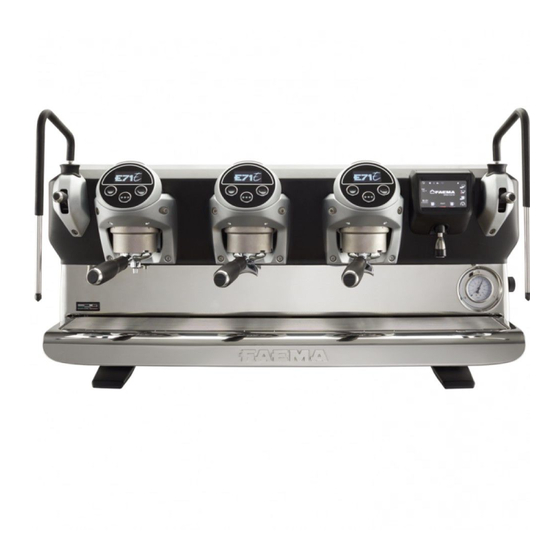
Logo The Faema standard logos are shown on all the machine displays, after a period of inactivity set for the "Screensaver" menu by the technician. The machine is supplied with the logo shown in the image. The user can replace it with another of the same size that will will appear on all displays (groups and services), creating the file custlogo.bmp (maximum size 260 x 110 pixels). To create a customised logo, proceed as follows: Using any graphics program (e.g. Paint), Insert the USB pen drive in the the icon will appear on the create a file that meets certain characteristics; dedicated slot on the machine: services display: the prerequisites for a bitmap image to be used as a custom logo are: custlogo.bmp • width less than or equal to 260 pixels; • length less than or equal to 110 pixels. • 24-bit bmp colour. Copy into a USB pen drive the file "custlogo.bmp" if the user wants to display the on the services display. -
Page 41: Services Logo
Services logo Return to the programming menu Press the icon Press the icon and press the icon Services display logo. Press the icon to confirm. Time Possibility of programming the screensaver display time (from 30" to 20') with steps of 30 seconds. Return to the programming menu Press the icon to confirm. and press the icon Press the icon 36 EN... - Page 42 Update from USB pen drive PRELIMINARY OPERATIONS Format a USB Pen Drive using the FAT32 format. If using Windows, use the predefined formatting settings as shown in the image. E71.ppf Copy the update files (CPU ; only for E71: DISPLAY ) to the main file path of tft_fw.ppf a USB Pen Drive. NOTE: do not turn off the machine or remove the USB Pen Drive until the update has been completed. If using a USB Pen Drive operating LED, this is shown by the LED flashing. PRELIMINARY OPERATION: Recognizing of USB support With the machine running, insert the USB Pen Drive containing the update files into the USB port. The icon will appear on the display to indicate that the storage device has been recognised. STARTING THE SOFTWARE UPDATE Turn the machine off leaving the USB Pen Drive inserted. With the subsequent restart, the upgrade of the two microprocessors (master and slave) begins with the file BOOT 3.6 UPDATING 015% The correct recognition of each file by the machine is signalled by a buzzer (200ms ON).
-
Page 43: Lights
When the status indicator reaches 100% the update In the next step, the display update begins. The screen is complete and the machine restarts automatically. shown is displayed on all of the machine’s touch screens. The following message appears when restarting: UPDATE SOFTWARE UPDATE COMPLETED REMOVE USB Remove the USB Pen Drive. Enter the standard information, update the machine data and reactivate the resistance. DISPLAY CALIBRATION The calibration procedure can be performed at any time by starting the machine with Dip 3 ON. The following message appears on all the displays when turned on: Using a pen hold down the centre of the cross; repeat the operation in all the points where the cross appears. Perform the calibration on all the displays or only on those where it is required. At the end of the operation, turn off the machine and return the Dip 3 to OFF. Lights This menu allows adjustment of the machine lights. Specifically: - rear panel - groups light... - Page 44 Updating the coffee unit keyboard from a USB drive PRELIMINARY OPERATIONS Format a USB drive using the FAT32 format. If using Windows, use the predefined formatting settings as shown in the image. Copy the update files ( E71EGApp.hex) onto the USB drive’s main path. NOTE:Do not turn off the machine or remove the USB Drive until the update has been completed. If using a USB drive with an operating LED, it will flash when the update is complete. With the machine on, insert the USB drive containing When the following message appears, support files the software update to be uploaded onto the machine. have been identified: UPDATE AVAILABLE Switch off the machine and remove the USB Drive. Turn the machine on again: The next step starts the update process. INSERT USB TO UPDATE DISPLAY With the machine on, insert the USB drive containing the update files into the USB port. When the update is complete, the display automatically restarts, and the following screen appears: Do not turn the machine off during the update!
-
Page 45: Recovery
Recovery PRELIMINARY OPERATIONS Format a USB Pen Drive using the FAT32 format. If using Windows, use the predefined formatting settings as shown in the image. Copy the recovery files ( ; only for E71: ) in the main path of the USB Pen E71_Recovery E71SOS.ppf Drive. START-UP WITH RECOVERY FILES Switch off the machine and insert the USB Pen Drive. Turn the machine on again: when it restarts, recovery will begin. The start of the procedure is indicated through an intermittent beep. During the update, the machine will beep at regular intervals. When the update is complete, the services display The following message is displayed on the machine's automatically restarts and the following message touch screen. appears: UPDATE COMPLETED REMOVE USB Remove the USB Pen Drive. Enter the standard data, update the machine data and reactivate the heating element, if necessary. 40 EN... -
Page 46: Touch-Display Test
Touch-display test The display-test procedure can be performed at any time by starting the machine with Dip 5 ON. Ensure that the information on the display is green, with no pressure on the screen. Service display. if the information is red, check for any undesired pressure on the edge of the screen. Service display. At the end of the operation, turn off the machine and return the Dip 5 to OFF. 41 EN... -
Page 47: Diagnostics Messages
12. Diagnostic messages MALFUN. CODE DESCRIPTION POSSIBLE CAUSES VERIFICATIONS and SOLUTIONS • USB-port current- USB power-supply • Check the status of the USB port and its malfunction. consumption too high. connections in order to identify possible causes of excessive consumption (e.g. short-circuit). • Once the cause of the malfunction is fixed the USB port should restore itself automatically and return to normal operation. • If the problem persists, replace the CPU board. • Sensor failure Group boiler pressure sensor • C heck cabling (x)21* • Card failure. x out of range (x = 1, 2, 3, 4) • R eplace the sensor Note: Group 1 is to the far left. - Page 48 MALFUN. DESCRIPTION POSSIBLE CAUSES VERIFICATIONS and SOLUTIONS CODE Group x boiler heating • C heck if the safety thermostat of the group x boiler (x)52* • T he group x boiler safety timeout - 20 minutes has been triggered, and reset it if necessary thermostat has been (x = 1, 2, 3, 4) • C heck if there are interruptions or detached triggered Note: Group 1 is to the far left. fastons on the cabling • The resistance is • C heck that the group x boiler resistance is not...
- Page 49 MALFUN. DESCRIPTION POSSIBLE CAUSES VERIFICATIONS and SOLUTIONS CODE Error in the group that is • C heck water is supplied from the main line. dispensing. • C heck there are no fitting obstructions or leakage. (x)66 (x = 1, 2, 3, 4) • C heck flowmeter electrical connections. Note: Group 1 is to the far left. • R eplace the broken flowmeter. • R eplace the broken board. Measure-grinder adjustment: Event only archived and not displayed on the Bluetooth set up by the display during normal machine operation.
- Page 50 MALFUN. DESCRIPTION POSSIBLE CAUSES VERIFICATIONS and SOLUTIONS CODE • Action desired by the Reset standard password. 097* user by entering the special code (applicable only for machines with TFT display). • Event only archived and not displayed on the • Initialisation malfunction Historical malfunctions and display during normal machine operation.
- Page 51 DISASSEMBLY AND SETTING ALL OPERATIONS MUST BE PERFORMED WITH THE MACHINE OFF AND COLD. TUTTE LE OPERAZIONI DEVONO ESSERE EFFETTUATE A MACCHINA SPENTA. TO ALWAYS USE THE NECESSARY SAFETY EQUIPMENT (SHOES/GLOVES). 13. Removal of the side panels 46 EN...
-
Page 52: Cup Warmer
14. Cup Warmer 47 EN... - Page 53 15. Stainless steel front panel 48 EN...
-
Page 54: Rear Panel
16. Rear panel The back panel may be removed only after the cup warmer has been removed. 49 EN... - Page 55 17. Draining the boiler water 50 EN...
-
Page 56: Removing The Boiler Heating Element
18. Removing the boiler heating element Remove the resistance only after emptying the boiler. 51 EN... -
Page 57: Coffee Boiler
20. Coffee boiler 0,6 mm 52 EN... -
Page 58: Display Panel
21. display panel 53 EN... -
Page 59: Junction Box
22. Junction Box 23. Safety thermostat 54 EN... -
Page 60: Peristaltic Pump
24. Peristaltic pump 25. CPU dip-switch CPU DIP-SWITCH CAUTION! When changing the position of the Dip-Switch, the machine MUST BE SWITCHED OFF. Under standard conditions, the dip-switches are positioned on OFF. The dip-switches have the following functions: - DIP 1 = OFF - DIP 2 = OFF - DIP 3 = OFF - ON calibration of the touch displays - DIP 4 = OFF - DIP 5 = OFF - ON touchscreen test - DIP 6 = ON - DIP 7 = OFF - DIP 8 = ON (*) Upon completion of the standard data input operations, position DIP 1 to OFF again. -
Page 61: Battery - Fuse
Battery - Fuse BATTERY CR 2032 CR 2032 FUSE 56 EN... - Page 62 1 2 3 4 5 6 1 2 3 4 1 2 3 4 1 2 3 4 5 6 57 EN...
- Page 63 1 2 3 4 5 6 1 2 3 4 1 2 3 4 1 2 3 4 5 6 58 EN...
- Page 64 EVTS P_EG3 EMAV P_EG2 P_EAR1 EAR1 P_EAC P_EMAV P_EVC 5V DV1 GND DV1 P_EG1 59 EN...
- Page 65 60 EN...
-
Page 66: Wiring Diagram
WIRING DIAGRAM LEGEND AL = Power supply Bo... = Boiler DV.. = Flowmeter Fi = Filter F UL = Fuse IG = Master switch Mo = Clamp MP.. = Pump motor RC = Service-boiler heating element Rsc = Cup warmer heating element St = Triac board TC = Service-boiler safety thermostat TB... = Coffee boiler safety thermostat = Remote-control switch TR = Transformer Connector list J1 = Keyboards... - Page 67 62 EN...
-
Page 68: Hydraulic Diagram
HYDRAULIC DIAGRAM LEGEND LEGEND LÉGENDE LEGENDA Bo = Chauffe-eau Bo = Boiler Bo = Coffee boiler Ca = Chaudière Ca = Caldaia Ca = Boiler DV = Doseur volumétrique DV = Dosatore volumetrico DV = Volumetric dispensing device Eac = Electrovanne eau chaude Eac = Elettrovalvola acqua calda Eac = Hot water solenoid valve Eaf = Electrovanne eau froide Eaf = Elettrovalvola acqua fredda Eaf = Cold water solenoid valve Ein = Electrovanne pré-infusion Ein = Elettrovalvola pre-infusione... - Page 69 Il Costruttore si riserva il diritto di modificare senza preavviso le caratteristiche delle apparecchiature presentate in questa pubblicazione The Manufacturer reserves the right to modify the appliances presented in this publication without notice Le fabricant se réserve le droit de modifier sans préavis les caractéristiques des appareils présentés dans cette publication Der Hersteller behält sich das Recht vor, die in dieser Veröffentlichung vorgestellten Geräte ohne Vorankündigung zu ändern...
Need help?
Do you have a question about the E71 E and is the answer not in the manual?
Questions and answers