Table of Contents
Advertisement
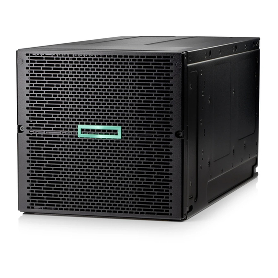
HPE Edgeline EL8000 Converged Edge System
Setup and Configuration Guide
Abstract
This document is for the person who installs, administers, and troubleshoots servers and storage systems.
Hewlett Packard Enterprise assumes you are qualified in the servicing of computer equipment and trained in
recognizing hazards in products with hazardous energy levels.
Part Number: P12853-003
Published: October 2019
Edition: 1
Advertisement
Table of Contents

Related Manuals for HPE Edgeline EL8000


Summary of Contents for HPE Edgeline EL8000
- Page 1 HPE Edgeline EL8000 Converged Edge System Setup and Configuration Guide Abstract This document is for the person who installs, administers, and troubleshoots servers and storage systems. Hewlett Packard Enterprise assumes you are qualified in the servicing of computer equipment and trained in recognizing hazards in products with hazardous energy levels.
- Page 2 Notices The information contained herein is subject to change without notice. The only warranties for Hewlett Packard Enterprise products and services are set forth in the express warranty statements accompanying such products and services. Nothing herein should be construed as constituting an additional warranty. Hewlett Packard Enterprise shall not be liable for technical or editorial errors or omissions contained herein.
-
Page 3: Table Of Contents
Installing the server blade into the chassis................................22 Configuration.........................24 Prepare for configuration........................................24 Connecting to Edgeline EL8000 Chassis Manager the first time....................... 24 Connecting to the web interface using Ethernet..........................24 Connecting to the CLI in a serial session..............................25 Edgeline EL8000 Chassis Manager web interface.............................. 25 Enabling JavaScript for Internet Explorer...............................26... - Page 4 The CM configured with static IP address reverts to DHCP when moved to a new chassis....38 Power problems........................................39 HPE Edgeline 1500 CM module powers on without being fully inserted to the chassis......39 Warranty and regulatory information................40 Warranty information..........................................40 Regulatory information........................................40...
- Page 5 -48VDC Hot Plug Power Supply...................................46 Websites..........................48 Support and other resources....................49 Accessing Hewlett Packard Enterprise Support..............................49 Accessing updates..........................................49 Customer self repair..........................................50 Remote support............................................50 Warranty information..........................................50 Regulatory information........................................50 Documentation feedback........................................51 Acronyms and abbreviations....................52...
-
Page 6: Overview
Overview The HPE Edgeline EL8000 Converged Edge System is designed to help communication service providers capitalize on data- intensive, low-latency services for media delivery, connected mobility, and smart cities. With the ability to process the increasing amount of data in real time directly at the edge, the system boosts flexibility and reduces costs by using open standards. -
Page 7: Setup And Configuration
Connect to the Edgeline EL8000 Chassis Manager CLI using serial cable. 7. Register your system with HPE. TIP: Did you know that HPE has QR codes on all systems? Scan one to access important information on your mobile device: Not interested is scanning the QR code? Click the following link to access the mobile pages for quick setup, maintenance, and troubleshooting information: http://www.hpe.com/qref/el8000... -
Page 8: Planning The Installation
1U ProLiant e910 Server Blades in a system on a single power supply. Avoid heavy workloads when running this configuration, or contact HPE to order a second power supply. Temperature requirements To ensure continued safe and reliable equipment operation, install or position the system in a well-ventilated, climate- controlled environment. -
Page 9: Component Identification
HPE ProLiant e910 1U server blade HPE ProLiant e910 2U server blade Chassis Manager Power supplies HPE Edgeline EL8000 Converged Edge system EL8000 chassis with 1U server blades installed The EL8000 system can accommodate up to four 1U HPE ProLiant e910 server blades. Component identification... -
Page 10: El8000 Chassis With 2U Server Blades Installed
EL8000 chassis with 2U server blades installed The EL8000 chassis can accommodate up to two 2U HPE ProLiant e910 server blades. EL8000 Chassis with both 1U and 2U server blades installed The EL8000 chassis with one 2U and two 1U server blades installed. -
Page 11: Power Supply Leds
Power supply LEDs AC power supply LED Status Description Solid Green System On and normal operation Flashing Green Standby power present (power supply off) Solid Amber Power supply failed (overvoltage/undervoltage, overtemperature, overcurrent, short-circuit), fan failed, or input overvoltage protection Flashing Amber Power supply error No power present or standby power failed (overvoltage/ undervoltage, overtemperature, overcurrent, short-circuit, fan... -
Page 12: Chassis Manager Components
DC power supply LED Status Description Solid Green System On and normal operation Flashing Green Standby power present (power supply off) Solid Amber Power supply failed (overvoltage/undervoltage, overtemperature, overcurrent, short-circuit), fan failed, or input overvoltage protection Flashing Amber Power supply error No power present or standby power failed (overvoltage/ undervoltage, overtemperature, overcurrent, short-circuit, fan lock) - Page 13 Item Description Management Network port Blade maintenance network port Antenna 1 Chassis manager USB ports Antenna 2 Chassis UID Button/LED Chassis Health LED Component identification...
-
Page 14: Rack Mount Option
Rack mount option There are two rack options available for installing the EL8000 chassis: • Two-post rack mount option • Four-post rack mount option Installing the two-post rack mount kit The two-post rack is available in 19 in and 23 in depth. Prerequisites Before you perform this procedure, make sure that you have the following items available: •... - Page 15 3. Install the rack tray into the brackets: a. Install the tray into the brackets. b. Install two screws in the front and rear brackets each, and then tighten them. Rack mount option...
- Page 16 c. Tighten the eight screws that were loosened in step 2. 4. Install the chassis on the rack tray: a. Place the chassis on the rack tray. b. Secure the chassis with two screws on the front. Rack mount option...
-
Page 17: Installing The Four-Post Rack Mount Kit
c. Secure the chassis with two screws on the rear. Installing the four-post rack mount kit Two mounting locations are available for the four-post rack mounting: • Forward chassis rack mount- This mounting position is preferred when the cables connected to the chassis are at the rear of the rack. - Page 18 • T-10 Torx screwdriver • T-25 Torx screwdriver Procedure 1. Identify the mounting location, install the tray bracket, and stop the screw in correct location. • Forward chassis rack mount • Rear chassis rack mount 2. Install the rails into the rack. Rack mount option...
- Page 19 3. Install the rack tray on the rails, and then secure it. Make sure that the tray slides under the bracket. 4. Place the chassis on the tray, and then secure it. Rack mount option...
- Page 20 Rack mount option...
-
Page 21: Associated Hardware Procedures
Power supply LEDs. Powering up the system If the HPE Edgeline EL8000 Converged Edge chassis is connected to a power source, it powers up automatically by default. Generally, it has to be powered up only after a manual shutdown. Use one of the following methods to power on blades: •... -
Page 22: Installing The Server Blade Into The Chassis
3. Press and open the blade latch. 4. Remove the server blade. Installing the server blade into the chassis The HPE Edgeline EL8000 Converged Edge chassis supports HPE ProLiant e910 Server Blade. Permissible server blades configurations: • Up to four 1U server blades •... - Page 23 IMPORTANT: The 2U server blades must be installed in bay 1 and bay 5. Prerequisites Before performing this procedure, make sure that you have the T-15 Torx key available. Procedure 1. Align the blade and install it in the chassis: a.
-
Page 24: Configuration
The Edgeline EL8000 Chassis Manager CLI using a DB9 null modem serial cable and retrieving the DHCP assigned IP address or hostname. Note that since there is no serial port available on the Edgeline EL8000 Chassis Manager, you may need to also use a USB-to-RS232 adapter. -
Page 25: Connecting To The Cli In A Serial Session
5. To see the network details, enter the show network command. Edgeline EL8000 Chassis Manager web interface Use the Edgeline EL8000 Chassis Manager web interface to manage your Edgeline EL8000. You can also use the Edgeline EL8000 Chassis Manager CLI. -
Page 26: Enabling Javascript For Internet Explorer
Pop-up windows—Pop-up windows must be enabled for certain features to function correctly. Verify that pop-up blockers • are disabled. TLS—To access the Edgeline EL8000 Chassis Manager web interface, you must enable TLS 1.0 or later in your browser. • Supported browsers Edgeline EL8000 Chassis Manager supports the latest versions of the following browsers: •... -
Page 27: About The Edgeline El8000 Chassis Manager Web Interface Controls
About the Edgeline EL8000 Chassis Manager web interface controls The left pane of the Edgeline EL8000 Chassis Manager web interface can be hidden from view at any time. Hiding the left pane gives more space for the main pages to be displayed, but hides the navigation tree. -
Page 28: Viewing The Network Configuration Summary
• Name—The name of the active Edgeline EL8000 Chassis Manager network interface. Host Name—The name assigned to the Edgeline EL8000 Chassis Manager subsystem. By default, the host name is • EL8000CM, followed by the system serial number. This value is used for the network name and must be unique. -
Page 29: Configuring Host Name Settings
2. Enter the Subsystem Name (Host name). The host name is the DNS name of the Edgeline EL8000 Chassis Manager subsystem. This name can be used only if DHCP and DNS are configured to connect to the Edgeline EL8000 Chassis Manager subsystem name instead of the IP address. -
Page 30: Configuring Ipv4 Settings
4. Configure the DNS Configuration settings. 5. To save the changes you made on the IPv4 Settings page, click Apply. 6. When you are finished configuring the Edgeline EL8000 Chassis Manager network settings on the Network tabs, restart the Edgeline EL8000 Chassis Manager system. -
Page 31: Configuring Ipv6 Settings
Enable IPv6 in Auto Mode Enable this option to configure Edgeline EL8000 Chassis Manager to use an IPv6 DHCP server (if found). If no IPv6 DHCP server is available, IPv6 automatically falls back to using SLAAC. This option is enabled by default. -
Page 32: Viewing Installed Firmware Information
Firmware version—The currently installed version number of the firmware. • Updating firmware While firmware can be updated using components uploaded to the Edgeline EL8000 Chassis Manager Repository, you can also update firmware directly. Prerequisites Edgeline EL8000 Chassis Manager Admin privilege Procedure 1. -
Page 33: Adding Components To The Edgeline El8000 Chassis Manager Repository
IMPORTANT: Do not exceed the repository storage capacity. Exceeding the storage capacity will force all open sessions to the Edgeline EL8000 Chassis Manager to log out. If this happens, log in again and delete stored files until the repository storage is below the maximum capacity. -
Page 34: Prepare The System For Daily Use
Prepare the system for daily use Prepare your new system for service by completing the following tasks. The details for these tasks can be found in the HPE Edgeline EL8000 Converged Edge System Chassis Manager User Guide at http://www.hpe.com/support/EL8000-CM-UserGuide-en. •... -
Page 35: Troubleshooting
3. If it is necessary to contact Hewlett Packard Enterprise, submit a support case through Active Health System Viewer. For more information, see the Active Health System Viewer user guide on the Hewlett Packard Enterprise website (http:// www.hpe.com/support/ahsv-docs). Important safety information Familiarize yourself with the safety information in the following sections before troubleshooting the system. -
Page 36: Warnings And Cautions
This symbol on an RJ-45 receptacle indicates a network interface connection. WARNING: To reduce the risk of electric shock, fire, or damage to the equipment, do not plug telephone or telecommunications connectors into this receptacle. This symbol indicates the presence of a hot surface or hot component. If this surface is contacted, the potential for injury exists. -
Page 37: Electrostatic Discharge
WARNING: To reduce the risk of electric shock or damage to the equipment: • Do not disable the power cord grounding plug. The grounding plug is an important safety feature. • Plug the power cord into a grounded (earthed) electrical outlet that is easily accessible at all times. •... -
Page 38: Collecting Symptom Information
Before troubleshooting a system issue, collect the symptom information. Download the Active Health System Log using the Active Health System Viewer, if possible. For more information, see the Active Health System Viewer user guide on the Hewlett Packard Enterprise website (http:// www.hpe.com/support/ahsv-docs). Preparing the EL8000 system for diagnosis Procedure 1. -
Page 39: Power Problems
Symptom The HPE Moonshot 1500 CM module powers on without being fully inserted to the chassis. If the CM is not fully inserted, it may cause the fan to make load noise and the CM fails to communicate with the cartridges. -
Page 40: Warranty And Regulatory Information
Warranty and regulatory information Warranty information To view the warranty information for your product, see the links provided below: HPE ProLiant and IA-32 Servers and Options www.hpe.com/support/ProLiantServers-Warranties HPE Enterprise and Cloudline Servers www.hpe.com/support/EnterpriseServers-Warranties HPE Storage Products www.hpe.com/support/Storage-Warranties HPE Networking Products www.hpe.com/support/Networking-Warranties... -
Page 41: Turkey Rohs Material Content Declaration
Фараби даңғ ылы, 77/7, Телефон/факс: +7 727 355 35 50 Manufacturing date: The manufacturing date is defined by the serial number. If you need help identifying the manufacturing date, contact tre@hpe.com. Turkey RoHS material content declaration Türkiye Cumhuriyeti: AEEE Yönetmeliğine Uygundur... -
Page 42: Canada, Industry Canada (Ic) Notices
WARNING: 1. This equipment complies with radio frequency (RF) exposure limits adopted by the Federal Communications Commission for an uncontrolled environment. This equipment should be installed and operated with a minimum distance of 20 cm between the radiator and your body. 2. -
Page 43: Brazil Certification Notice
Canada. Pour réduire le risque d'interférence éventuelle pour les autres utilisateurs, le type et le gain de l'antenne doivent être choisis de manière à ce que la puissance isotrope rayonnée é quivalente (p.i.r.e.) minimale nécessaire à une bonne communication soit fournie. WARNING: Les dispositifs fonctionnant dans la bande 5 150 MHz - 5 250 MHz sont réservés uniquement pour une utilisation à... -
Page 44: Specifications
Specifications Environmental specifications Table 1: Standard specifications Specification Value — Temperature range Operating 0°C to 55°C (32°F to 131°F) Nonoperating -30°C to 60°C (-22°F to 140°F) Relative humidity (noncondensing) — Operating 8% to 90% at 28°C (82.4°F) maximum wet bulb temperature Non-Operating 5% to 95% at 38.7°C (101.7°F) maximum wet bulb temperature... -
Page 45: Mechanical Specifications
Depending on installed options, the system is configured with one of the following power supplies: • 1500W Hot Plug Power Supply 1500W -48VDC Hot Plug Power Supply • For detailed power supply specifications, see the QuickSpecs on the Hewlett Packard Enterprise website (http:// www.hpe.com/info/proliant/powersupply). Specifications... -
Page 46: 1500W Hot-Plug Power Supply
1500W Hot-plug Power Supply Specification Value Input requirements — Rated input voltage 90 VAC to 264 VAC Rated input frequency 47Hz to 63 Hz Rated input current 15 A at 100 VAC 6.9 A at 240 VAC Maximum rated input power 1394 W at 90 VAC 1636 W at 264 VAC BTUs per hour... - Page 47 Specification Value Rated input power (BTUs per hour) 6337 at -48 VDC 6094 at -72 VDC Power supply output — Rated steady-state power 1500 W at -48 VDC to -60 VDC Maximum peak power 1500 W at -48 VDC to -60 VDC WARNING: To reduce the risk of electric shock or energy hazards: •...
-
Page 48: Websites
Websites General websites Hewlett Packard Enterprise Information Library www.hpe.com/info/EIL Hewlett Packard Enterprise Edgeline Documentation www.hpe.com/info/edgeline-docs Hewlett Packard Enterprise Edgeline Information www.hpe.com/info/edgeline Hewlett Packard Enterprise OT Link and Workload Orchestrator Information http://www.hpe.com/info/OTLink-WO-FAQ Websites... -
Page 49: Support And Other Resources
Packard Enterprise Support Center More Information on Access to Support Materials page: www.hpe.com/support/AccessToSupportMaterials IMPORTANT: Access to some updates might require product entitlement when accessed through the Hewlett Packard Enterprise Support Center. You must have an HPE Passport set up with relevant entitlements. Support and other resources... -
Page 50: Customer Self Repair
Remote support and Proactive Care information HPE Get Connected www.hpe.com/services/getconnected HPE Proactive Care services www.hpe.com/services/proactivecare HPE Proactive Care service: Supported products list www.hpe.com/services/proactivecaresupportedproducts HPE Proactive Care advanced service: Supported products list www.hpe.com/services/proactivecareadvancedsupportedproducts Proactive Care customer information Proactive Care central www.hpe.com/services/proactivecarecentral Proactive Care service activation www.hpe.com/services/proactivecarecentralgetstarted... -
Page 51: Documentation Feedback
Hewlett Packard Enterprise is committed to providing documentation that meets your needs. To help us improve the documentation, send any errors, suggestions, or comments to Documentation Feedback (docsfeedback@hpe.com). When submitting your feedback, include the document title, part number, edition, and publication date located on the front cover of the document. -
Page 52: Acronyms And Abbreviations
Acronyms and abbreviations command line interface CPLD complex programmable logic device DDNS dynamic DNS DHCP dynamic host configuration protocol domain name system integrated Lights-Out solid state device unit identification Acronyms and abbreviations...
Need help?
Do you have a question about the Edgeline EL8000 and is the answer not in the manual?
Questions and answers