HPE StoreOnce 3660 / 5260 / 5660 Manual
- Maintenance and service manual (48 pages) ,
- Installation manual (78 pages)
Advertisement
- 1 Part numbers lists for replacement parts
- 2 Identify problems
- 3 Component replacement and safety guidelines
- 4 Maintenance operations
-
5
Replace the system board
- 5.1 Backing up the iLO configuration
- 5.2 Identifying location of components on the system board
- 5.3 Motherboard and system maintenance switch
- 5.4 DIMM locations
- 5.5 BIOS settings and iLO network configuration after replacing the motherboard
- 5.6 RBSU settings
- 5.7 Restoring the iLO license and configuration
- 6 Replace the HPE Smart Array P408e-p controller and components
- 7 Disk replacement
- 8 Optional Hardware
- 9 Reinstall the product software
- 10 Websites
- 11 Safety precautions
- 12 Support and other resources
- 13 Documents / Resources
Part numbers lists for replacement parts
This guide is the Maintenance and Service Guide for HPE StoreOnce 3660, 5260, and 5660 systems. This guide supplements the following guides, which are the primary sources of information for hardware issues, and common spares part numbers and procedures:
- HPE ProLiant DL385 Gen 10 Plus Server Maintenance and Service Guide
- Maintaining and Upgrading HPE Primera 600
This HPE StoreOnce guide includes information that is unique to StoreOnce 3660, 5260, and 5660 systems and that is not included in the HPE ProLiant and Disk Enclosure documentation.
Hardware overview
HPE StoreOnce 3660, 5260, and 5660 systems are based on the following HPE Proliant DL385 Gen10 Plus server models and HPE disk enclosures.
Table 1. Identifying the HPE ProLiant server and Disk Enclosure models
| HPE StoreOnce System | ProLiant server model | Disk enclosure model |
| HPE StoreOnce 3660 | DL385 Gen10 Plus 12LFF chassis | HPE Primera 600 LFF Dual IOM 2U Enclosure |
| HPE StoreOnce 5260 | DL385 Gen10 Plus 12SFF chassis | HPE Primera 600 LFF Dual IOM 2U Enclosure |
| HPE StoreOnce 5660 | DL385 Gen10 Plus 12SFF chassis | HPE Primera 600 LFF Dual IOM 2U Enclosure |
Accessing HPE ProLiant server documentation
About this task
For hardware issues on the HPE StoreOnce System server, the HPE ProLiant DL385 Gen10 Plus Server Maintenance and Service Guide is the primary source of information and common spares part numbers and procedures. The ProLiant server documentation provides more information about replaceable components and procedures that are standard for the ProLiant products. This HPE StoreOnce guide supplements the ProLiant server documentation.
Procedure
- Go to http://www.hpe.com/support/hpesc.
- In Products & Solutions, select ProLiant Gen10 Plus.
- In Models/Subcategories, select ProLiant DL385 Gen10 Plus Server.
- In Information Types / File Types / Languages, select Service & Maintenance Guides.
- Scroll through the guides and select the HPE ProLiant DL385 Gen10 Plus Server Maintenance and Service Guide.
- Open the guide and look at the Illustrated Parts Catalogue to find parts that are missing from the standard HPE guide.
Accessing HPE disk enclosure documentation
About this task
For hardware issues on the HPE StoreOnce System enclosure, see the Maintaining and Upgrading HPE Primera 600 and for common spares part numbers and procedures. The HPE disk enclosure documentation provides more information about replaceable components and procedures that are standard for the enclosure products.
This HPE StoreOnce guide supplements the HPE disk enclosure documentation. It contains only information that is unique to StoreOnce 3660, 5260, and 5660 systems and not included in the enclosure documentation.

If a part appears in both the standard HPE document and this StoreOnce document, the part number in this guide takes precedence as the correct part number for StoreOnce systems.
Procedure
- Go to http://www.hpe.com/support/hpesc.
- Use search to locate the required information.
- For information on HPE Primera 600, enter HPE Primera 600 in the search box.
- In Content Type, select the Documents check box.
Main components
HPE StoreOnce 3660 base server components
This model is based on an HPE ProLiant DL385 Gen10 Plus 12LFF server. The following table contains the main components in the server, and spare part numbers that are not listed in the HPE ProLiant DL385 Gen10 Plus Server Maintenance and Service Guide.
| Parts | Spares Part Number | Hot plug | CSR |
| System board | see ProLiant guide | No | No* |
| System air baffle | P24140-001 | N/A | Yes |
| Processor, AMD EPYC 7262 3.2GHz | see ProLiant guide | No | No |
| Processor heatsink, standard | see ProLiant guide | No | No |
| Memory DIMM, 64GB Dual Rank x4 DDR4-3200 | see ProLiant guide | No | Yes |
| Fan, high performance | see ProLiant guide | Yes | Yes |
| Power supply, 800W Flex Slot Platinum | see ProLiant guide | Yes | Yes |
| Embedded Smart Array P816i-a controller | 804338-B21 | No | Yes |
| HPE Smart Storage Battery, 96W (For P816i-a controller) | 878643-001 | No | Yes |
| PCI riser board, 2x8 x16 PCIe | see ProLiant guide | No | Yes |
| HPE DL Gen10 Plus 2x8 2x16 tertiary riser kit | see ProLiant guide | No | Yes |
| HPE Smart Array p408e-p SR Gen 10 12G SAS Controller, slot 6 | 804405-B21 | No | Yes |
| OS HDD, 4TB SAS 12G 7.2K LFF | see ProLiant guide | Yes | Yes |
| Data HDD, 8TB SAS 12G 7.2k LFF | P44044-001 | Yes | Yes |
| Drive blank, LFF | 707300-001 | N/A | Yes |
| Ball Bearing Rail Kit, 2U LFF | see ProLiant guide | N/A | Yes |
| OCP NIC 3.0 Adapter (Two 1GBE/10GBE Base-T ports) | P13345-001 | No | Yes |
* System board replacement requires HPE Support assistance to transfer the base server warranty information to the new component.
HPE StoreOnce 5260 base server components
This model is based on an HPE ProLiant DL385 Gen10 Plus 12SFF Server. The following table contains the main components in the server, and spare part numbers that are not listed in the HPE ProLiant DL385 Gen10 Plus Server Maintenance and Service Guide.
| Parts | Spares Part Number | Hot plug | CSR |
| System board | see ProLiant guide | No | No* |
| System air baffle | P24140-001 | N/A | Yes |
| Processor, AMD EPYC 7302, 3.0GHz | see ProLiant guide | No | No |
| Processor heatsink, standard | see ProLiant guide | No | No |
| Memory DIMM, 64GB Dual Rank DDR4-3200 | see ProLiant guide | No | Yes |
| Fan, Maximum Performance | see ProLiant guide | Yes | Yes |
| OCP NIC 3.0 Adapter (two 1GBE/10GBE Base-T ports) | See ProLiant guide | No | Yes |
| Bezel, 2U | 875065-001 | No | Yes |
| Power supply, 800W Flex Slot Platinum | see ProLiant guide | Yes | Yes |
| Embedded Smart Array P408i-p controller | see ProLiant guide | No | Yes |
| HPE Smart Storage Battery, 96W (for P408I-p controller) | P01366-B21 | No | Yes |
| PCI riser board, 2x8 x16 PCIe | see ProLiant guide | No | Yes |
| HPE DL Gen10 Plus 2x8 2x16 tertiary riser kit | see ProLiant guide | No | Yes |
| HPE Smart Array P408e-p SR Gen 10 Controller, slots 3 and 6 | 804405-B21 | No | Yes |
| OS SSD, 1.92TB SAS 12G SFF SC | P20834-001 | Yes | Yes |
| Data SSD, 3.2TB SAS 12G SFF SC | P20840-001 | Yes | Yes |
| Drive blank, SFF | 875069-001 | N/A | Yes |
| Ball Bearing Rail Kit, 2U SFF | see ProLiant guide | N/A | Yes |
| OCP NIC 3.0 Adapter (two 1GBE/10GBE Base-T ports) | P13345-001 | No | Yes |
| Bezel, 2U | 875065-001 | No | Yes |
* System board replacement requires HPE Support assistance to transfer the base server warranty information to the new component.
HPE StoreOnce 5660 base server components
This model is based on an HPE ProLiant DL385 Gen10 Plus 12SFF server. The following table contains the main components in the server, and spare part numbers that are not listed in the HPE ProLiant DL385 Gen10 Plus Server Maintenance and Service Guide.
| Parts | Spares Part Number | Hot plug | CSR |
| System board | see ProLiant guide | No | No* |
| System baffle | P24140-001 | N/A | Yes |
| Processor, AMD EPYC 7502 2.5GHz | see ProLiant guide | No | No |
| Processor heatsink, standard | see ProLiant guide | No | No |
| Memory DIMM, 64GB Dual Rank DDR4-3200 | see ProLiant guide | No | Yes |
| Fan, Maximum Performance | see ProLiant guide | Yes | Yes |
| Power supply, 800W Flex Slot Platinum | see ProLiant guide | Yes | Yes |
| Embedded Smart Array P408I-a controller | see ProLiant guide | No | Yes |
| Embedded Smart Array P408i-p Controller | see ProLiant guide | No | Yes |
| HPE Smart Storage Battery, 96W (for P408I-p controller) | 871264-001 | No | Yes |
| PCI riser board, 2x8 x16 PCIe | see ProLiant guide | No | Yes |
| HPE DL Gen10 Plus 2x8 2x16 tertiary riser kit | see ProLiant guide | No | Yes |
| HPE Smart Array P408e-p SR Gen 10 Controller, slots 3 and 6 | 804405-B21 | No | Yes |
| OS SSD, 1.92TB SAS 12G SFF SC | P20834-001 | Yes | Yes |
| Data SSD, 6.4TB SAS 12G SFF SC | P20841-001 | Yes | Yes |
| Drive blank, SFF | 879065-001 | N/A | Yes |
| Ball Bearing Rail Kit, 2U SFF | see ProLiant guide | N/A | Yes |
| OCP NIC 3.0 Adapter (two 1GBE/10GBE Base-T ports) | P13345-001 | No | Yes |
| Bezel, 2U | 875065-001 | No | Yes |
* System board replacement requires HPE Support assistance to transfer the base server warranty information to the new component.
Optional hardware kit components
The following table lists the spare part numbers for HPE StoreOnce Gen4 optional hardware. All parts listed in the table are supported in HPE StoreOnce 3660, 5260, and 5660 systems. When replacing optional hardware PCIe cards and/or SFP transceivers, only the faulty part must be replaced. For example, if a PCIe card has failed but the SFP transceivers are still good, the SFP transceivers may be reused with the replacement PCIe card.
If the replacement card is of the same type and is installed in the same slot, no reactivation or relicensing of the card is required.
| Part | Spares part number | Hot plug | CSR |
| HPE Ethernet 10/25GbE 2-port 640SFP28 Adaptor | 840140-001 | No | Yes |
| HPE 10GbE SR SFP+ Transceiver | 456096-001 | Yes | Yes |
| HPE 25GbE SR SFP+ Transceiver | 849442-001 | Yes | Yes |
| HPE Ethernet 10GBASE-T 2-port 562T Adaptor | 840137-001 | No | Yes |
| HPE SN1100Q 16Gb 2-port FC Adaptor | 853011-001 | No | Yes |
| HPE 16Gb FC Transceiver | 793443-001 | Yes | Yes |
| HPE SN1600Q 32Gb 2-port FC Adaptor | 868141-001 | No | Yes |
| HPE 32Gb FC Transceiver | 855071-001 | Yes | Yes |
Capacity upgrade kit components
HPE StoreOnce system capacity may be expanded by adding enclosures with additional disks, depending on the configuration and current capacity of your installation.
If there is a problem adding a Capacity Upgrade Kit for the first time, the whole kit must be replaced, not just the failed component. Unlike older StoreOnce models, StoreOnce Gen4 capacity upgrade kits are factory preconfigured for faster integration with no performance impact from storage parity initialization.
96TB Capacity Upgrade Kit Components
HPE StoreOnce 3660 96TB Capacity Upgrade Kit (R7M22A)
The HPE StoreOnce 3660 96TB Capacity Upgrade Kit (R7M22A) includes one HPE Primera 600 LFF capacity upgrade enclosure containing dual I/O modules and twelve 8TB HDD preconfigured disks.
| Part | Spares part number | Hot plug | CSR |
| 8TB HDD, 12G SAS 7.2k LFF | 819199-001 | Yes | Yes |
| SAS Cable, 1.0m | 716195-B21 | Yes | Yes |
| SAS Cable, 2.0m | 716197-B21 | Yes | Yes |
| I/O Module* | P04033-001 | Yes | Yes |
| 2U Enclosure, bare chassis | P04038-001 | No | No |
| Rail Kit, 2U | P04042-001 | NA | |
| Power Cooling Module | P04035-001 |
For the I/O module and in the HPE StoreOnce 3660 System capacity upgrade kit (R7M22A), only replace one component at a time and ensure that the enclosure is powered up for at least 5 minutes before replacing another component. This procedure is required to preserve the enclosure configuration stored in these components.
 NOTE: StoreOnce capacity upgrade kits manufactured in the EU beginning on March 1, 2020 have 1200 watt power supplies to ensure that they meet the EU Lot 9 requirement. The change to 1200 watt power supplies has taken place worldwide in second half of 2020. To ensure that you order the correct part number, check the spares part number and power rating label on the failed power supply.
192TB Capacity Upgrade Kit Components
HPE StoreOnce 5260 and 5660 192TB Capacity Upgrade Kit (R7M23A)
The HPE StoreOnce 5260 and 5660 192TB Capacity Upgrade Kit (R7M23A) includes one capacity HPE Primera 600 LFF upgrade enclosure containing dual I/O modules and twelve 16TB HDD preconfigured disks.
| Part | Spares part number | Hot plug | CSR |
| 16TB HDD, 12G SAS 7.2k LFF | P15760-004 | Yes | Yes |
| SAS Cable, 1.0m | 716195-B21 | Yes | Yes |
| SAS Cable, 2.0m | 716197-B21 | Yes | Yes |
| I/O Module* | P04033-001 | Yes | Yes |
| 2U Enclosure, bare chassis | P04038-001 | No | No |
| Rail Kit, 2U | P04042-001 | NA | |
| Power Cooling Module | P04035-001 |
For the I/O module and in the HPE StoreOnce 5260 and 5660 System capacity upgrade kit (R7M23A), only replace one component at a time and ensure that the enclosure is powered up for atleast 5 minutes before replacing another component. This procedure is required to preserve the enclosureconfiguration stored in these components.
NOTE: StoreOnce capacity upgrade kits manufactured in the EU beginning on March 1, 2020 have 1200 wattpower supplies to ensure that they meet the EU Lot 9 requirement. The change to 1200 watt power supplies has taken place worldwide in second half of 2020. To ensure that you order the correct part number, check the spares part number and power rating label on the failed power supply.
Identify problems
When identifying problems, troubleshooting information is available from the following sources:
- The HPE StoreOnce Management Console
- The HPE StoreOnce REST API
- The HPE ProLiant Power-On Self-Test (POST)
- The HPE Integrate Lights Out (iLO)
- The HPE StoreOnce system status LEDs
POST messages and troubleshooting
The HPE StoreOnce Management Console and REST API are the primary sources of troubleshooting information. However, they do not capture power-on self-test hardware-related issues. Always refer to the HPE ProLiant DL385 Gen10 Plus Maintenance and Service Guide for Power-On Self- Test (POST) information. To view POST messages, you will need to use the iLO Remote Console or a monitor and keyboard console attached to the HPE StoreOnce System.
Using the StoreOnce Management Console to identify a problem
About this task
The StoreOnce Management Console is supported on the following browsers:
- Internet Explorer
- Mozilla Firefox
- Google Chrome
For the most current compatibility information, see the HPE StoreOnce Support Matrix. See StoreOnce websites for the link to this resource.
Procedure
- Log in to the StoreOnce Management Console.
- On the main menu, select Federation Dashboard or System Dashboard.
These dashboards display status information about all systems (Federation dashboard) or an individual system (System dashboard). - Scroll down the dashboard to identify issues and click the links for more information.

- To view details of an event and recommended actions, click the event information icon (
![]() ).
). - To view details of events and recommended actions, on the main menu select Event Log, and then click the event information icon.


Using the HPE Integrated Lights Out to identify a problem
About this task
HPE StoreOnce systems are built on HPE ProLiant DL385 Gen10 Plus servers with Integrated Lights Out 5 (iLO 5) technology. The iLO interface can be used to remotely monitor, manage, and diagnose issues with the StoreOnce system where the StoreOnce Management Console and REST API are not available. For more information, refer to the HPE iLO 5 User Guide.
Procedure
- Log in to the iLO web interface.
- On the main menu, select System Information.
- Select the tabs and review the Status on each page to identify issues.
Click the links for more information.

- To view details of events and any recommended actions, on the main menu select Information, and then select the iLO Event Log and Integrated Management Log tabs to see the list of events.
Click an event for more information.


LEDs and problem diagnosis
LEDs on StoreOnce hardware components help with troubleshooting.
Server LEDs

HPE StoreOnce 3660 Controller Node LEDs – Front Panel (See Figure 1)
Table 1. HPE StoreOnce 3660 controller node LED statuses
| Item | LED | Status |
| 1 | UID button/LED | Solid green = System on and normal operation Flashing green = Performing power on sequence Solid amber = Power button= initialized, system on standby Off = No power present |
| 2 | Health | Solid green = Normal Flashing amber = System degraded Flashing red = System critical |
| 3 | NIC status LED | Solid green = Link to network Flashing green = Network active Off = No network activity |
| 4 | Power on LED | Solid blue = Activated Flashing blue = Remote management in progress, iLO-based firmware upgrade in progress, iLO reset in progress, iLO service port activity or error Off= Deactivated |

LFF Disk Drive LEDs in HPE StoreOnce 3660 System (See Figure 1)
| Item | LED | Status | Definition |
| 1 | Fault/Locate | Solid amber | The drive has failed, is unsupported, or is invalid. |
| Solid blue | The drive is operating normally and is being identified by a management application. | ||
| Flashing amber/blue (1Hz) | The drive has failed, or a predictive failure alert has been received for this drive; it also has been identified by a management application. | ||
| Flashing amber (1Hz) | A predictive failure alert has been received for this drive. Replace the drive as soon as possible. | ||
| 2 | Online/Activity | Solid green | The drive is online and has no activity. |
| Flashing green (4Hz) | The drive is operating normally and has activity. | ||
| Flashing green (1Hz) | The drive is rebuilding, RAID migration, stripe size migration, capacity expansion, logical drive extension, erasing, or spare activation. | ||
| Off | The drive is not configured by a RAID controller or a spare drive. |

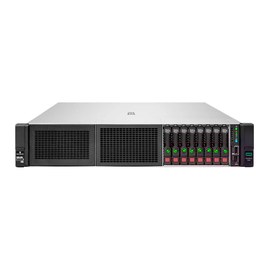
HPE StoreOnce 5260/5660 Controller Node LEDs – Front Panel (See Figure 1)
Table 1. HPE StoreOnce 5260/5660 controller node LED statuses
| Item | LED | Status |
| 1 | Power On/ Standby button and system power LED | Solid blue = Activated Flashing blue = Remote management in progress, iLO- based firmware upgrade in progress, iLO reset in progress, iLO service port activity or error Off= Deactivated |
| 2 | Health LED | Solid green = Normal Flashing amber = System degraded Flashing red = System critical |
| 3 | NIC Status LED | Solid green = Link to network Flashing green = Network active Off = No network activity |
| 4 | UID button/LED | Solid green = System on and normal operation Flashing green = Performing power on sequence Solid amber = Power button= initialized, system on standby Off = No power present |
SFF Disk Drives in HPE StoreOnce 5260/5660 System

StoreOnce 5260 and 5660 System SFF SSD Disk Drive LEDs (See Figure 1)
| LED | Status |
| Solid blue = Drive locate Flashing blue = Firmware is updating |
| Rotating green = Drive activity Off = No drive activity |
| Solid white = Do not remove Off = OK to remove |
| Solid green = Configured Flashing green = Transforming Flashing green/amber = Predictive failure and configured Flashing amber = Predictive failure and not configured Solid amber = Failed Off = Not configured |

Rear panel LEDs (See Figure 1)
| Item | Description | Status |
| 1 | UID LED |
|
| 2 | Status LED |
|
| 3 | Link LED |
|
| 4 | Power supply LEDs |
|
Network card LEDs
There are two LEDs adjacent to each Ethernet port if you have StoreOnce Optional Hardware Network cards installed.
Table 1. Network card LEDs
| Link | Amber = On. Link to the adapter is established and operating at maximum speed. The adapter is receiving power and the cable connection is good. Green = On. Link to the adapter is established and operating at less than maximum speed. The adapter is receiving power and the cable connection is good. Off. No link to the adapter is established. The adapter is not receiving power or the cable connection is faulty. |
| Activity | Flashing green = Ongoing network data activity. The adapter is sending or receiving network data. Off = No network data activity or no connection. |
Fibre Channel card LEDs
There are three vertical LEDs adjacent to each Fibre Channel port if you have StoreOnce Optional Hardware Fibre Channel cards installed.
| Table 1.32 Gb Fibre Channel card LEDs | |||
| 32Gb LED | 16Gb LED | 8Gb LED | Activity |
| Off | Off | Off | Power Off (OK) |
| On | On | On | Power on before or after software initialization. Awaiting HBA software initialization. |
| Flashing | Flashing | Flashing | Power on after software initialization. Link not initialized. |
| Alternately flashing | Alternately flashing | Alternately flashing | Software fault (OK) |
| Off | Off | On | Connected at 8 Gb/s |
| Off | Off | Flashing | Activity at 8 Gb/s (OK) |
| Off | On | Off | Connected at 16 Gb/s |
| Off | Flashing | Off | Activity at 16 Gb/s (OK) |
| On | Off | Off | Connected at 32 Gb/s |
| Flashing | Off | Off | Activity at 32 Gb/s (OK) |
Table 2. 16 Gb Fibre Channel card LEDs
| 16Gb LED | 8Gb LED | 4Gb LED | Activity |
| Off | Off | Off | Power Off (OK) |
| On | On | ON | Power on before or after initialization. Awaiting HBA software initialization. |
| Flashing | Flashing | Flashing | Power on after software initialization. Link not initialized. |
| Alternately flashing | Alternately flashing | Alternately flashing | Software fault (OK) |
| Off | Off | On | Connected at 4 Gb/s |
| Off | Off | Flashing | Activity at 4 Gb/s (OK) |
| Off | On | Off | Connected at 8 Gb/s |
| Off | Flashing | Off | Activity at 8 Gb/s (OK) |
| On | Off | Off | Connected at 16Gb/s |
| Flashing | Off | Off | Activity at 16 Gb/s (OK) |
Storage enclosure components and LEDs
Primera 600 LFF Storage enclosure LEDs (See Figures 1-3)

Figure 1. Power cooling supply (PCM) LEDs
Table 1. PCM LED statuses
| Item | LED | Statuses |
| 1 | UID | Blue solid = Locate active and/or safe to remove. Blue flashing = Locate active; do not remove component. |
| 2 | Health | Green solid = Power on, normal operation Green off= Power off |
| 3 | Fault | Amber solid= Power supply or Fan Fault Amber off = No fault, Normal operation |

Figure 2. Drive enclosure LEDs
| Item | Description | Status |
| 1 | Fault | Amber solid = Fault |
| 2 | Health/Status | Green solid = Normal operation, no fault |
| 3 | UID/Services | Blue solid= Locate active |
Disk enclosure (rear) and I/O module LEDs
The following LEDs and indicators are used to verify disk enclosure and I/O module operation.

Figure 3. Rear side of disk enclosure and I/O module LEDs
NOTE: LEDs 4 and 5 show the SAS ports on the disk enclosure. The right-most port (SAS port 3) is not used by any HPE StoreOnce Systems.
| Item | LED symbol | Function | Status | State |
| 1 |  | UID/Service | Blue solid | Locate active; safe to remove. |
| Blue flashing | Locate active; do not remove. | |||
| 2 |  | Health | Green flashing | Normal operation |
| 3 |  | Fault | Amber solid | Fault |
| Amber flashing | Fault | |||
| Amber off | No fault | |||
| 4 | N/A | SAS port Fault | Amber solid | Fault |
| Amber off | No fault | |||
| 5 | N/A | SAS Port Link | Green solid | N/A |
| 6 | Do not use | Green off | Port not linked | |
| 7 | N/A | Cage number/Error code | See I/O module error codes. |
Expansion shelf error messages
For hardware issues on HPE StoreOnce System enclosures, the HPE D3600/3700 Disk Enclosure Maintenance and Service Guide and HPE D6020 Disk Enclosure Maintenance and Service Guide are the primary source of information. Most error messages are reported in the StoreOnce Management Console with appropriate diagnostic messages. However, some problems are not explicitly recorded and you must check the 7-segment display on the rear of the enclosure to identify the error code.
This section contains a full list of error conditions applicable to HPE StoreOnce System enclosures.
| I/O module error codes | |
| Cage number/Error code | State |
| A4 | Redundant IOM turned off. |
| AF | Redundant I/O Module Absent |
| B0 | Generic expander error |
| B1 | Expander bootstrap task has failed. |
| B3 | Using default SAS address |
| B5 | Communication error with the partner expander |
| B6 | Expander firmware mismatch between the two I/O modules |
| B7 | Failed on ESP configuration |
| B8 | Expander composite image error |
| B9 | SAS cable hardware error |
| BA | SAS cable unsupported by HPE |
| BD | ESP communication error |
| BE | Incompatible firmware in local ESP |
| BF | Incomplete system identification |
| C0 | Temperature sensor generic error |
| C2 | Failure on getting data from temperature sensor |
| C3 | Warning temperature reached in temperature sensor |
| C4 | Critical temperature reached in temperature sensor |
| D2 | Module Absent - Power Supply A |
| D5 | Communication error - Power Supply A |
| DA | Power Loss - Power Supply A |
| DB | Power Loss - Power Supply B |
| E2 | Module Absent - Fan A |
| E3 | Module Absent - Fan B |
| E7 | Voltage Error - Power Supply 0 |
| E8 | Voltage Error - Power Supply 1 |
| E9 | Rotor failure - Fan A |
| EA | Rotor failure - Fan B |
| F4 | NVRAM backup failure on Top I/O module |
| F5 | NVRAM backup failure on Bottom I/O module |
| F7 | The zoning configuration between expanders do not match, example: multipath daisy chain |
| F8 | Drive inserted into incompatible bay |
Component replacement and safety guidelines
Before you begin, read the following guidelines to help you complete the component replacement successfully and safely.
Required tools
The following items are required for some replacement procedures:
- T-8 Torx screwdriver
- T-10 Torx screwdriver
- T-15 Torx screwdriver
- T-25 Torx screwdriver
- T-30 Torx screwdriver
- Phillips screwdriver
Component replacement guidelines

Removing a component significantly changes the air flow within the enclosure. Components must be installed for the enclosure to cool properly. If a component fails, leave it in place in the enclosure until a new component is available to install.
Use the following guidelines when replacing a component in the HPE StoreOnce System, or when using StoreOnce Capacity Upgrade Kits.
For the JBOD enclosure (600 LFF), components must be replaced one at a time. Replacing multiple parts at the same time is not supported.
- Before replacing a component, verify its status to ensure that it needs replacement. To verify component status, check the following for component health and location information:
- Hardware Monitoring (StoreOnce Management Console)
- Event Log (StoreOnce Management Console)
- System Information (iLO)
- Integrated Management Log (iLO)
- Status LEDs (Hardware)
- Parts can be damaged by electrostatic discharge. Keep parts in electrostatic containers until needed and ensure you are properly grounded when touching static-sensitive components.
- Hewlett Packard Enterprise recommends waiting until periods of low storage system activity to replace a component.
- When replacing components at the rear of the rack, cabling might obstruct access to the component. Carefully move any cables out of the way to avoid loosening any connections. In particular, avoid cable damage that might be caused by the following:
- Kinking or excessive bending.
- Disconnecting cables without capping. If uncapped, cable performance might be impaired by contact with dust, metal, or other surfaces.
- Placing removed cables on the floor or other surfaces, where they might be walked on or otherwise compressed.
Maintenance operations
Preparing for maintenance
Prerequisites
Notify users of the upcoming maintenance window.
About this task
Many of the maintenance procedures described in this guide require the system to be powered off. Before powering off, HPE recommends backing up the latest keystore.
Procedure
- Open the StoreOnce Management Console.
- On the main menu, select Settings.
- In the Security section, select the Key Manager panel.
- On the Key Manager screen, open the Actions menu and select Backup.
- On the Backup Configuration panel, enter the password information and click Backup.
Turning on Maintenance Mode to control Remote Support
About this task
HPE StoreOnce Remote Support uses STaTS to collect and send remote data from the StoreOnce System to HPE Support. If you have configured HPE StoreOnce Remote Data Collection on your system, turn on Maintenance Mode. Maintenance Mode prevents Remote Support from automatically opening support cases while you perform maintenance on the system.
NOTE: Event notification on StoreOnce GUI and email notifications to subscribed users will continue to be sent, even when maintenance mode is turned on.
Procedure
- On the main menu, select Settings.
- In the System section, click the Maintenance Mode panel.
- Toggle the Maintenance Mode button on.
Turning off Maintenance Mode to resume Remote Support
Procedure
- On the main menu, select Settings.
- In the System section, click the Maintenance Mode panel.
- Toggle off the Maintenance Mode button.
Maintenance Mode turns off automatically after 24 hours.
Powering off the system
Procedure
- Log in to the StoreOnce Management Console.
- On the main menu, select Settings.
- On the Settings screen, select Shutdown on the Actions menu.
If you have storage enclosures attached to the system, they must be powered off after the server. - Power off all storage enclosures as follows:
- StoreOnce 3660, 5260, and 5660 enclosures — power off by disconnecting main power.
Powering on the system
Procedure
- If you have storage enclosures attached to the system, power on the enclosures before powering on the server.
- Press the power button on the front of the HPE StoreOnce System.
Upgrade BIOS or hardware firmware components
Always use the StoreOnce Management Console to implement BIOS and hardware firmware component checks and updates. The StoreOnce software contains currently supported firmware updates.
NOTE: Do not upgrade BIOS or hardware firmware components individually using downloads from the HPE Support website.
Upgrading StoreOnce Systems
Prerequisites
- You have obtained the StoreOnce upgrade package (.star file). The upgrade package file is located where it can be accessed from the StoreOnce System.
- You are directly logged in to the StoreOnce System that you are upgrading. You cannot upgrade a federation member system from the federation lead system.
- You are logged in as Administrator.
On HPE StoreOnce 3660, 5260 and 5660 Systems, please follow these mandatory steps for offline storage expansion to work seamlessly:
- First, upgrade to the latest version of the StoreOnce software revision 4.3.4.
- Cleanly shut down the server node and all existing enclosures.
- Disconnect all power cables from the server and enclosures.
- Perform the storage expansion, remembering the numbered sequence required to connect the enclosures. Ensure that only necessary changes are made to complete the expansion.
- Connect back all of the SAS cables correctly the same order, following the configuration diagrams.
- Connect back the enclosure power cables only and wait for a few minutes until the enclosures are powered up.
- When the enclosures are powered up, connect the server power cables and power on the server.
Not following these instructions can lead to data unavailability or data loss.
iLO must be configured to use the Production security state. Using the iLO High Security state is not supported.
NOTE: When performing a software upgrade to StoreOnce 4.3.4, ensure that the iLO5 version is at 2.44 or later. The iLO version is in accordance with the restricted upgrade path to 4.3.4, from software versions 4.2.3 or later.
NOTE: Data Services may take longer to start than expected. Do not reboot the system unless the data services are in a  state.
Procedure
- On the StoreOnce Management Console main menu, select Settings.
- On the Settings screen, expand the Actions menu and then select Upgrade.
The Upgrade screen guides you through steps for:- Selecting and uploading an upgrade package.
- Validating the upgrade package.
- Upgrading the StoreOnce System.
Upgrading software
The current software version is displayed on the System Dashboard under System Information.
To find out if a later software release is available, check HPE Support at http://www.hpe.com/support/softwaredepot. If it is, download the software release and follow the instructions in the accompanying Release Notes to install the software.
Supported web browsers for the StoreOnce Management Console
Refer to HPE StoreOnce Support Matrix for up-to-date details on supported applications. See StoreOnce websites for the link to this resource.
Replace the system board
Find the step-by-step instructions for replacing the motherboard in the HPE ProLiant DL385 Gen10 Plus Server Maintenance and Service Guide.
The following activities are specific to HPE StoreOnce Systems:
- Review the StoreOnce PCIe card configuration, DIMM configuration, and SAS cabling before removing the motherboard. These components must be replaced in the same locations after replacing the motherboard.
- Back up your existing iLO 5 configuration so that you can restore your iLO 5 license and settings on the new system board.
- After replacing the motherboard and restoring internal components to their correct locations, reconfigure BIOS settings and iLO 5 settings during boot up, and then restore the iLO 5 configuration from backup.
- Review and update firmware, if necessary.
- After powering up, rewrite warranty serial numbers into BIOS.
Backing up the iLO configuration
Prerequisites
- Configure iLO Settings privilege.
- iLO is configured to use the Production security state. Backing up and restoring the configuration when iLO is configured to use the HighSecurity, FIPS, or CNSA security state is not supported.
About this task
All products are shipped with paper copies of the iLO 5 licenses. If you no longer have these licenses, and the board is still working for the iLO 5 web interface connection through its management Ethernet port, make a note of the license before you remove the motherboard.
If the iLO 5 connection is not working, contact HPE Support.
Procedure
- Log in to iLO through the web interface.
- Click Administration in the navigation tree, and then click Backup & Restore.
- Click Backup.
- Optional: To password protect the backup file, enter a password in the Backup file password box.
The password can be up to 32 characters long. - Click Download.
The file is downloaded and this activity is recorded in the event log.
The file name uses the following format:![]()

Identifying location of components on the system board
Procedure
Before replacing the motherboard, make a note of PCIe slot allocation and SAS cabling.
Motherboard and system maintenance switch
The system board for the following HPE StoreOnce Systems is the standard DL385 Gen10 Plus motherboard:
- HPE StoreOnce 3660
- HPE StoreOnce 5260
- HPE StoreOnce 5660
Use the default settings. The default value for all positions on the system maintenance switch is OFF.
See the HPE ProLiant DL385 Gen 10 Plus Maintenance and Service Guide for more information about replacing the system board.
DIMM locations
DIMM slots are numbered sequentially (1 to 16) for each processor. The supported Advance Memory Protection modes use the letter assignments for population guidelines.
The locations of DIMM slots are also shown on the StoreOnce hood label inside the server.
Table 1. DIMM slot locations
| Model | Processor | DIMM | Slots |
| HPE StoreOnce 3660 System | 1 | DIMM 1 | Ch. H, slot 1 |
| DIMM 3 | Ch. G, slot 3 | ||
| DIMM 14 | Ch. C, slot 14 | ||
| DIMM 16 | Ch. D, slot 16 | ||
| 2 | DIMM 1 | Ch. H, slot 1 | |
| DIMM 3 | Ch. G, slot 3 | ||
| DIMM 14 | Ch. C, slot 14 | ||
| DIMM 16 | Ch. D, slot 16 | ||
| HPE StoreOnce 5260 System | 1 | DIMM 1 | Ch. H, slot 1 |
| DIMM 3 | Ch. G, slot 3 | ||
| DIMM 10 | Ch. A, slot 10 | ||
| DIMM 12 | Ch. B, slot 12 | ||
| DIMM 14 | Ch. C, slot 14 | ||
| DIMM 16 | Ch. D, slot 16 | ||
| 2 | DIMM 1 | Ch. H, slot 1 | |
| DIMM 3 | Ch. G, slot 3 | ||
| DIMM 10 | Ch. A, slot 10 | ||
| DIMM 12 | Ch. B, slot 12 | ||
| DIMM 14 | Ch. C, slot 14 | ||
| DIMM 16 | Ch. D, slot 16 | ||
| HPE StoreOnce 5660 System | 1 | DIMM 1 | Ch. H, slot 1 |
| DIMM 3 | Ch. G, slot 3 | ||
| DIMM 5 | Ch. F, slot 5 | ||
| DIMM 7 | Ch. E, slot 7 | ||
| DIMM 10 | Ch. A, slot 10 | ||
| DIMM 12 | Ch. B, slot 12 | ||
| DIMM 13 | Ch. C, slot 13 | ||
| DIMM 14 | Ch. C, slot 14 | ||
| DIMM 15 | Ch. D, slot 15 | ||
| DIMM 16 | Ch. D. slot 16 | ||
| 2 | DIMM 1 | Ch. H, slot 1 | |
| DIMM 3 | Ch. G, slot 3 | ||
| DIMM 5 | Ch. F, slot 5 | ||
| DIMM 7 | Ch. E, slot 7 | ||
| DIMM 10 | Ch. A, slot 10 | ||
| DIMM 12 | Ch. B, slot 12 | ||
| DIMM 13 | Ch. C, slot 13 | ||
| DIMM 14 | Ch. C, slot 14 | ||
| DIMM 15 | Ch. D, slot 15 | ||
| DIMM 16 | Ch. D. slot 16 |
BIOS settings and iLO network configuration after replacing the motherboard
About this task
Configure the ROM-Based Setup Utility (RBSU) settings before connecting the Fibre Channel, network, and SAS cables to the server during the server POST sequence. The RBSU configuration must be completed before the system boots into the StoreOnce software.
Procedure
- Boot up the StoreOnce System and watch the local console; the iLO 5 IP addresses are shown (IPv4 and IPv6).
NOTE
If the iLO port is plugged into a network that provides DHCP, the acquired addresses will be shown here and you can connect to the network address in a web browser to configure iLO. If not, you can edit iLO 5 during bootup, as described later in this procedure.
- To access System Utilities, press F9 in the ProLiant POST screen, and then select System Configuration.
- Select BIOS/Platform Configuration (RBSU) — System Options.
- Change the RBSU settings, as shown in the tables in the next section.
- Press F10 to save. Then press ESC until the System Utilities menu is displayed.
- At this point, you can do one of the following:
- Select Reboot the System and confirm to proceed.
- Or, if there are no DHCP–assigned IP addresses, you can manually configure iLO using the local console. Select System Configuration.
- Select the iLO 5 Configuration Utility.
- Select Network Options.
- Configure your network settings and press F10 to save.
- Press ESC until you exit System Utilities and can continue with the system reboot.
- Restore the iLO license and configuration. See Restoring the iLO license and configuration .
- Use the StoreOnce Management Console to verify that the firmware on the new component is correct.
NOTE
Note the output after running firmware upgrade. It will advise if you need a system reboot or a cold reboot to install the new firmware revision successfully.
- After power-up, it is necessary to rewrite warranty serial numbers into the BIOS. Contact HPE Support for assistance in rewriting warranty serial numbers.
RBSU settings
Table 1. RBSU settings for HPE StoreOnce Gen4 Systems
| Top menu item | Sub menu 1 | Sub menu 2 | Current default state | Change to: |
| Boot options | Boot mode | UEFI Mode | No change | |
| Advanced Options | Advanced System ROM Option | Serial Number | Original server serial number | |
| Product ID | P55682-B21 (For 3660) P55683-B21 (For 5260) P55684-B21 (For 5660) | |||
| Date and Time | Date (mm/dd/yyyy) | As appropriate | ||
| Time (hh: mm: ss) | As appropriate | |||
| Time Zone | As appropriate | |||
| Time Format | Coordinated Universal Time (UTC) | No change | ||
| System options | USB Options | Internal SD Card Slot | Enabled | Disabled |
Restoring the iLO license and configuration
Prerequisites
- Configure iLO Settings privilege
- Administer iLO User Accounts privilege
- Ensure that an iLO backup file exists.
- Verify that the default iLO account credentials are available if you previously reset iLO to the factory default settings.
- Verify that the iLO security state you want to use is configured.
When you configure the FIPS and CNSA security states, iLO is reset to the factory default settings. If you do not configure these security states before performing a restore, the restored information is deleted when you update the security state.
Procedure
- Click Administration in the navigation tree, and then click Backup & Restore.
- Click Restore.
- Depending on your browser, click Browse or Choose File, and then navigate to the backup file.
- If the backup file is password protected, enter the password.
- Click Upload and Restore.
iLO prompts you to confirm the request. - Click Restore.
Replace the HPE Smart Array P408e-p controller and components
All HPE StoreOnce systems described within this guide use the HPE Smart Array P408e-p SR Gen 10 Controller for RAID.
The controller has an embedded cache module and is fitted with the HPE 96W Smart Storage Battery.
Replacement part numbers
Following are the replacement spare part numbers for the HPE P408e-p Smart Array controller and components:
- StoreOnce 3660
- HPE Smart Array P408e-p SR Gen 10 Controller (slot 6): 804405-B21
- 96W Smart Storage Battery: 871264-001
- StoreOnce 5260
- HPE Smart Array P408e-p SR Gen 10 Controller (slot 3 and slot 6): 804405-B21
- 96W Smart Storage Battery: 871264-001
- StoreOnce 5660
- HPE Smart Array P408e-p SR Gen 10 Controller (slots 3 and 6): 804405-B21
- 96W Smart Storage Battery: 871264-001
Internal SAS cabling
The internal SAS cabling is illustrated for the HPE StoreOnce systems.

Figure 1. Internal SAS cabling for HPE StoreOnce 3660 Systems
| Item | From | To |
| Orange cable | Smart Array P816i-a SAS port 1 | Port 1, LFF backplane |
| Blue cable | Smart Array P816i-a SAS port 2 | Port 2, LFF backplane |
| Yellow cable | Smart Array P816i-a SAS port 3 | Port 3, LFF backplane |

Figure 1. Internal SAS cabling HPE StoreOnce 5260 and 5660 Systems
| Item | From | To |
| Orange cable | Port 1, embedded RAID controller | Port 1, front drive cage (OS disks) |
| Blue cable | Port 2, embedded RAID controller | Port 2, front drive cage (OS disks) |
RAID controller failures
The StoreOnce System boots from the p408i (Smart Array) and the two small form factor OS disks in the server. If a catastrophic failure of the boot RAID controller occurs, the system will not boot. This failure may only be diagnosed from the server POST messages where the controller may report an error or a lockup code.
In these cases, contact HPE Support and provide information about the reported error code.
Other forms of non-catastrophic RAID controller failure, or failure of the P408e-p Smart Array RAID controller in the system, will be reported in the Event Log of the StoreOnce Management Console.
NOTE:
If RAID fails and the StoreOnce System is still functioning, you can also get information, including license keys, by generating a Support ticket.
Replace the RAID components
When replacing the P408e-p Smart Array controller, be sure to replace the card into the same slot from which it was removed. Make sure that the card is connected to the internal SAS data storage. If the system has been expanded, also connect the card to the external SAS storage.
To reduce the risk of personal injury or damage to the equipment, consult the safety information and user documentation provided with the server and the RAID component before replacing the component.
HPE Smart Array P408e-p Smart Array SR Gen10
The P408e-p Smart Array controller card is located in HPE StoreOnce 3660 Systems in PCIe slot 6, and is located in StoreOnce 5260 and 5660 Systems in PCIe slot 3 and 6.

Figure 1. Controller ports and connectors on an HPE P408e-p Smart Array card
Table 1.
| Item | Description |
| 1 | Controller backup power connector. |
| 2 | External x4 Mini-SAS HD port 2e. 1 |
| 3 | External x4 Mini-SAS HD port 1e. 2 |
1 External SAS ports 1e and 2e comprise the single Mini-SAS HD receptacle connector, which can accept either two Mini-SAS HD x4 plug connectors or a single Mini-SAS HD x8 plug connector.
2 External SAS ports 1e and 2e comprise the single Mini-SAS HD receptacle connector, which can accept either two Mini-SAS HD x4 plug connectors or a single Mini-SAS HD x8 plug connector.
HPE P408e-p Smart Array Controller and 96W Smart Storage Battery
StoreOnce 3660, 5260 and 5660 Systems now utilize the HPE P408e-p Smart Array Controller for RAID configuration instead of p1224 or p1228 RAID controllers. The RAID cache module is now embedded within the Smart Array controllers, and the Super Capacitor is now replaced by a 96W Smart Storage Battery.
The 96W Smart Storage Battery is directly connected to the motherboard and to all risers within the server, providing power to each connected Smart Array Controller.
Replacing the P408e-p Smart Array RAID controller card
About this task
The general procedure for replacing the P408e-p Smart Array RAID card is the same to access the attached 96W Smart Storage Battery. For more information, see the HPE ProLiant DL385 Gen10 Plus Server Maintenance and Service Guide.
Procedure
- Power off the HPE StoreOnce System.
- Observing the safety and anti-static procedures, remove all external cabling to the PCIe cards.
- Remove the cover from the HPE StoreOnce System, as described in the HPE ProLiant DL385 Gen10 Plus Server Maintenance and Service Guide.
The HPE StoreOnce System may have additional Network or Fibre Channel cards in PCIe slots 1, 2, 4 or 5. - Locate the required P408e-p Smart Array controller card (slot 3 or 6) and remove the PCI riser cage, as described in the HPE ProLiant DL385 Gen10 Plus Server Maintenance and Service Guide.
- Unclip the blue retaining latch on the PCIe card (1 and 2) and remove the P408e-p Smart Array controller card (3). See Figure 1.

- Disconnect the failed P408e-p Smart Array Controller from the Smart Storage Battery located on the riser.
- Install the new P408e-p Smart Array Controller and check that it is seated properly. Close the blue PCIe card retaining latch (2). See Figure 2.

- Reconnect the small black cable from the P408e-p Smart Array controller card to the riser.
![information]() NOTE: Reconnect the small black cable from the P408e-p controller card to the riser. This is essential for protecting the storage cache in the event of a power failure.
NOTE: Reconnect the small black cable from the P408e-p controller card to the riser. This is essential for protecting the storage cache in the event of a power failure. - Replace the PCIe riser cage and the server cover, as described in the HPE ProLiant DL385 Gen10 Plus Server Maintenance and Service Guide.
- Reconnect all external cables.
- Power on the HPE StoreOnce System.
Once rebooted, the HPE StoreOnce System automatically identifies the new RAID controller and remaps the existing disk storage volumes and enclosures to the controller. - Using the StoreOnce Management Console, check that the firmware on the new component is correct, and upgrade it, if necessary.


Disk replacement
Disk numbering
See Figures 1-2
This chapter describes how to replace individual disks within a RAID set.
For instructions on how to connect additional storage by adding a capacity upgrade enclosure to an HPE StoreOnce System, see the printed documentation supplied with the capacity upgrade.

Primera 600 LFF disk bay numbering
Disk bay numbering and initial configuration of the enclosure
The following drawing provides the numbering of the disk bays within the storage enclosure drawers. The drawing also shows the initial configuration of an enclosure with some disk bays populated. The base enclosure that comes with the system and each capacity upgrade enclosure is initially configured this way.
The disks in the capacity upgrade kits must be added to the storage enclosures in a specific order. Each drawer has a label that specifies the sequence in which each set of 11 disks must be installed.

RAID configuration
All HPE StoreOnce Systems are supplied with their base storage already configured for use.
Table 1. RAID configuration
| HPE StoreOnce model | Minimum number of disks | Notes |
| HPE StoreOnce 3660 | 10 x 8 TB | The StoreOnce 3660 uses RAID 6 (8+2). The 10 storage disks in the front server disk bays are in a RAID 6 (8+2) set. Two disks can be lost without loss of backup data. The hot spare disk is in bay 11 at initial configuration. |
| HPE StoreOnce 5260 | 12 x 16 TB | The StoreOnce 5260 uses RAID 6 (9+2) + 1 hot spare in externally connected SAS storage enclosures. Each external storage enclosure contains 12 storage disks in a RAID 6 (9+2) set + 1 hot spare. Two disks can be lost without loss of backup data. The hot spare disk is in bay 11 at initial configuration. The StoreOnce 5260 server node contains SSD disks for the operating system and data cache only. |
| HPE StoreOnce 5660 | 12 x 16 TB | The StoreOnce 5660 uses RAID 6 (9+2) + 1 hot spare in externally connected SAS storage enclosures. Each external storage enclosure contains 12 storage disks in a RAID 6 (9+2) set + 1 hot spare. Two disks can be lost without loss of backup data. The hot spare disk is in bay 12 at initial configuration. The StoreOnce 5660 server node contains SSD disks for the operating system and data cache only. |
- It is important to replace failed disks promptly.
Configure SNMP traps and email alerts to ensure that you are alerted to disk failures. If a disk failure occurs, you will receive notification immediately and can replace the disks. - The StoreOnce 5260 and 5660 systems both have SSD disks in the head of the server which are in a RAID 6 set with no spare. In the event of failure, you will need to replace the disk.
Hot spare disk and LEDs on HPE StoreOnce Systems
HPE StoreOnce 3660, 5260, and 5660 Systems include hot spare disks in the external enclosures. If one disk fails in a RAID set, a hot spare disk automatically takes it place until the failed disk is replaced. The behavior of the LEDs on the hot spare disk is as follows:
- Off: The LED is off on a hot spare disk until it becomes active due to the failure of another disk in the RAID set. It is flickering green when in use.
- On (green): The LED is solid green on the hot spare disk until it becomes active due to the failure of another disk in the RAID set. It is flashing green when in use.
NOTE:
HPE StoreOnce 3660, 5260, and 5660 systems use a feature called Predictive Spare Activation for improved storage fault tolerance. Predictive Spare Activation mode will activate a spare drive anytime a member drive within an array reports a predictive failure. The data is copied to the spare drive while the RAID volume is still healthy. Assigning one or more online spare drives to an array enables you to postpone replacement of faulty drives.
Ordering the correct replacement disk for a failed disk
Always quote the serial number and product number for the enclosure with the failed disk so that HPE Support can replace the correct part. For replacement disk part numbers, see Part numbers lists for replacement parts.
HPE strongly recommends replacing a failed disk with a fresh disk from the factory. Do not substitute a disk from another RAID set.
If there is a problem adding a Capacity Upgrade Kit for the first time, the whole kit must be replaced, not just the failed component. This requirement is different than capacity upgrade kits for older StoreOnce models, and is because StoreOnce Gen4 capacity upgrade kits are factory preconfigured for faster integration with no storage parity initialization performance impact.
Replacing a hot-plug hard disk
Procedure
- Identify the disk that has failed.
- Remove the disk. See Figure 1.

- Press the hard disk carrier button (1) to release the ejector lever.
- Pull out the disk carrier handle and slide the hard drive assembly out of the drive bay. Be sure to support the drive when pulling it out of the cage.
- Replace the failed disk with the new disk.
The new disk should be of the same type and have a compatible capacity as that of the original disk. - Push the hard drive assembly (1) into the drive bay until it stops, and then press the HDD carrier latch (2) inward until it clicks. See Figure 2.

- Check the status of the drives as follows:
- Log in to the StoreOnce Management Console.
- On the main menu, select Settings.
- In the Hardware section, click the Hardware Monitoring panel.
- Click the Storage tab, and click the expand icon (
![]() ) to display the components.
) to display the components. - Expand the Enclosures sections and subsections to display the appropriate Drives.


NOTE:
It may take several minutes for the status to report that the disk replacement has completed successfully and that the new disk is being rebuilt as part of the RAID group. During this time several alerts are generated reflecting the status of the physical disks and the logical storage system.
Rebuilding storage if multiple disks fail and a RAID set is broken
Prerequisites
This procedure requires Administrator level privileges.
About this task
This section explains how to rebuild your storage in the event of a complete data loss. Rebuilding your storage should be done under the guidance of HPE Support.

This procedure removes all configured local storage, and will run at any time, even if the storage is healthy. The procedure cleans up all file system configuration on all local storage, and locally backed up data will no longer be accessible.
The StoreOnce system configuration, licenses, and management interfaces will not be affected.
After the failed disks have been replaced, you must remove the old file system configuration and rebuild a new one as follows:
Procedure
- Log in to the StoreOnce Management Console.
- On the main menu, select Settings.
- In the Hardware section, click the Storage panel.
- On the Local Storage tab, expand the Actions menu (
![]() ) and select Unconfigure.
) and select Unconfigure. - Select the check box to acknowledge the data loss operation you are about to perform, and then click the Unconfigure button.
- Re-enter your password to authenticate, and then click the Unconfigure button.
The operation is complete when the Local Storage page reports No Configured Storage. - Rescan your local storage. Expand the Actions menu (
![]() ) and select Rescan.
) and select Rescan. - Reconfigure your storage. Expand the Actions menu (
![]() ) and select Configure.
) and select Configure.
 ) and select Unconfigure.
Optional Hardware
The HPE StoreOnce Systems support the addition of 10 and 25 GbE Network cards and 16 and 32 Gb Fibre Channel cards.
For more information and installation instructions, see HPE StoreOnce Optional Hardware Installation and Configuration Guide.
Error messages for optional hardware
Table 1. Error messages for Optional Hardware
| Short message | Error message | Recommended action |
| Unrecognized | Unrecognized Hardware | Remove and replace with correct hardware. |
| Unsupported | Hardware installed but not a supported model | Replace the card with a supported model or remove it. |
| Hardware Fault | Hardware installed but reporting fault | Contact Hewlett Packard Enterprise Support. |
| Load order | Hardware install in wrong order | Move the card to the correct location. |
| Hardware Missing | Hardware expected but not found Replace the card or use the Remove Cards option on the Optional Hardware | panel, and restart the system. |
| Hardware degraded | Hardware installed but in degraded state | Contact Hewlett Packard Enterprise Support. |
| Empty Slot | Empty slot | Install the optional hardware and try again. |
Table 2. Error messages for licensing
| Short message | Error message | Recommended action |
| Not Checked | Slot {x} could not be checked due to other errors | Resolve the hardware issues and try again. |
| No Hardware | Slot {x} does not contain any optional hardware | Install the optional hardware and try again. |
| Hardware Error | A hardware error is preventing a license being applied to Slot {x} | Resolve the hardware issues and try again. |
| Load Order | A license is available for Slot {x} but the preceding slot in the load order must be licensed first. | Install the correct licenses in order. |
| Unlicensed | Slot {x} is unlicensed | Install the license. |
Replace Optional Hardware cards
Replace a 10/25GbE SFP card with another 10/25GbE SFP card, a 10GbE-T card with another 10GbE-T card, a 16Gb FC card with another 16Gb FC card, and an 32Gb FC card with another 32Gb FC card.
If you install a replacement card of the same type and into the same slot, no reactivation or relicensing is required.
Use the following procedure before powering off and removing or moving cards. This procedure prevents invalid card alerts from being generated after you restart the system. For more information, see the HPE StoreOnce 3660, 5260 and 5660 Systems User Guide or the StoreOnce Management Console Online Help.
To install the replacement card, follow the instructions in the HPE StoreOnce Optional Hardware Installation and Configuration Guide.
Preparing to replace Optional Hardware cards
Procedure
- Log in to the StoreOnce Management Console.
- On the main menu, select Settings.
- In the System section, click the License Management panel.
- On the License Management screen, expand the Actions menu and select Remove Cards.
Fibre Channel card considerations
For those products that have Fibre Channel cards, the following VTL and StoreOnce Catalyst device configuration notes apply:
- If using only VTL over Fibre Channel, no further configuration is required when replacing the Fibre Channel card.
- The World Wide Port Name (WWPN) and World Wide Node Name (WWNN) of the StoreOnce Catalyst over Fibre Channel device that is presented on a StoreOnce Fibre Channel port currently uses the WWPN / WWNN of the FC card. StoreOnce generated WWPNs / WWNNs are not used. Replacing the FC card will result in a new Catalyst over Fibre Channel WWPN / WWNN. After replacing a FC card the StoreOnce user will need to rezone their clients with the new WWPN / WWNN. The replaced port will not be seen by clients until this rezoning is performed.
Removing and replacing a Fibre Channel/10GbE or 25GbE optical SFP
About this task
The SFP is on the rear of the server and serves as the port transceiver for connecting to the FC SAN, or 10GbE or 25GbE network. Make sure that you have the correct SFP for the connection type.
When the system is on, do not stare at the optical transceivers. Doing so could damage your eyes.
Procedure
- Disconnect the FC, 10GbE, or 25GbE optical cable.
- Lift the retaining clip and slide the SFP carefully out of the FC or Ethernet card port.
- Remove the replacement SFP module from its protective packaging.
When handling the SFP, do not touch the gold contact leads to prevent damage.
- Carefully slide the replacement SFP into the FC or Ethernet card port until fully seated.
- Close the retaining clip to secure the SFP in place.
- Place the failed SFP into the packaging for return to HPE.
- Reconnect the FC, 10GbE, or 25GbE optical cable to the SFP.
- Verify that the link status LED is correct.
Reinstall the product software
In the rare occurrence of a complete operating system failure, you may need to reinstall the product software using the StoreOnce Quick Restore ISO Image. This task is normally carried out on the recommendation and under the supervision of HPE Support.
The StoreOnce Gen4 Quick Restore process allows customers to recover their StoreOnce systems without losing backed up data, provided the storage is intact and operational.
Downloading the Quick Restore ISO image
About this task
Use the StoreOnce Quick Restore ISO Image to install the StoreOnce software image onto the StoreOnce appliance disks.
StoreOnce Gen4 Quick Restore is only supported using the same software version that is installed on the system being restored. Customers must download and use the matching software version of StoreOnce Gen4 Quick Restore image.
Procedure
- Navigate to the HPE Support Center at http://www.hpe.com/support/hpesc.
- Search the Support Center for the QR ISO for the StoreOnce system model.
- Click the link to the correct QR ISO image in the list.
- On the QR ISO image page, click the link Obtain software.
The system QR Image page opens in Software Depot. - Review the instructions and click Select.
- Sign in with HPE Passport, or create an account.
- Complete the form and select Yes, I have read and accept the the software license terms for this order.
- Click Next.
- On the Software downloads and licenses page, select the correct Quick Restore Image and click Download.
Creating a bootable Quick Restore USB memory stick
Prerequisites
- A 4 GB or greater USB 2.0 memory stick
- ISO to USB utility of your choosing
The HPE USB Key Utility for Windows is not supported with StoreOnce Gen4 Quick Restore ISO images.
Procedure
- Plug the USB memory stick into the computer containing the StoreOnce Quick Restore ISO Image.
- Using the ISO to USB utility, create the bootable QR USB memory stick with StoreOnce Gen4 QR image.
- Once all steps are completed, remove the USB stick from the computer.
Installing the software
Prerequisites
- The server is powered off.
- The power cord, network cables, and all expansion enclosures are attached to the StoreOnce server.
- If installing using QR USB stick, a keyboard and monitor are required.
- If installing using iLO, the iLO network port and web interface must be connected, configured, and accessible.
Procedure
- Insert the QR USB stick into a USB port, or connect the ISO image file using iLO Virtual Media.
- Power on the system and press F11 to load the One-Time Boot Menu.
- In the One-Time Boot Menu, scroll down and select the QR USB stick to boot.
From this point, the installation process proceeds automatically and performs the following actions, stopping only if issues are found:- Performs pre-installation hardware checks and firmware updates.
- Deletes the existing logical storage configuration on the server Operating System disks
- Creates a new logical storage partition on the server OS disks in a mirrored (RAID 1) configuration
- Installs the Operating System and reboots the server
- Restores the StoreOnce System configuration automatically on boot
After these actions finish, the process is complete.
- Log in to the StoreOnce Management Console as normal.
NOTE:
If issues are found during the Quick Restore preinstallation checks, resolve all issues displayed onscreen first and then retry the QR process.
Websites
General websites
Single Point of Connectivity Knowledge (SPOCK) Storage compatibility matrix
https://www.hpe.com/storage/spock
Storage white papers and analyst reports
https://www.hpe.com/storage/whitepapers
For additional websites, see Support and other resources.
Safety precautions


Retain and follow all product safety and operating instructions. Always refer to the documentation (printed or electronic) supplied with your product. If there is a conflict between this document and the product documentation, the product documentation takes precedence. To reduce the risk of bodily injury, electric shock, fire, and damage to the equipment, observe all warnings on the product and in the operating instructions.
General precautions
The installation and maintenance of products must be carried out by qualified personnel.
If the product sustains damage requiring service, disconnect the product from the AC electrical outlet and refer servicing to an HPE authorized service provider. Examples of damage requiring service include:
- The power cord, extension cord, or plug has been damaged.
- Liquid has been spilled on the product or an object has fallen into the product.
- The product has been exposed to rain or water.
- The product has been dropped or damaged.
- The product does not operate normally when you follow the operating instructions.
To reduce the risk of personal injury or damage to the product:
- Place the product away from radiators, heat registers, stoves, amplifiers, or other products that produce heat.
- Never use the product in a wet location.
- Avoid inserting foreign objects through openings in the product.
- Move products with casters carefully. Avoid quick stops and uneven surfaces.
Preventing electrostatic discharge
To prevent damaging the product, be aware of the precautions required when replacing the system or handling parts. A discharge of static electricity from a finger or other conductor may damage system boards or other static-sensitive devices. This type of damage may reduce the life expectancy of the device.
To prevent electrostatic damage:
- Avoid hand contact by transporting and storing products in static-safe containers.
- Keep electrostatic-sensitive parts in their containers until they arrive at static-free workstations.
- Place parts on a grounded surface before removing them from their containers.
- Avoid touching pins, leads, or circuitry.
- Always be properly grounded when touching a static-sensitive component or assembly.
Equipment symbols
The following symbols may be placed on equipment to indicate the presence of potentially hazardous conditions:
 | This symbol in conjuction with any of following symbols indicates the presence of a potential hazard. The potential for injury exists if warnings are not observed. Consult your documentation for specific details. |
| | This symbol indicates the presence of a hot surface or a hot component. If this surface is contacted the potential for injury exists.
|
| | This symbol indicates the presence of hazardous energy circuits of electric shock hazards. Refer all servicing to qualified personnel.
|
 | These symbols on power supplies or systems indicate that the equipment is supplied by multiple sources of power.
|
 | This symbol indicates the presence of a moving fan blade. If the spinning blades are contacted, the potential for injury exists.
|
 | This symbol indicates an area where potential hazards may exist.
|

Support and other resources
Accessing Hewlett Packard Enterprise Support
- For live assistance, go to the Contact Hewlett Packard Enterprise Worldwide website:
https://www.hpe.com/info/assistance - To access documentation and support services, go to the Hewlett Packard Enterprise Support Center website:
https://www.hpe.com/support/hpesc
Information to collect
- Technical support registration number (if applicable)
- Product name, model or version, and serial number
- Operating system name and version
- Firmware version
- Error messages
- Product-specific reports and logs
- Add-on products or components
- Third-party products or components
Accessing updates
- Some software products provide a mechanism for accessing software updates through the product interface. Review your product documentation to identify the recommended software update method.
- To download product updates:
Hewlett Packard Enterprise Support Center
https://www.hpe.com/support/hpesc
Hewlett Packard Enterprise Support Center: Software downloads
https://www.hpe.com/support/downloads
My HPE Software Center
https://www.hpe.com/software/hpesoftwarecenter - To subscribe to eNewsletters and alerts:
https://www.hpe.com/support/e-updates - To view and update your entitlements, and to link your contracts and warranties with your profile, go to the Hewlett Packard Enterprise Support Center More Information on Access to Support Materials page:
https://www.hpe.com/support/AccessToSupportMaterials
Access to some updates might require product entitlement when accessed through the Hewlett Packard Enterprise Support Center. You must have an HPE Onepass set up with relevant entitlements.
Remote support
Remote support is available with supported devices as part of your warranty or contractual support agreement. It provides intelligent event diagnosis, and automatic, secure submission of hardware event notifications to Hewlett Packard Enterprise, which initiates a fast and accurate resolution based on the service level of your product. Hewlett Packard Enterprise strongly recommends that you register your device for remote support.
If your product includes additional remote support details, use search to locate that information.
HPE Get Connected
https://www.hpe.com/services/getconnected
HPE Pointnext Tech Care
https://www.hpe.com/services/techcare
HPE Complete Care
https://www.hpe.com/services/completecare
Customer self repair
Hewlett Packard Enterprise customer self repair (CSR) programs allow you to repair your product. If a CSR part needs to be replaced, it will be shipped directly to you so that you can install it at your convenience. Some parts do not qualify for CSR. Your Hewlett Packard Enterprise authorized service provider will determine whether a repair can be accomplished by CSR.
For more information about CSR, contact your local service provider.
Documentation feedback
Documentation feedback Hewlett Packard Enterprise is committed to providing documentation that meets your needs. To help us improve the documentation, use the Feedback button and icons (located at the bottom of an opened document) on the Hewlett Packard Enterprise Support Center portal (https://www.hpe.com/support/hpesc) to send any errors, suggestions, or comments. All document information is captured by the process.
Documents / Resources
References

Download manual
Here you can download full pdf version of manual, it may contain additional safety instructions, warranty information, FCC rules, etc.
Advertisement


Need help?
Do you have a question about the StoreOnce 3660 and is the answer not in the manual?
Questions and answers