Extron electronics CrossPoint 300 Series User Manual
Hide thumbs
Also See for CrossPoint 300 Series:
- Specification sheet (2 pages) ,
- Quick start manual (5 pages)
Table of Contents
Advertisement
Advertisement
Table of Contents

Related Manuals for Extron electronics CrossPoint 300 Series


Summary of Contents for Extron electronics CrossPoint 300 Series
- Page 1 im Vertrieb von CAMBOARD Electronics CrossPoint 300 128 HVA CrossPoint 300 1616 HVA CrossPoint 300 Matrix Switchers CrossPoint 300 84, 88, 124, 128, 816, 168, and 1616 HV and HVA 68-521-10 Rev. A 12 04 www.camboard.de Tel. 07131 911201 ce-info@camboard.de Fax 07131 911203...
- Page 2 im Vertrieb von CAMBOARD Electronics Precautions Safety Instructions • English Warning This symbol is intended to alert the user of important operating and maintenance Power sources • This equipment should be operated only from the power source indicated on the product.
- Page 3 im Vertrieb von CAMBOARD Electronics Quick Start — CrossPoint 300 Matrix Switchers Installation Step 6 Plug the switcher and input and output devices Step 1 into a grounded AC source, and turn on the input If desired, mount the switcher in a rack. and output devices.
- Page 4 im Vertrieb von CAMBOARD Electronics Quick Start — CrossPoint 300 Matrix Switchers, cont’d RGBHV and Audio buttons select/deselect Save or recall a preset video and/or audio. The Audio LED blinks to 1. Save a preset — Press and hold the Preset indicate audio breakaway.
-
Page 5: Table Of Contents
im Vertrieb von CAMBOARD Electronics Table of Contents Chapter 1 • Introduction ....................... 1-1 About this Manual ......................1-2 About the Matrix Switchers ..................1-2 Definitions ..........................1-3 Features ........................... 1-4 Chapter 2 • Installation ......................2-1 Mounting the Switcher .................... - Page 6 im Vertrieb von CAMBOARD Electronics Table of Contents, cont’d Rear Panel Operations ....................3-37 Performing a system reset from the rear panel ............. 3-37 Performing a hard reset from the rear panel ..............3-38 Optimizing the Audio (HVA Switchers) ..............3-38 Troubleshooting ........................
- Page 7 im Vertrieb von CAMBOARD Electronics Appendix A • Reference Information ................A-1 Specifications ........................A-2 Part Numbers ........................A-5 CrossPoint 300 part numbers ................... A-5 Included parts ........................A-5 Optional accessories ......................A-5 Cables ..........................A-5 ........................A-5 Bulk cable ....................
- Page 8 im Vertrieb von CAMBOARD Electronics Table of Contents, cont’d 68-521-10 Rev. A 12 04 All trademarks mentioned in this manual are the properties of their respective owners. www.camboard.de Tel. 07131 911201 ce-info@camboard.de CrossPoint 300 Matrix Switchers • Table of Contents Fax 07131 911203...
-
Page 9: Chapter 1 • Introduction
im Vertrieb von CAMBOARD Electronics CrossPoint 300 Matrix Switchers Chapter One Introduction About this Manual About the Matrix Switchers Definitions Features www.camboard.de Tel. 07131 911201 ce-info@camboard.de Fax 07131 911203... -
Page 10: About This Manual
RGBHV video signals only, and HVA models for switching RGBHV video and two-channel stereo audio (balanced and unbalanced). The CrossPoint 300 Series have a video bandwidth of 300 MHz (-3 dB). All models can also switch RGBS, RGsB, RsGsBs, HDTV, component video, S-video, and composite video signals. -
Page 11: Definitions
im Vertrieb von CAMBOARD Electronics Class Room 101 Class Room 102 Extron CrossPoint 300 128 HVA Matrix Switcher 8 Outputs Extron DVS 204 Scaler Extron VSC 700 Scan Converter 12 Inputs Extron DVS 204 Scaler Extron RGB 109xi Interface Extron Cable Box DVS 204 Scaler... -
Page 12: Features
BNC connectors. They can also switch RGsB, RsGsBs, component/ HDTV, S-video, or composite video. Bandwidth — The CrossPoint 300 Series switchers provide a minimum of 300 MHz (-3 dB) video bandwidth, fully loaded. Audio inputs (HVA models only) — Input and output stereo audio inputs, balanced or unbalanced, on 3.5 mm, 5-pole captive screw terminals. - Page 13 im Vertrieb von CAMBOARD Electronics Operational flexibility — Operations such as input/output selection, setting of presets, and adjustment of audio levels can be performed on the front panel or via the RS-232/RS-422 link. The RS-232/RS-422 link allows remote control via a PC or control system. •...
- Page 14 im Vertrieb von CAMBOARD Electronics Introduction, cont’d www.camboard.de Tel. 07131 911201 ce-info@camboard.de CrossPoint 300 Matrix Switchers • Introduction Fax 07131 911203...
-
Page 15: Chapter 2 • Installation
im Vertrieb von CAMBOARD Electronics CrossPoint 300 Matrix Switchers Chapter Two Installation Mounting the Switcher Connections and Rear Panel Features www.camboard.de Tel. 07131 911201 ce-info@camboard.de Fax 07131 911203... -
Page 16: Mounting The Switcher
im Vertrieb von CAMBOARD Electronics Installation Installation, cont’d Mounting the Switcher The matrix switchers are housed in rack-mountable, metal enclosures with 19" rack ears. The amount of vertical rack space required for each switcher is as follows: • The CrossPoint 300 84, 88, 124, and 128 are in a 3U high enclosure. •... -
Page 17: Rgbhv Input And Output
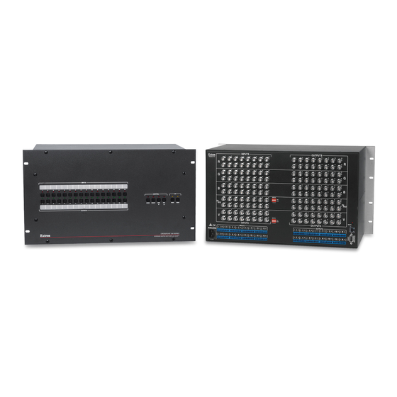
im Vertrieb von CAMBOARD Electronics Figure 2-2 shows the CrossPoint 300 1616 HVA. The CrossPoint 300 816 and 168 are housed in the same 6U enclosure, but have fewer input or output connectors to accommodate their smaller matrix sizes. INPUTS OUTPUTS RESET INPUTS... -
Page 18: Audio Input And Output (Hva Models Only)
im Vertrieb von CAMBOARD Electronics Installation, cont’d Audio input and output (HVA models only) By default, the audio ties follow the video ties. Audio breakaway, which can be activated via the front panel or under RS-232/RS-422 control, allows you to select from any one of the audio input sources and route it separately from its corresponding video source. -
Page 19: Rs-232/Rs-422
im Vertrieb von CAMBOARD Electronics Connections for balanced and unbalanced audio outputs — These 3.5 mm, 5-pole captive screw connectors output the selected unamplified, line level audio. Connect audio devices, such as an audio amplifier or powered speakers. See figure 2-5 to properly wire an output connector. Ring See caution Sleeve... -
Page 20: Reset Button
im Vertrieb von CAMBOARD Electronics Installation, cont’d Reset button Reset button — The Reset button initiates two levels of reset to the matrix switcher. Press and hold the button while the switcher is running or RESET while you power up the switcher for different reset levels. See Reset button in chapter 3, Operation, for details. -
Page 21: Chapter 3 • Operation
im Vertrieb von CAMBOARD Electronics CrossPoint 300 Matrix Switchers Chapter Three Operation Front Panel Controls and Indicators Front Panel Operations Rear Panel Operations Optimizing the Audio (HVA Switchers) Troubleshooting Configuration Worksheets www.camboard.de Tel. 07131 911201 ce-info@camboard.de Fax 07131 911203... -
Page 22: Front Panel Controls And Indicators
16 output buttons (figure 3-2). INPUTS CONTROL ENTER PRESET VIEW RGBHV AUDIO OUTPUTS CROSSPOINT 300 SERIES WIDEBAND MATRIX SWITCHER with ADSP™ Figure 3-1 — Front panel, CrossPoint 300 128 HVA ENTER PRESET VIEW RGBHV AUDIO CROSSPOINT 300 SERIES WIDEBAND MATRIX SWITCHER with ADSP™... -
Page 23: Definitions
im Vertrieb von CAMBOARD Electronics Definitions The following terms, which apply to Extron matrix switchers, are used throughout this manual: Tie — An input-to-output connection. Set of ties — An input tied to two or more outputs. (An output can never be tied to more than one input.) Configuration —... -
Page 24: Control Buttons
im Vertrieb von CAMBOARD Electronics Operation, cont’d Input and output label windows — These translucent panels can be removed and replaced to insert labels behind the panels. To remove a panel, insert the Phillips-head end of a Tweeker or small Phillips-head screwdriver into the hole in one end of the panel, and gently slide the tab at the edge of the panel out of the recess in the switcher housing. - Page 25 im Vertrieb von CAMBOARD Electronics Preset button and LED — The Preset button and LED have two primary functions (•) and three secondary (❏) functions: • Activates Save Preset mode to save a configuration as a preset and Recall Preset mode to activate a previously-defined preset. •...
-
Page 26: I/O Controls
im Vertrieb von CAMBOARD Electronics Operation, cont’d Esc ( ) button and LED — The Esc ( ) button and LED have two primary functions (•) and six secondary (❏) functions: • Cancels operations or selections in progress and resets the front panel button indicators. -
Page 27: Front Panel Operations
im Vertrieb von CAMBOARD Electronics Audio button and LED — The Audio button and LED have two primary functions (•) and five secondary (❏) functions • (HVA models only) Selects and deselects audio for a configuration that is being created or viewed. •... -
Page 28: Creating A Configuration
im Vertrieb von CAMBOARD Electronics Operation, cont’d Creating a configuration The current configuration can be changed using the front panel buttons. Change the current configuration as follows: Press the Esc button to clear any input LEDs, output LEDs, or control LEDs that are lit. -
Page 29: Example 1: Creating A Set Of Video And Audio Ties
im Vertrieb von CAMBOARD Electronics Example 1: Creating a set of video and audio ties The following steps show an example in which input 5 is tied to outputs 3, 4, and 8. The steps show the front panel indications that result from your actions. This example assumes that there are no ties in the current configuration. - Page 30 im Vertrieb von CAMBOARD Electronics Operation, cont’d Press and release the output 3, output 4, and output 8 buttons (figure 3-7). The entire set of ties can be canceled at this point by pressing and releasing the Esc button. The Esc LED flashes once. Press and release the Output 3, Output 4, and Output 8 buttons.
-
Page 31: Example 2: Adding A Tie To A Set Of Video And Audio Ties
im Vertrieb von CAMBOARD Electronics Example 2: Adding a tie to a set of video and audio ties The following steps show an example in which a new video tie is added to the current configuration. The steps show the front panel indications that result from your actions. - Page 32 im Vertrieb von CAMBOARD Electronics Operation, cont’d Press and release the output 1 button (figure 3-13). Press and release the Output 1 button. The LED blinks to indicate that the selected RGBHV input will be tied to this output. ENTER PRESE The Enter LED blinks to indicate the need to confirm the change.
-
Page 33: Example 3: Removing A Tie From A Set Of Video And Audio Ties
im Vertrieb von CAMBOARD Electronics Example 3: Removing a tie from a set of video and audio ties The following steps show an example in which an existing audio tie is removed from the current configuration. The steps show the front panel indications that result from your action. - Page 34 im Vertrieb von CAMBOARD Electronics Operation, cont’d Press and release the output 4 button (figure 3-19). Press and release the Output 4 button. The LED blinks to indicate that the selected RGBHV output will be untied. ENTER PRESE The Enter LED blinks to indicate the need to confirm the change.
-
Page 35: Viewing A Configuration
im Vertrieb von CAMBOARD Electronics Viewing a configuration The current configuration can be viewed using the front panel buttons. The View-Only mode prevents inadvertent changes to the current configuration. View-Only mode also provides a way to mute video and audio outputs (see Muting and unmuting video and/or audio on page 3-18. - Page 36 im Vertrieb von CAMBOARD Electronics Operation, cont’d Press and release the View button to enter View-Only mode. The View LED lights. To select both video and audio for viewing, if necessary, press and release the RGBHV button and the Audio button (figure 3-23). In this example, the Audio LED blinks to indicate audio breakaway (assuming you have performed example 1, 2, and 3).
- Page 37 im Vertrieb von CAMBOARD Electronics Press and release the RGBHV button to deselect RGBHV (figure 3-25). The output buttons for outputs that are tied to input 5 light to indicate audio ties (audio breakaway). RGBHV AUDIO Press the RGBHV The Audio LED remains button to delesect it.
-
Page 38: Muting And Unmuting Video And/Or Audio
im Vertrieb von CAMBOARD Electronics Operation, cont’d Muting and unmuting video and/or audio Individual outputs can be muted or unmuted as follows: Press the Esc button to clear any input LEDs, output LEDs, or control LEDs that are lit. Press and release the View button. Select video, audio, or both to mute or unmute by pressing the RGBHV button and/or the Audio button. - Page 39 im Vertrieb von CAMBOARD Electronics To select both video and audio for viewing and muting, if necessary, press and release the RGBHV button and the Audio button (figure 3-29). This example shows the indications that the front panel displays if example 1, example 2, and example 3 have been completed.
- Page 40 im Vertrieb von CAMBOARD Electronics Operation, cont’d Press and hold the Output 3 button and the Output 4 button (figure 3-31) for approximately 2 seconds until the LEDs light steadily. The output 3 and output 4 video and audio signals are unmuted. Press and hold the Output 3 and Output 4 button.
-
Page 41: Using Global Presets
im Vertrieb von CAMBOARD Electronics Using global presets The current configuration (configuration 0) can be saved as a preset in any one of 32 preset memory addresses. Preset locations are assigned to the input buttons and output buttons. Up to 20 or 32 (depending on the number of input and output buttons) presets can be selected from the front panel to be either saved or retrieved. - Page 42 im Vertrieb von CAMBOARD Electronics Operation, cont’d Press and hold the Preset button for approximately 2 seconds until the Preset LED blinks (figure 3-34). All input and output LEDs with assigned presets light. If you then save the configuration to a lit preset number, the configuration data at that preset location will be overwritten.
-
Page 43: Example 7: Recalling A Preset
im Vertrieb von CAMBOARD Electronics Example 7: Recalling a preset The following steps show an example in which a preset is recalled to become the current configuration in a CrossPoint 300 84. The steps show the front panel indications that result from your actions. Press and release the Esc button (figure 3-37). -
Page 44: Viewing And Adjusting The Input Audio Level (Hva Models)
RS-232/RS-422 control. Audio Inputs Low Audio Output Output Level Level Audio System CrossPoint 300 Series Switcher Audio Inputs No Noticeable Volume Differences Between Sources CD Jukebox High Audio Output Level Figure 3-41 — Audio gain and attenuation Press the Esc button to clear any input LEDs, output LEDs, or control LEDs that are lit. -
Page 45: Example 8: Viewing And Adjusting An Input Audio Level
im Vertrieb von CAMBOARD Electronics Press and release the Esc ( ) and View ( ) buttons to increase and decrease the audio level by 1 dB per each push of the button, or press and hold the button to change the level at a rate of 3 dB per second until the button is released or the upper or lower limit is reached. - Page 46 im Vertrieb von CAMBOARD Electronics Operation, cont’d Audio gain and attenuation settings CrossPoint 300 84, 88, 124, 128 HVA CrossPoint 300 816, 168, 1616 HVA Output LED Output LED View Esc View Esc = on, = blinking fast, = blinking slowly, = off www.camboard.de Tel.
- Page 47 im Vertrieb von CAMBOARD Electronics Press and release the input 5 button (figure 3-44). Figure 3-44 shows the current level (+8 dB) displayed on an 8-ouput-LED switcher, such as a CrossPoint 300 128 HV A. Press and release the Input 5 button. The LED lights.
- Page 48 im Vertrieb von CAMBOARD Electronics Operation, cont’d Press and release the View ( ) button once (figure 3-46) to decrease the input audio level by 1 dB. Press and release the View ( ) button several more times (figure 3-46) to decrease the input audio level by 1 dB per button push.
-
Page 49: Viewing And Adjusting The Output Volume (Hva Models)
im Vertrieb von CAMBOARD Electronics Press and release the Audio button (figure 3-48). Press the Audio button to exit audio mode. All input LEDs and output LEDs return to the unlit state. RGBHV AUDIO The Audio LED stops blinking and lights steadily. The RGBHV button lights. -
Page 50: Reading The Displayed Value
im Vertrieb von CAMBOARD Electronics Operation, cont’d Reading the displayed value This section is a detailed look at reading the output volume display on the switcher’s front panel. If you do not need read the exact value of the volume setting, skip this section. - Page 51 im Vertrieb von CAMBOARD Electronics Audio output volume settings CrossPoint 300 84, 88, 124, 128 HVA CrossPoint 300 816, 168, 1616 HVA Output dB of Input LED Output dB of Input LED volume attenuation volume attenuation 5.5% 5.5% 8.5% 8.5% 11.5% 11.5% 14.5%...
-
Page 52: Example 9: Viewing And Adjusting An Output Volume Level
im Vertrieb von CAMBOARD Electronics Operation, cont’d For example: When lit steadily, the Input 3 button indicates the following, depending on the number of input buttons the switcher has: Switchers with 12 input buttons — 47 dB of attenuation when compared to the Input 3 LED blinking quickly (48 dB to 50 dB of attenuation). - Page 53 im Vertrieb von CAMBOARD Electronics Press and release the output 1 button (figure 3-51). The input LEDs display the selected output's audio volume level. In this example, the lit input buttons indicate 40 to 41.5 percent of the applied audio input.
-
Page 54: Locking The Front Panel (Executive Mode)
im Vertrieb von CAMBOARD Electronics Operation, cont’d Figure 3-54 shows the same volume (61%) as in figure 3-53, but displayed on a 16-output-button switcher, such as a CrossPoint 300 1616 HVA. In this example, the input buttons display an audio gain level of –26 dB. = Lit LED, = Unlit LED, = Slow blinking LED... -
Page 55: Performing A System Reset From The Front Panel
im Vertrieb von CAMBOARD Electronics Performing a system reset from the front panel The front panel reset is identical to the rear panel system reset (see Performing a system reset from the rear panel on page 3-37) and to the ZXXX SIS command (see chapter 4, Programmer’s Guide). - Page 56 im Vertrieb von CAMBOARD Electronics Operation, cont’d Release the Control buttons. To change a value, press and release the button that relates to the desired value (figure 3-59). Press and release the LED(s) to configure the port as follows: Baud rate: Enter —...
-
Page 57: Rear Panel Operations
im Vertrieb von CAMBOARD Electronics Rear Panel Operations The rear panel has a Reset button that initiates two levels of matrix switcher resets. Press and hold the button while the switcher is running or while you apply power to the switcher for different reset levels. Performing a system reset from the rear panel This function is identical to the front panel system reset (see Performing a system reset from the front panel on page 3-35) without requiring you to power down the... -
Page 58: Performing A Hard Reset From The Rear Panel
im Vertrieb von CAMBOARD Electronics Operation, cont’d Performing a hard reset from the rear panel The hard reset function restores the switcher to the original factory default settings. All user files and settings are maintained. Perform a hard reset as follows: If necessary, turn off power to the switcher. -
Page 59: Troubleshooting
im Vertrieb von CAMBOARD Electronics Troubleshooting This section gives recommendations on what to do if you have problems operating the switcher, and it describes an actual image problem that Extron has encountered. General checks Ensure that all devices are plugged in and powered on. The switcher is receiving power if the Esc LED flashes one time when you push the Esc button. -
Page 60: Configuration Worksheets
im Vertrieb von CAMBOARD Electronics Operation, cont’d Configuration Worksheets Rather than trying to remember the configuration for each preset, use worksheets to record this information. Make copies of the blank worksheet on page 3-43 and use one for each preset configuration. The worksheet accommodates all of the matrix switcher models documented in this manual. -
Page 61: Worksheet Example 2: Drawing Ties
im Vertrieb von CAMBOARD Electronics Worksheet example 2: Drawing ties Figure 3-64 continues from worksheet example 1 by showing the video and audio ties that make up the configuration of preset 3. A solid ink line shows video ties, and a dashed pencil line shows the audio ties. In this example: •... -
Page 62: Worksheet Example 3: Test Configuration
im Vertrieb von CAMBOARD Electronics Operation, cont’d Worksheet example 3: Test configuration The A/V system in our fictional organization needs to be fine tuned on a regular basis. Figure 3-65 shows a typical test configuration, with an Extron video test generator (input 12) generating a test pattern to all monitors (outputs 1, 2, 3, 4, and 8). - Page 63 im Vertrieb von CAMBOARD Electronics www.camboard.de Tel. 07131 911201 ce-info@camboard.de CrossPoint 300 Matrix Switchers • Operation 3-43 Fax 07131 911203...
- Page 64 im Vertrieb von CAMBOARD Electronics Operation, cont’d This page was intentionally left blank. www.camboard.de Tel. 07131 911201 ce-info@camboard.de 3-44 CrossPoint 300 Matrix Switchers • Operation Fax 07131 911203...
-
Page 65: Chapter 4 • Programmer's Guide
im Vertrieb von CAMBOARD Electronics CrossPoint 300 Matrix Switchers Chapter Four Programmer’s Guide Host-to-Switcher Instructions Switcher-Initiated Messages Switcher Error Responses Using the Command/Response Table Command/Response Table for SIS Commands www.camboard.de Tel. 07131 911201 ce-info@camboard.de Fax 07131 911203... -
Page 66: Host-To-Switcher Instructions
The switcher-initiated messages are listed below (underlined). (C) Copyright 2004, Extron Electronics, CP 300 450 MAV IP, Vx.xx {day, date time} The switcher initiates the copyright message when it is first powered on. Vx.xx is the firmware version number. -
Page 67: Switcher Error Responses
im Vertrieb von CAMBOARD Electronics Innn Audxx The switcher initiates the Aud message when a front panel input audio level change has occurred. “nn” is the input number and “xx” is the dB level. Vmtnn•x The switcher initiates the Vmt message when a video output mute is toggled on or off from the front panel. -
Page 68: Command/Response Table For Sis Commands
im Vertrieb von CAMBOARD Electronics Programmer’s Guide, cont’d Command/Response Table for SIS Commands Symbol Definitions: = Carriage return/line feed = Carriage return (no line feed) • = Space = Escape key Input and output numbers in commands may be entered as either 1-digit, 2-digit, or 3-digit numbers. - Page 69 im Vertrieb von CAMBOARD Electronics Command/response table for SIS commands Command ASCII Command Response Additional description (host to switcher) (switcher to host) Create ties • Commands can be made back-to-back, with no spaces. For example: 1*1!02*02&003*003%4*16$. • The quick multiple tie and tie input to all output commands activate all ties simultaneously. •...
- Page 70 im Vertrieb von CAMBOARD Electronics Programmer’s Guide, cont’d Command/response table for SIS commands (Cont’d) Command ASCII Command Response Additional description (host to switcher) (switcher to host) Audio input gain and attenuation (HVA models) The set gain (G) and attenuation (g) commands are case sensitive. Set audio input gain to + dB value •Aud Example:...
- Page 71 im Vertrieb von CAMBOARD Electronics Audio volume adjustment settings dB of Output dB of Output dB of Output value value value attenuation volume attenuation volume attenuation volume 5.5% 38.5% 71.5% 8.5% 41.5% 74.5% 11.5% 44.5% 77.5% 14.5% 47.5% 80.5% 17.5% 50.5% 83.5% 20.5%...
- Page 72 im Vertrieb von CAMBOARD Electronics Programmer’s Guide, cont’d Command/response table for SIS commands (Cont’d) Command ASCII Command Response Additional description (host to switcher) (switcher to host) Save, recall, and directly write presets • If the user tries to recall a preset that is not saved, the matrix switcher responds with the error code E11.
- Page 73 im Vertrieb von CAMBOARD Electronics Command/response table for SIS commands (Cont’d) Command ASCII Command Response Additional description (host to switcher) (switcher to host) View ties, gain, mutes, and presets View RGBHV output tie & Example: 15& Input 27 RGBHV tied to output View video output tie Example: Input 2 video tied to output 7.
- Page 74 im Vertrieb von CAMBOARD Electronics Programmer’s Guide, cont’d Command/response table for SIS commands (Cont’d) Command ASCII Command Response Additional description (host to switcher) (switcher to host) View ties, gain, mutes, and presets (continued) View file directory filename1,date/time,length List user-supplied files. filename2,date/time,length filename3,date/time,length •...
-
Page 75: Chapter 5 • Matrix Software
im Vertrieb von CAMBOARD Electronics CrossPoint 300 Matrix Switchers Chapter Five Matrix Software Matrix Switchers Control Program Button-Label Generator www.camboard.de Tel. 07131 911201 ce-info@camboard.de Fax 07131 911203... -
Page 76: Matrix Switchers Control Program
By default, the Windows installation creates a C:\MTRX50 directory and places two icons (MATRIX Switcher+ Control Program and MATRIX Switcher+ Help) into a group or folder named “Extron Electronics”. The program was designed to control most Extron matrix switchers, but its operation is limited to the features and configuration of your switcher. -
Page 77: Using The Software
im Vertrieb von CAMBOARD Electronics Using the software Many items found in the Matrix Switcher+ Control Program are also accessible via front panel controls (see chapter 3, Operation) and under SIS control (see chapter 4, Programmer’s Guide). The Matrix Switcher+ Help Program provides information on settings and on how to use the control program itself. - Page 78 im Vertrieb von CAMBOARD Electronics Matrix Software, cont’d Figure 5-2 — Extron Matrix Switchers Control Program window (no ties) Figure 5-3 — Sample program window (with ties) • To set up audio in follow mode (audio and video have the same tie configuration), select the Follow box at the bottom of the window.
-
Page 79: Update Firmware
im Vertrieb von CAMBOARD Electronics Update firmware The firmware upgrade utility provides a way to replace the firmware that is coded on the switcher’s control board without taking the switcher out of service, opening the switcher enclosure, and replacing the firmware chip. Update the switcher firmware as follows: Visit the Extron web site, www.extron.com, select the CrossPoint 300 product category, and select the latest firmware file for download. - Page 80 im Vertrieb von CAMBOARD Electronics Matrix Software, cont’d The original factory-installed firmware is permanently available on the switcher. If the attempted firmware upload fails for any reason, the switcher reverts to the factory-installed firmware. Click the Open button. A status bar, which shows the progress of the upload, appears in the Firmware Loader window (figure 5-5).
-
Page 81: Windows Buttons, Drop Boxes, And Trash
im Vertrieb von CAMBOARD Electronics Windows buttons, drop boxes, and trash The buttons, drop boxes, and trash can on the right side of the program window perform the following functions: Power — Unavailable for these switchers. Executive mode — Allows you to lock out front panel operations, except for the view-only mode functions. -
Page 82: Audio-Input Configure Selection
im Vertrieb von CAMBOARD Electronics Matrix Software, cont’d Mute-Outputs settings — Displays the RGB Delay & Mute Adjust screen, from which you can mute video and/or audio for each input. Update firmware — Allows you to replace the firmware that is coded on the switcher’s control board without taking the switcher out of service, opening the switcher enclosure, and replacing the firmware chip set. -
Page 83: Preferences Menu
im Vertrieb von CAMBOARD Electronics Preferences menu Immediate changes — Causes configuration changes to take effect immediately. Hold/verify changes — Delays implementation of configuration changes until the Changes – Take button is pressed. Ties as lines — Displays ties as lines (figure 5-7). Figure 5-7 —... -
Page 84: Using Emulation Mode
Using the help system For information about program features, you can access the help program in any of the following ways: • From the Extron Electronics program folder or group, double-click on the Matrix Switcher+ Help icon (shown at right). •... -
Page 85: Button Label Generator
Matrix Switcher+ Control Program, or the C:\BUTTONS directory, if installed as a stand-alone program. The Button-Label Generator icon is placed in the “Extron Electronics” group or folder. Using the software To run the Button-Label Generator program, double-click on the Button-Label Generator icon (shown at right) in the Extron Electronics group or folder, and click OK when prompted. - Page 86 im Vertrieb von CAMBOARD Electronics Matrix Software, cont’d www.camboard.de Tel. 07131 911201 ce-info@camboard.de 5-12 CrossPoint 300 Matrix Switchers • Matrix Software Fax 07131 911203...
- Page 87 im Vertrieb von CAMBOARD Electronics CrossPoint 300 Matrix Switchers A ppendix A Reference Information Specifications Part Numbers Button Labels www.camboard.de Tel. 07131 911201 ce-info@camboard.de Fax 07131 911203...
-
Page 88: Specifications
im Vertrieb von CAMBOARD Electronics Reference Information Reference Information, cont’d Specifications Video Routing .......... 84 Series ....8 x 4 matrix 88 Series ....8 x 8 matrix 816 Series ....8 x 16 matrix 124 Series ....12 x 4 matrix 128 Series .... - Page 89 im Vertrieb von CAMBOARD Electronics Sync Input type ........RGBHV, RGBS, RGsB, RsGsBs Output type ........RGBHV, RGBS, RGsB, RsGsBs (follows input) Input level ........0.5 V to 5.0 V p-p, 4.0 V p-p normal Output level ........AGC to TTL: 4.0 V to 5.0 V p-p, unterminated Input impedance ......
- Page 90 im Vertrieb von CAMBOARD Electronics Reference Information, cont’d Control/remote — switcher Serial control port ......1 RS-232 or RS-422, 9-pin female D connector Baud rate and protocol ....9600 (default), 19200, 38400, 115200 baud (adjustable); 8 data bits, 1 stop bit, no parity Serial control pin configurations RS-232: 2 = TX, 3 = RX, 5 = GND RS-422: 1 = Tx+, 2 = TX-, 3 = RX+, 4 = RX-, 5 = GND...
-
Page 91: Part Numbers
im Vertrieb von CAMBOARD Electronics Part Numbers CrossPoint 300 part numbers Product Part # CrossPoint 300 1616 HVA 60-242-16 CrossPoint 300 1616 HV 60-242-15 CrossPoint 300 168 HVA 60-330-16 CrossPoint 300 168 HV 60-330-15 CrossPoint 300 816 HVA 60-396-16 CrossPoint 300 816 HV 60-396-15 CrossPoint 300 128 HVA 60-220-16... -
Page 92: Button Labels
im Vertrieb von CAMBOARD Electronics Reference Information, cont’d BNC-4 Mini HR Cable Part # BNC-4 Mini HR bulk, 500’ 22-032-02 BNC-4 Mini HR bulk, 1000’ 22-032-03 BNC-5 Mini HR Cable Part # BNC-5 Mini HR bulk, 500’ 22-020-02 BNC-5 Mini HR bulk, 1000’ 22-020-03 Plenum BNC-5 Mini HR Cable Part #... - Page 93 im Vertrieb von CAMBOARD Electronics www.camboard.de Tel. 07131 911201 ce-info@camboard.de CrossPoint 300 Matrix Switchers • Reference Information Fax 07131 911203...
- Page 94 im Vertrieb von CAMBOARD Electronics Reference Information, cont’d www.camboard.de Tel. 07131 911201 ce-info@camboard.de CrossPoint 300 Matrix Switchers • Reference Information Fax 07131 911203...
- Page 95 CAMBOARD Electronics Extron’s Warranty Extron Electronics warrants this product against defects in materials and workmanship for a period of three years from the date of purchase. In the event of malfunction during the warranty period attributable directly to faulty workmanship and/or materials, Extron Electronics will, at its option,...
- Page 96 PM Industrial Building 16 Ichibancho The Netherlands Singapore 368363 Chiyoda-ku, Tokyo 102-0082 Japan 714.491.1500 +31.33.453.4040 +65.6383.4400 +81.3.3511.7655 www.extron.com Fax 714.491.1517 Fax +31.33.453.4050 Fax +65.6383.4664 Fax +81.3.3511.7656 www.camboard.de Tel. 07131 911201 ce-info@camboard.de © 2004 Extron Electronics. All rights reserved. Fax 07131 911203...
Need help?
Do you have a question about the CrossPoint 300 Series and is the answer not in the manual?
Questions and answers