Extron electronics 100 User Manual
Hide thumbs
Also See for 100:
- User manual (5 pages) ,
- Quick start (2 pages) ,
- Quick start manual (2 pages)
Table of Contents
Advertisement
Quick Links
Advertisement
Table of Contents

Related Manuals for Extron electronics 100


Summary of Contents for Extron electronics 100
- Page 1 User’s Manual Matrix 100 Switcher...
-
Page 2: Table Of Contents
Illustrations: Figure 1-1. Rear view of a fully-populated Matrix Switcher ..........1-2 Figure 1-2. Matrix 100 Front Panel ................. 1-3 Figure 1-3. Block diagram of a Matrix 100 ..............1-4 Chapter 2 - Rear Panel Connections Multi-Output Connection ....................2-1 Genlock Connections ..................... - Page 3 Illustrations: Figure 4-1. IEC Power Panel: Power Switch, Fuse and Power Connectors ....4-1 Figure 4-2. Matrix 100 Cover has six screws ..............4-2 Figure 4-3. Front Panel Cable Connections and Battery Location ........4-3 Figure 4-4. Matrix 100, Face-up ..................4-3 Figure 4-5.
- Page 4 Appendix B - Part Numbers and Reference Related Part Numbers ....................B-1 Option Kit Part Numbers ................... B-1 BNC-4 Cables (High Resolution BNC Cables) ..........B-2 Matrix 100 Part Numbering System ................B-3 Manual number and status 68-199-01, Rev B 69-12...
- Page 5 _______ A Note, a Hint, or a Tip that may be helpful. ________ Possible Electrostatic Discharge (ESD) damage could result from touching electronic components. ________ Indicates word definitions. Additional information may be referenced in another section, or in another document. Extron • Matrix 100 • User’s Manual...
-
Page 6: Chapter 1 - Introduction To Matrix 100
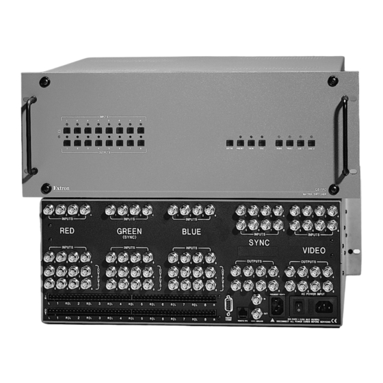
Matrix 100 User’s Manual Chapter One Introduction to Matrix 100 I/O Modules Configurations Standard Features Optional Features Matrix 100 Module Specifications Extron • Matrix 100 • User’s Manual... - Page 7 48 inputs by 48 outputs. This allows for multiple switching combinations. I/O Modules Matrix 100 Switchers are ordered for a specific application with a combination of I/O modules. Each module switches one type of video signal – one for red, one for blue, etc.
- Page 8 Genlock as many composite video signals as are installed in the switcher. RGB Delay Switching The Matrix 100 can be programmed (via RS-232) to delay switching the RGB video for 1 to 9 seconds after the sync is switched. This allows the display device to be in sync before the picture arrives, providing seamless switching of the RGBS signals when switching between various frequencies.
-
Page 9: Figure 1-2. Matrix 100 Front Panel
QuickSwitch™ Front Panel Controller (QS-FPC) The QuickSwitch Front Panel Controller (QS-FPC) provides local control of all Matrix 100 Switcher functions. It is supplied as an optional accessory to the Matrix 100 and is intended for users who wish to supplement normal RS-232 computer control with local or remote operator control. -
Page 10: Sample Configuration
Sample Configuration Figure 1-3 shows one example of the I/O modules that could be installed in six planes of a Matrix 100. See page 1-1 for I/O modules and possible configurations. For example, an 8 x 8 RGBS switcher requires: three 8 x 8 medium-resolution analog modules (MRAM) and one 8 x 8 sync module (Syn). - Page 11 Chapter 1 • Introduction to Matrix 100 Matrix 100 I/O Module Specifications Power . 90 - 260 VAC, 50/60 Hz, 60 Watts Dimensions . 17" W, 15" D, 6.8" H Shipping Weight . 22 lbs (10 kg) Operating Temperature . 0° C - 50° C Storage Temperature .
- Page 12 Chapter 1 • Introduction to Matrix 100 Audio Module, General Input Impedance . High Z (>10k ý, typical) Input Voltage Level . To 6 V p-p into 600 ý Output Impedance . Low, capable of driving 600 ý, balanced Output Level . Unity gain Connectors .
- Page 13 Chapter 1 • Introduction to Matrix 100 Notes: Extron • Matrix 100 • User’s Manual...
-
Page 14: Chapter 2 - Rear Panel Connections
Matrix 100 Switcher User’s Manual Chapter Two Rear Panel Connections Multiple Output Connections Genlock Connections RGB Input Connections Composite Video Input Connections S-Video Input Connections Audio Terminal Connections... -
Page 15: Multi-Output Connection
Chapter 2 • Rear Panel Connections Multi-Output Connection When using the Matrix 100 to switch different types of video signals, the signal output from the switcher is in the same format as the input. • RGB and Sync (composite or separate H&V) signals will pass through the RGB and Sync outputs •... -
Page 16: Genlock Connections
If not, a suitable adapter, or an Extron computer-video interface, should be used to adapt the device output to the BNC input of the Matrix 100. With the proper adapter, the RGB and Sync signals can be connected directly to the R, G, B, H, V inputs of the switcher. -
Page 17: Rgb Connections With Right & Left Audio
Figure 2-3 illustrates the Matrix 100 connections for switching RGB, or component video. Choose an input number and connect each cable from the source to the appropriate input on the Matrix 100. (The example shows Input #1.) Likewise, choose an output number and connect each of the three cables to a destination device. -
Page 18: Rgbs Connections With Right & Left Audio
Choose an input number and connect each of the four cables from the source to the appropriate input on the Matrix 100. (The example shows Input #2.) Likewise, choose an output number and connect each of the four cables to a destination device. -
Page 19: Rgbhv Connections With Right & Left Audio
Choose an input number and connect each of the five cables from the source to the appropriate input on the Matrix 100. (This example shows Input #2.) Likewise, choose an output number and connect each of the five cables to a destination device. -
Page 20: Composite Video Connections
NTSC and PAL are television or VCR type signals on a single coax cable, which may or may not have stereo audio. For this application, the Matrix 100 uses one Composite Video module, shown in Figure 2-6 in the right-most position. -
Page 21: S-Video Connections
Video module and the Chrominance (C) to the same input number on the second (right) Video module. If audio is used, connect the right and left audio source outputs to the right and left inputs on the back of the Matrix 100. See page 2-9 for details on audio connections. Output Connections Choose which Matrix 100 output number to use for the S-Video destination unit. -
Page 22: Figure 2-7. S-Video Connections With Right & Left Audio
Chapter 2 • Rear Panel Connections Figure 2-7. S-Video Connections with Right & Left Audio _______ Audio Connections may or may not be used. See page 2-9 for wiring. Extron • Matrix 100 • User’s Manual... -
Page 23: Audio Terminal Connections
Chapter 2 • Rear Panel Connections Audio Terminal Connections The rear of the Matrix 100 has two rows (16 sets) of audio connector pins, below the BNC connectors. The top row is for 8 inputs, and the bottom for 8 outputs. -
Page 24: Chapter 3 - Using The Front Panel Controller
Matrix 100 User’s Manual Chapter Three Using the Front Panel Controller I/O Module Select Input and Output Buttons Control Buttons Operating Examples Configuration Worksheets... -
Page 25: Quickswitch Front Panel Controller (Qs-Fpc) Operation
Thus, each input may have a tie (one output), or a “set of ties” (more than one output). At any one time, the active configuration of a Matrix 100 may have a set of ties per each available input. Any configuration (sets of ties) may be stored as a Preset. -
Page 26: I/O Module Select Buttons
The ESC button does not reset any configurations that have been entered. Preset – All current (active) configurations in the Matrix 100 may be stored as a Preset. To do this, press Preset twice (or hold the button for two seconds) and the Preset LED will blink. -
Page 27: Example #1: Configuring The Ties For Input 2
View – Pressing the View button lights its LED for to indicate a “view-only” mode to allow the display of the current Matrix 100 configurations. In this mode, pressing any input or output button will also light all LEDs for the input and output(s) that are part of that configuration. -
Page 28: Ties, Configurations And Presets
I/O module. For our own records, we chose the title “Test Patterns”. Because the matrix is 8x4, outputs 5 - 8 have been crossed out for this example. Matrix 200 Configuration Worksheet Extron • Matrix 100 • User’s Manual... -
Page 29: Extron • Matrix 100 • User's Manual
Chapter 3 • Using the Front Panel Matrix 200 Configuration Worksheet Matrix 200 Configuration Worksheet Extron • Matrix 100 • User’s Manual... -
Page 30: Chapter 4 - Hardware Installation
Matrix 100 Switcher User’s Manual Chapter Four Hardware Installation IEC Power Panel Removing the Matrix 100 Cover Installing QuickSwitch™ Front Panel RS-232/RS-422 Connections Installing Redundant Power Supply Installing I/O Modules... -
Page 31: Standard Power Supply
With this option, the Matrix 100 will automatically switch to the backup supply if the primary supply fails. If the Matrix 100 switches to the backup power supply, it continues to operate without interruption, and sends a command to the Host system to indicate a change in status. -
Page 32: Removing The Matrix 100 Cover
1. Turn off input power to the Matrix 100; disconnect power cord(s). 2. If the Matrix 100 is rack-mounted, remove it and place on a clean workspace. 3. Remove the six screws that hold the Matrix cover. Lift the cover-half straight up to expose the Main Controller board inside. -
Page 33: Replacing A Blank Panel With A Quickswitch Front Panel Controller
Figure 4-3. Front Panel Cable Connections and Battery Location 3. Remove the Blank Front and set it aside. 4. Position the QS-FPC on the front of the Matrix 100, with a spacer behind each screw. Install the four screws and dress washers (items &... -
Page 34: Changing The Main Fuse
Matrix. RS-232/RS-422 Communications The Matrix 100 can be controlled by a host system, through an RS-232 or an RS-422 interface. The interface allows the user to write programs to configure and automate the operation of the Matrix 100. This includes making changes dynamically when commanded by the host controller, as well as informing the host of the Matrix status. -
Page 35: Installing A Redundant Power Supply
Chapter 4 • Matrix 100 Hardware Installation Installing a Redundant Power Supply To install a redundant power supply in a Matrix 100, disconnect the power source, remove the Matrix from its rack mount, and place it on a clean workspace. Refer to page 4-2 to remove the cover. With the cabinet open, do the following: 1. -
Page 36: Adding An Audio Module
Chapter 4 • Matrix 100 Hardware Installation Adding an Audio Module _________ Do not do this procedure unless your Matrix 100 is up to date. 1. Remove the Matrix top cover (procedure on page 4-2). Tools for Installation: 3/16" flat screwdriver 2. -
Page 37: Figure 4-13. The Matrix Audio Module Before Installation
Chapter 4 • Matrix 100 Hardware Installation 5. Unpack the Audio Matrix module and locate the following: · The bracketed attachment is the power supply. · Two rows of female Phoenix audio connectors, eight in each row. Six pins per connector. -
Page 38: Figure 4-16. Plug The Ribbon Cables From Each Module To The Main Controller Board
14. If no other modifications are required, put the top cover back on the Matrix 100 and put it back in its working position. The new configuration will also appear in Request ID information sent to the Host system via the RS-232 port. -
Page 39: Installing I/O Modules In The Rear Panel
_______ Address switches are set according to the physical location. Back panel markings, such as "Sync" or "Video" should show what is installed in the Matrix 100. If an I/O module was added or changed to another type, peel off the black covering to show the proper module identification. -
Page 40: Figure 4-19. Module Differences
Note the orientation of the red stripe (pin 1) is to the right when looking from the front of the Matrix. 8. After rechecking all connections, put the cover on the Matrix 100 and secure it with the six screws. (See page 4-2.) -
Page 41: Installing Qs-Fpc Software Update
Chapter 4 • Matrix 100 Hardware Installation Installing QS-FPC Software Update 1. If the QS-FPC in mounted on the Matrix 100, see the procedure on page 4-2 to open the cabinet and then continue with step 2. ________ Electro-Static Discharge (ESD) can damage IC chips, even when it is not enough to be humanly detected (felt, heard or seen). -
Page 42: Chapter 5 - Windows® Control Software
Matrix 100 Switcher User’s Manual Chapter Five Windows® Control Software Installing the Software Operating Examples Using Help... -
Page 43: Extron Matrix Control Software
Communication between the computer software and the Matrix is done after connecting the computer to the RS-232/RS-422 Port on the rear panel of the Matrix 100. See Page A-1 for more information on this port. Installation of the software creates a Program Group (Windows 3.1) or a Folder (if Windows 95®) called “Extron Electronics”. -
Page 44: Figure 5-2. Control Program Example
“Caption”, allows the user to type in a name for that device. Click “Ok” to close the dialog box. Below is an example of a Matrix Control Program Window complete with assigned Icons, Captions and Ties, or connections. Figure 5-3. Configured Matrix Example Extron • Matrix 100 • User’s Manual... -
Page 45: Matrix 100/200 Help
To learn how to use Help, press F1 or choose Using Help from the Help menu The Matrix Control program communicates with the Extron Matrix 100 and 200 Switchers through the unit’s RS-232/422 port (defaults to 9600 baud, 8 bit, 1 stop, no parity). It presents the same functions found on the Front-Panel controller, but in an interactive graphical interface. -
Page 46: Extron • Matrix 100 • User's Manual
Chapter 5• Windows® Control Software Matrix 100 Switcher User’s Manual Appendix A RS-232 Programmer’s Guide Control Ports Host/Matrix Data Format Command Structure Communications Protocol Using Commands Extron • Matrix 100 • User’s Manual... -
Page 47: Control Ports
Main Controller board. The QS-FPC can also be dismounted from the front of the unit and used remotely at a distance of up to 100 feet. For remote operation, the QS-FPC is connected to the "Remote FPC" port, located on the rear panel. -
Page 48: Binary/Hex/Decimal Conversion Table
Binary/hex/decimal Conversion Table The table below shows how to convert data bytes from one numbering system to another. In Matrix 100 communications, all data bytes are identified by having bit 7 = 1, therefore it is not included in the computations. -
Page 49: Host-Initiated Communications Protocol
For example, the Host can send Commands to the Matrix to request data from, or send data to, the Matrix 100. After receiving a command, the Matrix 100 executes it and sends back a Response to the Host. The Response includes an error code, together with any requested data. -
Page 50: Matrix-Initiated Communications Protocol
Timing When Commands are sent to the Matrix 100 switcher, the response is delayed due to normal processing time. The response time has two components: RS- 232 or RS-422 bus delay and Matrix 100 processing time. Matrix 100 processing time is variable, depending on the length of the command and the matrix size. -
Page 51: Using Commands
Status Byte 3: Bit usage: S-Sec Where: StsB3, Bit 0 – Software Security status - 0 = locked; 1 = unlocked (available to user, when unlocked) StsB3 Bit-1 thru 6 are reserved (should be zero) Extron • Matrix 100 • User’s Manual... -
Page 52: Cmd1 (31H) - Report Id
_______ The string of data bytes in parentheses is shown for one switcher, or plane; there will be an additional string for each additional plane in the Matrix 100. They will be transmitted in the ascending order of their board addresses (plane #1 first). -
Page 53: Cmd2 (32H) - Turn Power On
1. Calculate 10x + y (decimal) (10x1 + 3 = 13d) 2. Convert to hex (13d = Dh) 3. Force bit 7 to become 8Dh The response is 34h, 80h, 8Dh, 80h, 80h, 04h Extron • Matrix 100 • User’s Manual... -
Page 54: Set (Tie) Connection Commands
Tie Menus used from the QS-FPC. Planes and Plane Maps When looking at the rear panel of the Matrix 100, the planes are counted from left-to-right, top-to-bottom. Presently, six planes (switching modules) are supported with hardware. Planes 1, 2, and 3 are reserved for Red, Green, and Blue modules. -
Page 55: Cmd5 (35H) - Set (Tie) Connection
3. Any, or all, valid planes may be specified in the same command. 4. Planes must be specified in ascending BdAd address order. (Plane 1 first; plane n last.) Response: CMD7, Erc, 80h, 80h, 04h Possible Ercs: C0 = Out of memory space Extron • Matrix 100 • User’s Manual... -
Page 56: Cmd8 (38H) - Download Status And Presets
Appendix A • RS-232 Matrix Programmer’s Guide CMD8 (38h) - Download Status and Presets The Host asks the Matrix 100 to send the contents of the specified preset. Same variables are used as in CMD7. Stored presets are numbered 1 thru 8. -
Page 57: Cmd12 (3Ch) - Mute Selected Outputs
Response: CMD13, Erc, Mute1, Mute2, ... MuteN, 80h, 80h, 04h Where: MuteX specifies planes to be muted for the output corresponding to the mute byte number. This uses the same format as PlnMap shown above. A-11 Extron • Matrix 100 • User’s Manual... -
Page 58: Cmd25 (49H) - Set Rgb Delay
Where: The “Dly” characters have the same significance as in previous command (CMD25). "N" represents the number of last available output, as determined by command CMD1. (Dly1 = output #1; Dly2 = output #2, etc.) A-12 Extron • Matrix 100 • User’s Manual... -
Page 59: Reports (Matrix-To-Host
Commands CMD5, 7, 9, 11, 12, and 25 will cause this report to be sent. Format:RPT1, Port#, 80h, 80h, 04h Where: Port# as follows ... host controller (RS-232/RS-422) standard front panel controller port secondary front panel controller port A-13 Extron • Matrix 100 • User’s Manual... -
Page 60: Appendix B - Part Numbers And Reference
Appendix A • RS-232 Matrix Programmer’s Guide Matrix 100 Switcher User’s Manual Appendix B Part Numbers & Reference Related Part Numbers Switcher Module Part Numbers BNC Cables Matrix 100 Numbering System Limited Warranty Extron • Matrix 100 • User’s Manual... -
Page 61: Option Kit Part Numbers
70-025-03 These kits include all the necessary parts, as well as instructions for a qualified person to add options to a Matrix 100. Chapter 2 of this manual also has some procedures for adding options. Extron • Matrix 100 • User’s Manual... -
Page 62: Specifications
The total cable diameter is 0.398". Extron recommends that when using signals with a scanning frequency of 15- 125 kHz and running distances of 100 feet or more, high resolution BNC cables should be used to achieve maximum performance. The following cables are... -
Page 63: Matrix 100 Part Numbering System
The diagram below illustrates how the part numbers are derived. All Matrix 100 part numbers begin with 60-182, the remaining digits are determined by other options. Use this diagram when ordering a new Matrix 100. _______ 1. S-Video uses two Composite Video modules.
Need help?
Do you have a question about the 100 and is the answer not in the manual?
Questions and answers