Extron electronics CrossPoint 450 Plus Series Setup Manual
Hide thumbs
Also See for CrossPoint 450 Plus Series:
- User manual (214 pages) ,
- Setup manual (21 pages) ,
- Specifications (2 pages)
Table of Contents
Advertisement
Quick Links
Advertisement
Table of Contents

Related Manuals for Extron electronics CrossPoint 450 Plus Series


Summary of Contents for Extron electronics CrossPoint 450 Plus Series
- Page 1 Setup Guide Matrix Switchers CrossPoint 450 Plus Series CrossPoint Ultra Series MAV Plus Series Matrix Switchers IMPORTANT: Refer to www.extron.com for the complete user guide, installation instructions, and specifications before connecting the product to the power source. 68-521-50 Rev. C...
- Page 2 Safety Instructions Safety Instructions • English Istruzioni di sicurezza • Italiano WARNING: This symbol, , when used on the product, is VVERTENZA: Il simbolo, , se usato sul prodotto, serve intended to alert the user of the presence of uninsulated ad avvertire l'utente della presenza di tensione non isolata dangerous voltage within the product’s enclosure that may pericolosa all'interno del contenitore del prodotto che può...
- Page 3 All trademarks mentioned in this guide are the properties of their respective owners. The following registered trademarks, registered service marks, and trademarks are the property of RGB Systems, Inc. or Extron Electronics (see the current list of trademarks on Terms of Use www.extron.com...
-
Page 5: Table Of Contents
Contents ........ 1 ......14 Introduction Remote Control About this Guide ......1 Selected SIS Commands .... 14 About the Matrix Switchers ... 1 Establishing a network (Ethernet) connection ..... 14 Connection timeouts ....15 ........3 Installation Number of connections ... 15 Rear Panel ........ - Page 6 CrossPoint / MAV Matrix Switchers> • Contents...
-
Page 7: Introduction
Introduction NOTES: • For more information on any subject in this guide, refer to the CrossPoint 450 Plus / CrossPoint Ultra / MAV Plus User Guide, available on the Extron website (www.extron.com). • In this manual, the term “CrossPoint”, when “450 Plus”... - Page 8 NOTES: • In this manual, the term “video model” refers to any CrossPoint or MAV Plus switcher that switches video. • In this manual, the term “audio model” refers to any CrossPoint or MAV Plus switcher that switches audio. Computer Ethernet Control System...
-
Page 9: Installation
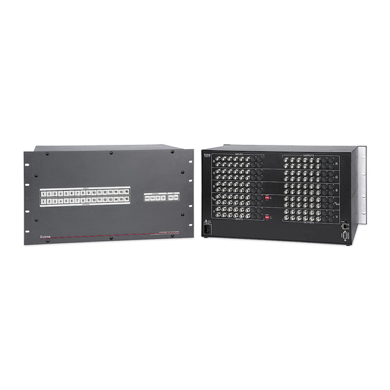
Installation Rear Panel NOTES: • The CrossPoint 450 Plus switchers are housed in enclosures that range from 8U to 10U (see figure 2) to support their different video format and matrix sizes. • The CrossPoint Ultra switchers are housed in enclosures that range from 3U to 6U to support their different video format and matrix sizes. - Page 10 NOTE: The MAV Plus switchers are housed in enclosures that range from 8U (see figure 3) to 2U (see figure 4) to support their different video format and matrix sizes. The arrangement of connectors and features in switchers with different form factors is different from what is shown in figure 2.
-
Page 11: Making Connections And Rear Panel Settings
Making connections and rear panel settings WARNING: Turn the input and output devices off and unplug their power cords. AVERTISSEMENT: Éteindre tous les appareils d’entrée et de sortie puis retirer les câbles d’alimentation. NOTE: Video connectors are grouped by video plane. - Page 12 Connections for balanced and unbalanced audio inputs (most audio models) — Connect balanced or unbalanced stereo audio inputs to these 5-pole captive screw connectors. Sleeve Ring Sleeve (s) Sleeve Ring Balanced Input Unbalanced Input (high impedance) (high impedance) Figure 5. Audio Input Connector Wiring Connections for balanced and unbalanced audio outputs (most audio models) —...
- Page 13 Remote port — If desired, connect a control system or computer to the rear panel Remote RS-232/RS-422 port NOTE: Serial port defaults: RS-232, 9600 baud, no parity, 8-bit, 1 stop bit, no flow control. RS-232 RS-422 Matrix Sizes: 84 — 1616 Matrix Sizes: All Models MAV Plus 248 / 328 A...
-
Page 14: Front Panel Configuration Port (Matrix Sizes Up To 1616, Mav Plus 32 A, And Mav Plus 248 A)
Front Panel Configuration Port (Matrix Sizes up to 1616, MAV Plus 32 A, and MAV Plus 248 A) CONTROL ENTER PRESET VIDEO AUDIO VIEW CONFIG ULTRA CROSSPOINT SERIES ULTRA-WIDEBAND MATRIX SWITCHER ADSP ™ WITH Figure 8. Front Panel Configuration Port Configuration port —... -
Page 15: Operation
Operation NOTE: The video selection button is labeled “RGBHV” on the CrossPoint switchers and “Video” on the MAV Plus switchers. The two labels are used interchangeably in this guide. Creating a Tie Press and release the button to clear any input button, output button, or control button indicators that may be lit. -
Page 16: Saving Or Recalling A Preset
Saving or Recalling a Preset Save a preset — Press and hold the Preset button until it flashes. Recall a preset — Press and release the button. Preset Save a Press and hold. PRESET PRESET preset 2 seconds Preset button blinks. Recall a Press and release. -
Page 17: Setting The Front Panel Locks (Executive Modes)
Setting the Front Panel Locks (Executive Modes) The matrix switcher has three levels of front panel security lock that limit the operation of the switcher from the front panel. The three levels are: Lock mode 0 — The front panel is completely unlocked. Lock mode 1 —... -
Page 18: Selecting Lock Mode 2 Or
Selecting Lock mode 2 or toggling between mode 2 and mode 1 NOTES: • If the switcher is in Lock mode 0 or mode 1, this procedure selects mode 2. • If the switcher is in Lock mode 2, this procedure selects mode 1. -
Page 19: Viewing And Adjusting The
Viewing and Adjusting the Audio Level Press the View button. Output buttons light for outputs that have no ties established. NOTES: • If the Audio button blinks, audio is broken away (switched separately from video). • If an output button blinks, that output is muted. To toggle mute on and off, press and hold the output button for 2 seconds. -
Page 20: Remote Control
Remote Control Selected SIS Commands • • Installing and Starting the Control Program • Accessing the HTML Pages Selected SIS Commands The switchers have Simple Instruction Set commands that you can use for operation and configuration. You can run these commands from a PC connected to either of the serial ports of the switcher or the Ethernet port. -
Page 21: Connection Timeouts
Connection timeouts The Ethernet link times out and disconnects after a designated period of time of no communications. By default, this timeout value is set to five minutes but the value can be changed. See the Connection Timeout command on page 20. NOTE: Extron recommends leaving the default timeout at five minutes and periodically issuing the Query (Q) command to... - Page 22 CrossPoint / MAV Matrix Switchers • Remote Control...
- Page 23 CrossPoint / MAV Matrix Switchers • Remote Control...
- Page 24 CrossPoint / MAV Matrix Switchers • Remote Control...
- Page 25 CrossPoint / MAV Matrix Switchers • Installation...
- Page 26 CrossPoint / MAV Matrix Switchers • Remote Control...
-
Page 27: Installing And Starting The Control
1 1 1 1 Follow the on-screen instructions. The installation program creates a Program Files Extron Matrix Switchers directory and an “Extron Electronics\Matrix Switchers” group folder. It installs the following four programs: • MATRIX Switcher+ Control Program • MATRIX Switcher+ Help •... -
Page 28: Starting The Program
Starting the program > > > Click Start Programs Extron Electronics Matrix > Switchers MATRIX Switcher + Control Pgm The Comm Port Selection window appears. Choose the comm (serial) port that is connected to the switcher or For a comm port, check the baud rate displayed NOTE: in the comm port selection window. -
Page 29: Accessing The Html Pages
If the switcher is password protected, enter the appropriate administrator or user password in the Password field. NOTE: The factory configured passwords for all accounts on this device have been set to the device serial number. In the event of a complete system reset, the passwords convert to the default, which is no password. - Page 30 Press the keyboard < > key. The switcher checks to see if Enter it is password protected. NOTE: The factory configured passwords for all accounts on this device have been set to the device serial number. In the event of a complete system reset, the passwords convert to the default, which is no password.
- Page 31 In no event will Extron Electronics be liable for direct, indirect, or consequential damages resulting from any defect in this product even if Extron Electronics has been advised of such damage.
- Page 32 Worldwide Headquarters: Extron USA West, 1025 E. Ball Road, Anaheim, CA 92805, 800.633.9876...
Need help?
Do you have a question about the CrossPoint 450 Plus Series and is the answer not in the manual?
Questions and answers