Table of Contents
Advertisement
Quick Links
Advertisement
Table of Contents

Related Manuals for Rexroth Indramat CLM1.4


Summary of Contents for Rexroth Indramat CLM1.4
- Page 1 Artisan Technology Group is your source for quality new and certified-used/pre-owned equipment SERVICE CENTER REPAIRS WE BUY USED EQUIPMENT • FAST SHIPPING AND DELIVERY Experienced engineers and technicians on staff Sell your excess, underutilized, and idle used equipment at our full-service, in-house repair center We also offer credit for buy-backs and trade-ins •...
- Page 2 CLM1.4 2 (4) Axis Positioning Control with Profibus Functional Description: LAP-01VRS DOK-CONTRL-CLM01.4LAP1-FK01-EN-P...
- Page 3 Date DOK-CONTRL-CLM01.4LAP1-FK01-EN-P 10.01 First release © 2001 Rexroth Indramat GmbH Copyright Copying this document, giving it to others and the use or communication of the contents thereof without express authority, are forbidden. Offenders are liable for the payment of damages. All rights are reserved in the event of the grant of a patent or the registration of a utility model or design (DIN 34-1).
-
Page 4: Table Of Contents
CLM01.4-LAP-01VRS Table of Contents Table of Contents System Setup The CLM at a Glance ........................1-1 Mechanical Data ..........................1-2 Saving Data............................ 1-3 System Overview ........................... 1-4 Important directions for use Appropriate use..........................2-1 Introduction ..........................2-1 Areas of use and application....................2-2 Inappropriate use ........................... - Page 5 Table of Contents CLM01.4-LAP-01VRS Display and Operating Devices General Information about the CTA ....................4-1 CLM Display..........................4-2 Description of the Input Keys ......................4-3 Data Entry Keys ........................4-3 Control Keys..........................4-3 Description of the Display Modes ....................4-4 Software Version / Status Diagnostics..................
- Page 6 CLM01.4-LAP-01VRS Table of Contents CPJ – Compare and Jump..................... 5-23 CPL - Clear Position Error ..................... 5-23 CPS - Compare and Set a Bit ....................5-24 CST - Clear Subroutine Stack Level..................5-24 CVT – Convert Variable <- -> Marker ..................5-25 FAK –...
- Page 7 Table of Contents CLM01.4-LAP-01VRS Logic Task Tabular View ..........................6-1 Load, Save, Set and Reset Assignments ..................6-1 Commands for Loading and Saving ..................6-1 Set and Reset Commands....................... 6-1 Logical Assignments ........................6-2 AND Logic ..........................6-2 OR Logic ..........................6-3 XOR Logic..........................
- Page 8 CLM01.4-LAP-01VRS Table of Contents Parameters General Information ........................8-3 System Parameters........................8-5 Ax00 Axis x Mode ........................8-5 Ax01 Axis x Feed Constant....................8-6 Ax02 Gear ..........................8-7 Ax03 Axis x Minimum Travel Limit Value................8-7 Ax04 Axis x Maximum Travel Limit Value................8-9 Ax05 Axis x Modulo Value ....................
- Page 9 Table of Contents CLM01.4-LAP-01VRS B007 Fieldbus Baudrate ...................... 8-30 B008 Fieldbus Formats......................8-31 B009 Reserved (Free) ......................8-31 B010 Cycle Time........................8-32 B011 Start Program Instruction - Task 2, Task 3 ..............8-32 B012 Start Program Instruction - Task 4, Task 5 ..............8-33 B013 Logic Task ........................
- Page 10 12 Terminal Connection Diagrams 12-1 12.1 Overview ............................12-1 12.2 CLM1.4 Dimensions........................12-2 12.3 Power Supply and System Signals for Axes 1 and 2..............12-3 12.4 System Signals for Axes 3 and 4 ....................12-3 12.5 System Signals for Axes 1 to 4 ....................12-4 12.6 Data Interface –...
- Page 11 VIII Table of Contents CLM01.4-LAP-01VRS 13 Installation Notes 13-1 13.1 General Information ........................13-1 13.2 Instructions for Using Cooling Units in Control Cabinets ............. 13-4 Correct Use of Cooling Units ....................13-4 13.3 Safety Instructions for Controls ....................13-6 General Information ....................... 13-6 Protection Against Contact with Electrical Parts..............
-
Page 12: System Setup
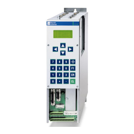
System Setup The CLM at a Glance The CLM is a compact, modular, 4-axis CNC control that can be combined with maintenance-free dynamic Rexroth Indramat AC Servo drives to create an efficient and economical control and drive system. Typical applications are: •... -
Page 13: Mechanical Data
System Setup CLM01.4-LAP-01VRS Mechanical Data • Parameter Operating Modes • Manual • Automatic • 4 axes Control Characteristics: • units can be defined in mm, inches and degrees • dimensions can be programmed as incremental or absolute • preselection of velocity in ‰ of Vmax •... -
Page 14: Saving Data
• The dimensions of the CLM control correspond to the modularly built Dimensions: Rexroth Indramat AC controllers, e.g. TVM and TDM. Depth x Width x Height = 330 x 105 x 390 mm • The CLM control weighs approximately 13.3 lbs. (6 kg). -
Page 15: System Overview
System Setup CLM01.4-LAP-01VRS System Overview Kompo1_AE.WMF Fig. 1-1: System Overview DOK-CONTRL-CLM01.4LAP1-FK01-EN-P... -
Page 16: Important Directions For Use
The user alone carries all responsibility of the risks. Before using Rexroth Indramat products, make sure that all the pre- requisites for appropriate use of the products are satisfied: •... -
Page 17: Areas Of Use And Application
The CLM1.4-LAP and every drive controller has to be programmed before starting it up, making it possible for the motor to execute the specific functions of an application. -
Page 18: Safety Instructions For Electric Drives And Controls
If you do not have the user documentation for your equipment, contact your local Rexroth Indramat representative to send this documentation immediately to the person or persons responsible for the safe operation of this equipment. -
Page 19: Hazards By Improper Use
Safety Instructions for Electric Drives and Controls CLM01.4-LAP-01VRS Hazards by Improper Use High voltage and high discharge current! Danger to life or severe bodily harm by electric shock! DANGER Dangerous movements! Danger to life, severe bodily harm or material damage by unintentional motor movements! DANGER High electrical voltage due to wrong... -
Page 20: General Information
CLM01.4-LAP-01VRS Safety Instructions for Electric Drives and Controls General Information • Rexroth Indramat GmbH is not liable for damages resulting from failure to observe the warnings provided in this documentation. • Read the operating, maintenance and safety instructions in your language before starting up the machine. - Page 21 Safety Instructions for Electric Drives and Controls CLM01.4-LAP-01VRS • Operation is only permitted if the national EMC regulations for the application are met. The instructions for installation in accordance with EMC requirements can be found in the documentation "EMC in Drive and Control Systems".
-
Page 22: Protection Against Contact With Electrical Parts
CLM01.4-LAP-01VRS Safety Instructions for Electric Drives and Controls Protection Against Contact with Electrical Parts Note: This section refers to equipment and drive components with voltages above 50 Volts. Touching live parts with voltages of 50 Volts and more with bare hands or conductive tools or touching ungrounded housings can be dangerous and cause electric shock. -
Page 23: Protection Against Electric Shock By Protective Low Voltage (Pelv)
Protection Against Electric Shock by Protective Low Voltage (PELV) All connections and terminals with voltages between 0 and 50 Volts on Rexroth Indramat products are protective low voltages designed in accordance with international standards on electrical safety. High electrical voltage due to wrong... -
Page 24: Protection Against Dangerous Movements
CLM01.4-LAP-01VRS Safety Instructions for Electric Drives and Controls Protection Against Dangerous Movements Dangerous movements can be caused by faulty control of the connected motors. Some common examples are: • improper or wrong wiring of cable connections • incorrect operation of the equipment components •... - Page 25 Safety Instructions for Electric Drives and Controls CLM01.4-LAP-01VRS Dangerous movements! Danger to life, risk of injury, severe bodily harm or material damage! ⇒ Ensure personal safety by means of qualified and tested higher-level monitoring devices or measures DANGER integrated in the installation. Unintended machine motion is possible if monitoring devices are disabled, bypassed or not activated.
-
Page 26: Protection Against Magnetic And Electromagnetic Fields During Operation And Mounting
CLM01.4-LAP-01VRS Safety Instructions for Electric Drives and Controls ⇒ Disconnect electrical power to the equipment using a master switch and secure the switch against reconnection for: - maintenance and repair work - cleaning of equipment - long periods of discontinued equipment use ⇒... -
Page 27: Protection Against Contact With Hot Parts
3-10 Safety Instructions for Electric Drives and Controls CLM01.4-LAP-01VRS Protection Against Contact with Hot Parts Housing surfaces could be extremely hot! Danger of injury! Danger of burns! ⇒ Do not touch housing surfaces near sources of heat! Danger of burns! CAUTION ⇒... -
Page 28: 3.11 Battery Safety
3-11 CLM01.4-LAP-01VRS Safety Instructions for Electric Drives and Controls 3.11 Battery Safety Batteries contain reactive chemicals in a solid housing. Inappropriate handling may result in injuries or material damage. Risk of injury by incorrect handling! ⇒ Do not attempt to reactivate discharged batteries by heating or other methods (danger of explosion and cauterization). - Page 29 3-12 Safety Instructions for Electric Drives and Controls CLM01.4-LAP-01VRS Notes DOK-CONTRL-CLM01.4LAP1-FK01-EN-P...
-
Page 30: Display And Operating Devices
CLM01.4-LAP-01VRS Display and Operating Devices Display and Operating Devices General Information about the CTA The CTA, which has a liquid-crystal display (LCD), is located on the front panel of the CLM. The display consists of 4 lines of 16 characters each. Below the display is a keypad with pressure-sensitive keys for data entry and manipulation of the display options. -
Page 31: Clm Display
Display and Operating Devices CLM01.4-LAP-01VRS CLM Display 22_anzei_AE.EPS Fig. 4-2: Map of Display Screens DOK-CONTRL-CLM01.4LAP1-FK01-EN-P... -
Page 32: Description Of The Input Keys
CLM01.4-LAP-01VRS Display and Operating Devices Description of the Input Keys Data Entry Keys The data entry keys allow for the input of program or parameter data and their functionality is shown depending on the type of data required. For inputting program data, if the cursor is in the 2 display line, these keys can be used to change the operational sign of a value (e.g. -
Page 33: Description Of The Display Modes
Display and Operating Devices CLM01.4-LAP-01VRS After pressing this key, the data shown on the display is transferred to the program memory or the parameter memory. After the data is transferred, the next instruction (current instruction number +1) or the next parameter (current parameter number +1) is displayed. -
Page 34: Software Version / Status Diagnostics
CLM01.4-LAP-01VRS Display and Operating Devices After turning on the control or after clearing a fault, the CLM either displays the software version or ’Parameter Input’ mode is active (see Operating Mode). The display mode can be changed at any time. In order to do this, the cursor must be returned to the base position: first line, third position. -
Page 35: Material Velocity
Display and Operating Devices CLM01.4-LAP-01VRS Operating Mode: Automatic Control Status: Immediate Stop at +24V C y c l S t a r t No Start Signal (Program not running) Control Status: Immediate Stop at +24V S t a r t A c t i v e Start Signal present (Program running) Control Status:... -
Page 36: Display: Inputs / Outputs / Marker Flags
CLM01.4-LAP-01VRS Display and Operating Devices Display: Inputs / Outputs / Marker Flags The bits of the selected byte are displayed. Every line allows Inputs / Outputs / Marker Flags to be displayed. The byte address can be changed by pressing . -
Page 37: Position Display
Display and Operating Devices CLM01.4-LAP-01VRS Position Display In this display mode, the user can display the current position by pressing Display Mode ’Length’: 1 A + 0 0 1 3 7 5 . 3 4 5 + 0 0 0 2 5 0 . 0 0 0 + 0 0 0 0 1 0 . - Page 38 CLM01.4-LAP-01VRS Display and Operating Devices Display Mode ’Remaining Distance’ 1 A + 0 0 0 5 0 0 . 0 0 0 + 0 0 0 0 5 0 . 0 0 0 + 0 0 0 0 0 0 . 0 0 0 4 A + 0 0 0 3 0 0 .
-
Page 39: Operation Data
4-10 Display and Operating Devices CLM01.4-LAP-01VRS Operation Data Automatic In this display mode, the program instruction that is currently being processed is displayed. The first 3 tasks (if programmed) are displayed simultaneously. If Tasks 4 and 5 are also programmed, these can be displayed by pressing The display in Automatic Mode is also valid for Manual Mode. -
Page 40: Program Input
4-11 CLM01.4-LAP-01VRS Display and Operating Devices Manual Display Mode ’Manual Mode’ M a n u a l I n i t . I n i t . I n i t . I n i t . A = Homed This information is shown when the applicable drive has been homed. -
Page 41: Parameter Input
4-12 Display and Operating Devices CLM01.4-LAP-01VRS Parameter Input Parameter Description M a x T r a v e l A x 0 4 1 2 3 4 5 6 . 7 8 0 Parameter Data Parameter Number Relationship to Axis This display mode is available only in the operating mode ’Parameter.’... -
Page 42: Writing The User Program
CLM01.4-LAP-01VRS Writing the User Program Writing the User Program Overview of All User Commands Command code and its meaning Page number ACC - Acceleration Change 5-10 AEA - Bit Set / Clear 5-10 AEO - Acceleration Override Command 5-11 AKN - Compare Bit 5-12 AKP - Compare Byte 5-13... - Page 43 Writing the User Program CLM01.4-LAP-01VRS PBK - Stop Motion (Positioning Break) 5-34 POA - Positioning, Absolute 5-35 - Positioning, Incremental 5-36 PSA - Positioning, Absolute with In-Position 5-36 - Positioning, Incremental with In-Position 5-36 REP - Jump on Max. Search Limit Reached 5-38 RMI - Registration Mark Interrupt 5-38...
-
Page 44: General Information
CLM01.4-LAP-01VRS Writing the User Program General Information The basic programming is pre-set, and the user has no external access to The programming language for the user program is a code similar to the BASIC programming language and was developed especially for use with this program. -
Page 45: Program Input
Writing the User Program CLM01.4-LAP-01VRS Program Input Input via the Keypad For programming via the keypad, the CLM must be in the display mode ’Program Input.’ Display mode program input Program instruction number User command Cursor position for editing the user command 0 1 2 3 P O I + 0 0 0 1 1 5 . - Page 46 CLM01.4-LAP-01VRS Writing the User Program If the cursor is placed after a command, it is moved to the first position in Cursor Movement the instruction number by pressing If the cursor is in line 2 or 3, it is moved to the position after the command by pressing .
-
Page 47: Loading Via The Serial Port
Writing the User Program CLM01.4-LAP-01VRS Loading via the Serial Port The program can be loaded via the serial port of any computer having an RS232C or RS485 interface. Parameters B002 and B003 control the activation and setting of the serial port. -
Page 48: Variables
CLM01.4-LAP-01VRS Writing the User Program correction of the problem is possible only at instruction ’0000’ for Tasks 1, 2, 3 and 4 for the instruction defined in Parameters B011 and B012. Exception: refer to ’Restart’ ("Functions" chapter) Variables The commands contain data which are contained in the instruction. These constants can also be changed on-line via the serial interface, but not from the user program. -
Page 49: Available Variables
Writing the User Program CLM01.4-LAP-01VRS The value of variable V603 is negative. An error message is generated. POI 1 -V604 V601 The content of variable V604 is negative. With the operational sign from the command, the feed length becomes positive. Available Variables The following variables are available for NC user programs: V600 to V999... -
Page 50: Axis Variables
CLM01.4-LAP-01VRS Writing the User Program Axis Variables The axis variables are read-only. They exist for each axis and are assigned to variables V1xx – V4xx. Definition Vx00 Absolute position value of motor encoder (IU) Vx01 Position Command Value Vx02 Reserved Vx03 Lag Distance Vx04... -
Page 51: Description Of Commands
5-10 Writing the User Program CLM01.4-LAP-01VRS Description of Commands ACC - Acceleration Change ACC V602 V600 V601 Deceleration in ‰ of the value programmed in Parameter Ax09 Acceleration in ‰ of the value programmed in Parameter Ax09 Axis: 1 to 4 Acceptance of the new acceleration and deceleration value is immediate. -
Page 52: Aea - Bit Set/Clear
5-11 CLM01.4-LAP-01VRS Writing the User Program AEA – Bit Set/Clear AEA Q1.02.3 V600 AEA Q1.02.3 0 = Off - Clear bit 1 = On - Set bit Bit: M2, M3, M4, Q1 Fieldbus : Q2.02.0-Q2.05.7 This command affects the status of the programmed bit. Hardware outputs are set at the beginning of the following cycle. -
Page 53: Akn - Compare Bit
5-12 Writing the User Program CLM01.4-LAP-01VRS Description of Override – Default value from Master Encoder 1: This function can only be activated using the AEO command if the axis in Parameter Ax00 is set to mode 0 (normal feed axis). Additionally, Master Encoder 1 (Parameter C000 to C003) must be set up correctly in the parameters. -
Page 54: Akp - Compare Byte
5-13 CLM01.4-LAP-01VRS Writing the User Program AKP – Compare Byte AKP M2.02 11022001 Bit field Byte: M0 – M5 I0 - I1 Q0 - Q1 Fieldbus : Q2, I2 This command represents an extension of the 'AKN' command. It can be used to verify that conditions have been met for a particular byte. -
Page 55: Ape - Byte Set/Clear
5-14 Writing the User Program CLM01.4-LAP-01VRS APE – Byte Set/Clear APE M2.02 21022001 Bit field Byte: M2, M3, M4, Q1 Fieldbus : Q2.02.0-Q2.05.7 This command represents an extension of the ’AEA’ command. It can be used to switch the bits in a byte. At the same time, each of the bits can be controlled independently. -
Page 56: Bac - Branch Conditional On Count
5-15 CLM01.4-LAP-01VRS Writing the User Program BAC – Branch Conditional on Count BAC V600 +1234 V603 BAC 0345 +1234 12345 Preset count Actual quantity offset Target location Like the COU command, this command allows the program to count events, process cycles, quantities, etc. First the quantity is incremented. -
Page 57: Bce - Branch Conditional On Bit
5-16 Writing the User Program CLM01.4-LAP-01VRS BCE – Branch Conditional on Bit BCE V602 M2.02.3 V600 BCE 0100 M2.02.3 0 = Low - Jump when status is ’0’ 1 = High - Jump when status is ’1’ Bit: M0 – M5 I0 - I1 Q0 - Q1 Fieldbus :... -
Page 58: Bio - Branch Conditional On Byte Compare
5-17 CLM01.4-LAP-01VRS Writing the User Program Examples: M2.03 M2.02 Starting bit Current status 1) Input : BIC 0500 11 M2.02.4 5 0 Selected bits: Binary value corresponds to decimal value 16 8 Target location : (16 + 0 + 4 + 2 + 0) = 22 22 * 11 + 500 = 0742 2) Input : BIC 0300 02 M2.02.2 8 0... -
Page 59: Bpa - Branch Conditional On Byte
5-18 Writing the User Program CLM01.4-LAP-01VRS Example: 0032_BIO_0123_M2.02_Q1.00 1 1 1 1 0 0 0 0 Compare Byte 1 1 1 1 0 0 0 1 0 Compare Byte 2 1 1 1 0 0 0 1 0 Result 1 1 X X 0 0 X X For results places with a content of 0 or 1, the condition is met. -
Page 60: Cid - Change Instruction Data
5-19 CLM01.4-LAP-01VRS Writing the User Program CID - Change Instruction Data CID V600 0 + V601 CID V600 1 +000000.100 Addition or subtraction of data Operational sign: + = amount is added to variable - = amount is subtracted from variable Assignment: 0 = Addition or subtraction 1 = Addition or subtraction;... -
Page 61: Clc - Clear Counter
5-20 Writing the User Program CLM01.4-LAP-01VRS Example: 0456 CIO I1.01.0 M2.02.0 5 The status of inputs I1.01.0 to I1.01.4 is copied to markers M2.02.0 to M2.02.4. Status of the Input Bits = Status of the Marker Bits = before after The program proceeds to the next instruction following the time period of one cycle. -
Page 62: Con - Continuous Operation
5-21 CLM01.4-LAP-01VRS Writing the User Program CON – Continuous Operation CON V600 V601 +V602 1 + 999 Speed in ‰ (001 to 999) of the programmed maximum speed (parameter AX06) Direction: + = forward / - = back (variable value with operational sign) 0 = Inactive - continuous operation OFF 1 = Active - continuous operation ON Axis: 1 to 4... - Page 63 5-22 Writing the User Program CLM01.4-LAP-01VRS Example: 0000 CLC 0002 0001 AEA Q1.00.4 0 0002 COU +00000 Q1.00.4 000010 0003 PSI 1 +000050.000 999 0004 WAI 01.000 0005 BCE 0001 Q1.00.4 0 0006 JST 0001 Positioning is executed ten times. Then, output Q1.00.4 is set and the system waits for a new start signal.
-
Page 64: Cpj - Compare And Jump
5-23 CLM01.4-LAP-01VRS Writing the User Program CPJ – Compare and Jump CPJ V600 V601 V602 V603 > CPJ V600 = +12345.123 1234.12 0400 > Target instruction Tolerance field Compare operand 2 Operational sign of compare operand 2 Compare conditions equal to (with tolerance field) >... -
Page 65: Cps - Compare And Set A Bit
5-24 Writing the User Program CLM01.4-LAP-01VRS CPS - Compare and Set a Bit CPS V600 V601 V602 M2.02.0 > CPS V600 = +12345.123 1234.12 M2.02.0 > Result bit M2, M3, M4, Q1 Fieldbus : Q2.02.0-Q2.05.7 Tolerance field Compare operand 2 Operational sign of compare operand 2 Compare conditions equal to (with tolerance field) -
Page 66: Cvt - Convert Variable <- -> Marker
5-25 CLM01.4-LAP-01VRS Writing the User Program Note: If all subroutine stacks have been cleared, issuing an ’RTS’ command after the ’CST X 0’ command will result in an RTS nesting ‘error.’ Example: Cst_bef_AE.WMF Fig. 5-7: Example Overview of Subroutine Stack Levels CVT –... - Page 67 5-26 Writing the User Program CLM01.4-LAP-01VRS Example: Convert the content of a variable to a BCD bit pattern V600 = -87654321.654321 CVT V600 M2.00 0 0 Marker Bit Number Value Comment Flag 7654 3210 M2.00 0010 0001 After decimal point M2.01 0100 0011 After decimal point...
- Page 68 5-27 CLM01.4-LAP-01VRS Writing the User Program I1.01.0 M2.03.4 04 Load value of the decade switch APE Q1.01 22220100 Select decade 2 10 WAI 00.02 Wait until level is stable I1.01.0 M2.04.0 04 Load value of the decade switch APE Q1.01 22221000 Select decade 1 10 WAI 00.02 Wait until level is stable...
-
Page 69: Fak - Length Scaling Factor
5-28 Writing the User Program CLM01.4-LAP-01VRS FAK – Length Scaling Factor FAK V600 V601 FAK 1 1.234567 Multiplication factor Input: from 0.000000 to 1.999999 Axis: 1 to 4 Positioning travel of the ’POA,’ ’POI,’ ’PSI’ and ’PSA’ commands is always the result of a preselected linear value or position and a multiplication factor. -
Page 70: Fol - Slave Axis
5-29 CLM01.4-LAP-01VRS Writing the User Program FOL – Slave Axis FOL V600 V600 – V601 FOL 1 –01.123456 Slave Factor Input of 0.000000 to 99.999999 Direction, with reference to master axis + or ` ´= in the same direction = in the opposite direction Status of the slave axis - in preparation ! 0 = Slave Axis OFF 1 = Slave Axis ON... -
Page 71: Hom - Home Axis
5-30 Writing the User Program CLM01.4-LAP-01VRS HOM – Home Axis HOM V600 Axis 1 to 4 This command produces an absolute measurement reference. What occurs basically corresponds to homing in Manual Mode. To accomplish this, Parameters Ax23 through Ax25 must be programmed accordingly. This command is not needed when the position is detected using multi- turn encoders, since they already generate an absolute measurement reference. -
Page 72: Jmp - Jump Unconditional
5-31 CLM01.4-LAP-01VRS Writing the User Program JMP – Jump Unconditional JMP V601 JMP 0123 Target instruction When it reaches this user command, the program jumps to the specified target location. This allows the programmer to jump directly to another part of the program. -
Page 73: Jst - Jump, Unconditional With Immediate Stop
5-32 Writing the User Program CLM01.4-LAP-01VRS JST – Jump, Unconditional with Immediate Stop JST V611 JST 0123 Target instruction With this command, the program jumps to the specified target location. However, program execution stops there. The program continues only when the voltage changes from '0' to '1' at the system input ‘Start.’ With the new start signal, the program continues at the target location. -
Page 74: Mat - Mathematics
5-33 CLM01.4-LAP-01VRS Writing the User Program MAT - Mathematics MAT V600 = V601 - + V602 MAT V600 = V601 - +123456.987654 operand Operational sign of the 2 operand Operation : Subtract Multiply Divide operand (is always a variable) Result (is always a variable) The calculation is transferred to a calculating unit. -
Page 75: Pbk - Stop Motion
5-34 Writing the User Program CLM01.4-LAP-01VRS PBK – Stop Motion PBK V600 Axis 1 to 4 This command can be used to interrupt positioning motions in progress. The relevant axis is brought to a standstill using the current deceleration value. Following deceleration, any remaining positioning travel is ignored. If continuous operation has been enabled using ’CON,’... -
Page 76: Poa - Positioning, Absolute
5-35 CLM01.4-LAP-01VRS Writing the User Program POA – Positioning, Absolute POA V600 + V601 V602 POA 1 +123456.789 Feed rate in ‰ (001 to 999) of the maximum velocity in the assigned parameter Absolute position given in IU (input units) Operational sign of the position (+/-) Axis 1 to 4 From its current position, the drive is moved to the programmed absolute... -
Page 77: Poi - Positioning, Incremental
5-36 Writing the User Program CLM01.4-LAP-01VRS POI – Positioning, Incremental POI V600 + V601 V602 POI 1 +123456.789 Feed rate in ‰ (001 to 999) of the maximum velocity given in the parameter (Parameter Ax06) Feed length in IU (input units) Direction of movement (+ = forward / - = back) Axis 1 to 4 The position setpoint is incremented or decremented by the amount of the... -
Page 78: Psi - Positioning Incremental With In-Position
5-37 CLM01.4-LAP-01VRS Writing the User Program The program proceeds to the next instruction when the drive unit has reached position +199.80 to +200.20. Note: Adjustment for the highest accuracy naturally takes place even after the program has gone on to the next instruction. The adjustment accuracy is therefore not dependent on the size of the position window. -
Page 79: Rep - Jump On Max. Search Limit Reached
5-38 Writing the User Program CLM01.4-LAP-01VRS REP – Jump on Max. Search Limit Reached REP V600 V601 V602 REP 0100 1 123456.789 Max. search path for ’SRM’ command in IU Axis 1 to 4 Jump to target location if search distance is exceeded This command is a supplement to the SRM command. - Page 80 5-39 CLM01.4-LAP-01VRS Writing the User Program The additional raster processing is initiated after detection of an input signal and movement of any offset distance for Axis 1. The rising edge of the pulse is evaluated. The motion program for this raster processing function is interrupted and continued later.
- Page 81 5-40 Writing the User Program CLM01.4-LAP-01VRS Programming Example: Task 1 0000 1 +000050.000 999 - Main Program 0001 0005 - Punching Unit 1 0002 1 +000025.000 999 0003 0009 - Punching Unit 2 0004 0000 - New Cycle Punching Unit 1 0005 Q1.00.0 1 - Punching Unit 1 ON...
-
Page 82: Rsv - Restart Vector
5-41 CLM01.4-LAP-01VRS Writing the User Program RSV – Restart Vector RSV 1 V600 1 0 0 1 1 RSV 1 0000 1 0 0 1 1 Free 1 = Restore status of outputs 0 = Status of outputs has not been restored Free Restore status from before interrupt (but not the output status) and terminate the Re-Start Program. -
Page 83: Rtm - Rotary Table Mode
5-42 Writing the User Program CLM01.4-LAP-01VRS RTM – Rotary Table Mode In preparation RTM 1 V600 RTM 1 Rotary table mode: 0 = mode accepted from Parameter Ax05 1 = shortest distance 2 = programmed direction >2 = no change in mode Axis 1 to 4 Rotary table must be preselected under the type of motion in Parameter Ax00 and the axis must be homed. -
Page 84: Rts - Return From Subroutine
5-43 CLM01.4-LAP-01VRS Writing the User Program RTS – Return from Subroutine As described for the ’JSR’ command, a subroutine must be concluded with an ’RTS’ return command. If several subroutine levels have been accessed in one program cycle, a return from a higher subroutine level leads first to the next lower subroutine level rather than directly back to the main program. -
Page 85: Sac - Set Abs. Position Counter
5-44 Writing the User Program CLM01.4-LAP-01VRS SAC - Set Abs. Position Counter SAC 1 0 +12345.678 Absolute position or offset in IU 0 = Absolute zero offset relative to the home position after homing 1 = Set new absolute position relative to the command position 9 = Clear ‘Homed’... -
Page 86: Set - Set Variable
5-45 CLM01.4-LAP-01VRS Writing the User Program SET – Set Variable SET V600 = + V601 SET V600 = +12345678.123456 Value Operational sign Variable Using this command, variables can be set from the program or copied from another variable. The program proceeds to the next instruction following the time period of one cycle. - Page 87 5-46 Writing the User Program CLM01.4-LAP-01VRS Offset dimension: The move to an offset dimension (referenced to the reference point) is accomplished immediately after detection of the reference point. It is also possible to limit and monitor the search travel until the reference marker is found (see also the ’REP’...
-
Page 88: Vcc - Velocity Change Command
5-47 CLM01.4-LAP-01VRS Writing the User Program Example of moving to a reference mark with offset programming: 0000 SRM 1 +000200.000 +500 I1.01.0 Ref2_bef_AE.WMF Fig. 5-23: Example of Moving to a Reference Mark with Offset Programming VCC – Velocity Change Command VCC V603 + V600 V601 0 V602 1 +123456.789... - Page 89 5-48 Writing the User Program CLM01.4-LAP-01VRS Example: The actual start position is 0 mm. 0000 1 +000100.000 999 - Move 100 IU, then proceed to next instruction 0001 1 000050.000 250 0 0 - after 50 IU, change to 25% velocity 0002 1 000075.000 500 0 0 - after 75 IU, change to 50% velocity...
-
Page 90: Veo - Velocity Override Command
5-49 CLM01.4-LAP-01VRS Writing the User Program Example: The actual start position is 0 mm. 0000 1 +000200.000 999 - Move to absolute position +200 IU 0001 1 +000100.000 500 1 1 - at position +100 IU, V = 50% 0002 1 +000180.000 100 1 1 - at position +180 IU, V = 10% 0003... - Page 91 5-50 Writing the User Program CLM01.4-LAP-01VRS This command produces a reduction in the velocity of all of the programmed traversing commands. With the ‘Override as factor’ function, the override value is multiplied by the programmed velocity from the commands. With the ‘Override as limit' function, the override value is multiplied by the programmed velocity from the parameter Vmax (Param.
- Page 92 5-51 CLM01.4-LAP-01VRS Writing the User Program Examples: ’VEO’ - Velocity Override 0000 0004 M2.02 21022222 - program selection 1; jump to Program A 0001 0006 M2.02 20122222 - program selection 2; jump to Program B 0002 0008 M2.02 21122222 - program selection 3; jump to Program C 0003 0000 - Input 0 selected;...
-
Page 93: Wai - Wait (Time Delay)
5-52 Writing the User Program CLM01.4-LAP-01VRS 2) Program B – Velocity limited to 70% from instruction number 0006 Veo2_bef_AE.WMF Fig. 5-28: VEO Command – Limit Velocity to 70% 3) Program C - Multiplication by factor of ’500’ from instruction number 0008 Veo3_bef_AE.WMF Fig. -
Page 94: Logic Task
CLM01.4-LAP-01VRS Logic Task Logic Task Tabular View Load, Save, Set and Reset Logical Assignments Assignments SETC ANDN XORN RESC Timer Other ms:= TOFF Fig. 6-1: Logic Task Commands Load, Save, Set and Reset Assignments Commands for Loading and Saving Loads the value of the operand Loads the negative value of the operand Assigns the current value to the operand Assigns the bit-by-bit negated value to the operand... -
Page 95: Logical Assignments
Logic Task CLM01.4-LAP-01VRS Logical Assignments AND Logic The ´AND Logic´ functions bit-by-bit. AND logic of the current value with the value of the operand ANDN AND logic of the current value with the bit-by-bit negated value of the operand Examples: AND Logic Type &... -
Page 96: Or Logic
CLM01.4-LAP-01VRS Logic Task OR Logic The ´OR Logic´ functions bit-by-bit. OR logic of the current value with the value of the operand OR logic of the current value with the bit-by-bit negated value of the operand Examples: OR Logic Type >=1 bool1 bool1:... -
Page 97: Xor Logic
Logic Task CLM01.4-LAP-01VRS XOR Logic The ´XOR Logic´ functions bit-by-bit. Exclusive OR logic of the current value with the value of the operand XORN Exclusive OR logic of the current value with the bit-by-bit negated value of the operand Examples: XOR Logic Type =2k+1... -
Page 98: Functions
CLM01.4-LAP-01VRS Functions Functions Operating Modes Parameter Mode Programming the parameters is possible only in this operating mode. When this mode is exited, the interactions between the parameters are reviewed and tested. In Parameter Mode, the power is turned off and all tasks are halted. The outputs and non-retained marker flags are cleared. - Page 99 Functions CLM01.4-LAP-01VRS Pertinent Parameters • Ax00, Application Type: • Ax31, Measuring wheel operating mode. • Ax16, Encoder difference monitoring • C000, Encoder Data of the Master Encoder 1 • C001, Encoder Type of the Master Encoder 1 • C002, Feed Constant of the Master Encoder 1 •...
-
Page 100: Velocity Override
CLM01.4-LAP-01VRS Functions Velocity Override The override function permits an infinitely variable reduction in the currently programmed velocity in Manual and Automatic Modes (exception: homing using the HOM command). Override via Analog Input The override is controlled via the connection of current to: AE1 ( X5/11 and X5/12 ) AE2 ( X5/14 and X5/15 ) AE3 ( X7/4 and X7/5 ) -
Page 101: Override Via Gray-Code Inputs
Functions CLM01.4-LAP-01VRS Override via Gray-code Inputs The override velocity can also be set using a step switch programmed with Gray code. This switch must be connected to inputs I1.01.4 to I1.01.7. This function is activated in Parameter B017 or using the ’VEO’ program command. -
Page 102: Override Via Binary-Code Inputs
CLM01.4-LAP-01VRS Functions Override via Binary-code Inputs The evaluation is handled via inputs I1.01.0 through I1.01.7. This function is activated separately for each axis in Parameter B017 or via the ’VEO’ program command. Input Number :I1.01.7 I1.01.0 binary value decimal value 128 64 32 16 8 The decimal values of all of the above inputs set to 1 are added together. -
Page 103: Vector Programming
Functions CLM01.4-LAP-01VRS Vector Programming Manual Vector This makes it possible to run a user program in Manual Mode. The vector program must be concluded with an RTS command (the stack is not changed). Note: In the manual vector program, no feeds can be programmed. When the operating mode is changed from ‘... -
Page 104: Interrupt Vector
CLM01.4-LAP-01VRS Functions Interrupt Vector With the interrupt vector, a program running in Automatic Mode in Task 1 can be interrupted externally at any time. The program sequence then continues at the interrupt program address (Parameter B015). There is no return to the interrupted main program. The interrupt vector can be invoked only in Automatic Mode. -
Page 105: Multitasking
Functions CLM01.4-LAP-01VRS Multitasking The control can process 5 cycles simultaneously (Task). The user can enter a program in each of these 5 tasks. In each task, one instruction (command) is processed within the NC cycle time. When programming Tasks 1 through 5, take note of the following: •... - Page 106 CLM01.4-LAP-01VRS Functions Task 3 is also enabled in Parameter B011, and the start instruction is Task 3 defined. Program execution of Task 3 begins automatically immediately after power-up (even in Manual Mode). Task 3 is deactivated only in Parameter Mode. Task 3 continues to run in the event of a fault or emergency stop.
-
Page 107: Slave Axis
7-10 Functions CLM01.4-LAP-01VRS Slave Axis If Slave Axis Mode is enabled, the slave axis executes all movements synchronously with the master axis. The slave axis is enabled separately for each axis in Parameter Ax00. There, the master axis is also selected. Possible following modes for Slave Axis 1: The master axis is Master Encoder 1 Possible following modes for Slave Axis 2:... -
Page 108: Mechanical Data
7-11 CLM01.4-LAP-01VRS Functions Mechanical Data Mechanical Transmission Elements Mechanical transmission elements are gearboxes and feed mechanisms between the motor shaft and the load. These data must be entered in order to perform the load-side conversion of the physical parameters for position, velocity and acceleration. -
Page 109: Modulo Function
7-12 Functions CLM01.4-LAP-01VRS Example: Ap5030f1_AE.WMF Fig. 7-5: Feed Constant Parameters Example: In the illustration above, the feed module would cover 10 mm per output revolution of the gear. The proper parameter settings for this would be : Ax01, Feed constant = 10 mm/rev Modulo Function If Parameter Ax00 is programmed for a rotary table, the modulo function is activated and all position data in the vicinity of the 0..modulo value are... -
Page 110: Decade Switch 'Ids01
7-13 CLM01.4-LAP-01VRS Functions Decade Switch ’IDS01’ The decade switch ’IDS01 is designed for installation in a front panel. This decade switch can be used to input lengths in input units ’IU’ and velocity values in percent into the CLM. Data transfer and power supply of the decade switch occur via a cable connection between the CLM and Connector 6 (serial interface). -
Page 111: Homing
7-14 Functions CLM01.4-LAP-01VRS Homing For absolute positioning of the motor with an incremental encoder, it is necessary to establish an accurate reference point using a positioning routine (homing). General Information Homing is possible in 2 operating modes: • Manual Mode - via input signal (see Parameter Ax23) •... -
Page 112: Option 1: Homing To A Home Switch
7-15 CLM01.4-LAP-01VRS Functions Option 1: Homing to a Home Switch 5324_hom_AE.WMF Fig. 7-8: Schematic of the Homing Routine Process Legend = Stop Position/Marker Pulse = Acceptance of New Position (Norming of the Absolute Position) V1 = Parameter - Homing Velocity V2 = 25% of the Parameter - Homing Velocity V3 = max. -
Page 113: Placement Of The Home Switch
7-16 Functions CLM01.4-LAP-01VRS 3.): If the carriage is positioned on the cam when the homing routine is initialized, it is moved off the cam at 1/4 the velocity designated in the parameter. Then, the same process as described in 2.) is followed. -
Page 114: Option 2: Homing Without A Home Switch
7-17 CLM01.4-LAP-01VRS Functions Option 2: Homing without a Home Switch 533_null_AE.WMF Fig. 7-9: Homing The first marker pulse is searched for at 10 increments/controller cycle. If it is found, a positioning move in the same direction occurs, to a position 1/32 revolution before the second marker pulse. -
Page 115: Position Loop Reset (Electrical Release)
7-18 Functions CLM01.4-LAP-01VRS 7.10 Position Loop Reset (Electrical Release) The function ’Position Loop Reset’ is activated by programming an input in Parameter Ax30. If it contains ’00.00.0,’ this function is not programmed. By placing 24V at the input ’Position Loop Reset,’ the function is activated. In addition, an output must be programmed. -
Page 116: 7.11 Restart
7-19 CLM01.4-LAP-01VRS Functions 7.11 Restart The Restart function continues a program interrupted by a loss of power, an error message or a switch from Automatic to Manual Mode. Restart is only possible following one of the situations mentioned above. The condition is that a program was running in Automatic Mode. For each of these situations, the current status of Task 1, 2, 4 and 5 (feedrate, absolute target position, status of the outputs, etc.) is saved temporarily. - Page 117 7-20 Functions CLM01.4-LAP-01VRS Notes DOK-CONTRL-CLM01.4LAP1-FK01-EN-P...
-
Page 118: Parameters
CLM01.4-LAP-01VRS Parameters Parameters PARAMETERS..................8-1 ..............8-3 ENERAL NFORMATION ............... 8-5 YSTEM ARAMETERS Ax00 Axis x Mode....................8-5 Ax01 Axis x Feed Constant.................8-6 Ax02 Gear......................8-7 Ax03 Axis x Minimum Travel Limit Value............8-7 Ax04 Axis x Maximum Travel Limit Value ............8-9 Ax05 Axis x Modulo Value................8-10 Ax06 Axis x Maximum Velocity............... - Page 119 Parameters CLM01.4-LAP-01VRS B018 Clear Outputs ..................8-36 B019 Memory Display ..................8-40 ............. 8-41 ASTER NCODER ARAMETERS C000 Master Encoder 1, Measuring Wheel Encoder Data......8-41 C001 Master Encoder 1, Measuring Wheel Encoder Type ......8-41 C002 Master Encoder 1, Measuring Wheel Encoder Feed Constant (VK).. 8-42 C003 Master Encoder 1, Measuring Wheel Offset.........
-
Page 120: General Information
CLM01.4-LAP-01VRS Parameters General Information The parameters and the user program are stored on a module card. This card has the description ’MOK19.’ Note: This data can be lost in the event of an error. Therefore, it is critically important to back up this data in another place outside the control. - Page 121 Parameters CLM01.4-LAP-01VRS The parameters are organized in 6 groups. The first group is the general Parameter Mode parameters. The next four groups are assigned to Axes 1 to 4. The data structure is identical for all four axes. In the last group, the parameters are for the additional encoders, e.g.
-
Page 122: System Parameters
CLM01.4-LAP-01VRS Parameters System Parameters Ax00 Axis x Mode M o d e A x 0 0 Test Mode (only for flying cutoff functionality) External Encoder 1 or 2 (for Measuring Wheel Mode) Master Axis Number: 1 to 4 (for synchronous/slave axis), Measuring Wheel = 5 Mode: 0 = Normal axis... -
Page 123: Ax01 Axis X Feed Constant
Parameters CLM01.4-LAP-01VRS Ax01 Axis x Feed Constant F e e d C o n s t a n t A x 0 1 0 0 5 0 . 0 0 0 0 0 Feed constant in IU Note: This is where the IU is defined IU = Input Unit This parameter describes the conversion from rotary to linear motion. -
Page 124: Ax02 Gear
CLM01.4-LAP-01VRS Parameters Ax02 Gear G e a r A x 0 2 1 2 3 4 1 2 3 4 Gear Output Gear Input A mechanical gear is often employed between the motor and the load. This parameter defines the gear ratio of the motor shaft to the output gear shaft for rotary applications with incremental encoders. - Page 125 Parameters CLM01.4-LAP-01VRS The travel range value is measured from the home position and is not calculated using the offset dimension Ax25. If a target position beyond the negative travel limit is stipulated for the drive, error message 50, 80, B0, E0 is generated. Example, when using an incremental encoder: When using an incremental encoder, depending upon programming, the home position shifts forward or backward from the home switch.
-
Page 126: Ax04 Axis X Maximum Travel Limit Value
CLM01.4-LAP-01VRS Parameters Example, when using an absolute encoder: For absolute encoders, the home position always shifts in the positive direction from the encoder home position. The minimum value is always input as a positive value. Limit_2_AE.WMF Fig. 8-3: Minimum Travel Range with Absolute Encoder Ax04 Axis x Maximum Travel Limit Value M a x T r a v e l... -
Page 127: Ax05 Axis X Modulo Value
8-10 Parameters CLM01.4-LAP-01VRS Ax05 Axis x Modulo Value M o d u l o V a l u e A x 0 5 0 1 2 3 4 5 . 7 8 9 0 = programmed direction (for rotary table) 1 = shortest path modulo value (in preparation) When the modulo format is set, the modulo value determines the numeric... -
Page 128: Ax06 Axis X Maximum Velocity
8-11 CLM01.4-LAP-01VRS Parameters Ax06 Axis x Maximum Velocity m a x . V e l o c i t y A x 0 6 1 2 3 4 5 6 . 7 8 9 Maximum velocity in IU/sec The maximum velocity input here is the highest velocity to be used for travel. -
Page 129: Ax08 Axis X Acceleration Rate
8-12 Parameters CLM01.4-LAP-01VRS Ax08 Axis x Acceleration Rate A c c e l R a t e A x 0 8 0 0 0 1 0 0 Acceleration in IU/sec The drive accelerates with the value set here. A different deceleration value can be programmed in Parameter Ax09. -
Page 130: Ax10 Jerk Constant
8-13 CLM01.4-LAP-01VRS Parameters Ax10 Jerk Constant J e r k C o n s t a n t A x 1 0 0 . 2 3 4 Time constant for acceleration change (sec) Input range: 0.000 to 1.024 0 = Jerk limiting inactive, constant acceleration The ’Time Constant for Acceleration’... -
Page 131: Ax11 Axis X Kv Factor
8-14 Parameters CLM01.4-LAP-01VRS Ax11 Axis x Kv Factor F a c t o r A x 1 1 0 1 . 2 3 Feedforward 0 = off 1 = on 1 = on + with interim values for command pulses 2 = Average of 2 values 3 = Average of... -
Page 132: Ax12 Axis X Drive Sensitivity
8-15 CLM01.4-LAP-01VRS Parameters Ax12 Axis x Drive Sensitivity D r i v e S e n s i t i v A x 1 2 0 1 0 0 0 0 9 . 0 Command voltage at maximum velocity in volts, with 1 decimal place (00.5 to 10.0) Max. -
Page 133: Ax13 Reserved (Free)
8-16 Parameters CLM01.4-LAP-01VRS Ax13 Reserved (Free) F r e e A x 1 3 Ax14 Axis x Position Monitoring Window M o n i t o r W i n d . A x 1 4 1 2 3 Q 1 . 0 0 . 0 Output ’Position error >... - Page 134 8-17 CLM01.4-LAP-01VRS Parameters The maximum position difference is calculated as follows: max. veloc ity in IU/ × Position Difference 1000 × Velocity (as in Ax12) VK(as in A x01) ± Max. Position D ifference × Factor Ax11) 1000 = Input Units = Factor Value / Parameter Ax11 = Feed Constant / Parameter Ax01 Fig.
-
Page 135: Ax15 Feed Angle Monitoring / Interrupt
8-18 Parameters CLM01.4-LAP-01VRS Example for ’Position Lag’: The programmed positioning command is not executed (no movement) because: a) the encoder cable is not connected b) the encoder cable is not defective The input value in Parameter Ax19 does not correspond with the encoder data (too large). -
Page 136: Ax16 Axis X Encoder Difference
8-19 CLM01.4-LAP-01VRS Parameters Ax16 Axis x Encoder Difference E n c . D i f f e r e n c e A x A x 1 6 Monitoring window in % (only for Measuring Wheel Mode) Ax17 Axis x Absolute Encoder Monitoring Window A b s . -
Page 137: Ax19 Axis X Encoder Data
8-20 Parameters CLM01.4-LAP-01VRS Ax19 Axis x Encoder Data E n c o d e r D a t a A x 1 9 0 1 2 5 0 0 0 0 0 Revolutions Pulses per revolution of the encoder Here, the number of pulses per encoder revolution is input. If an incremental encoder is used, the input of revolutions is meaningless. -
Page 138: Ax21 Axis X Drive Direction
8-21 CLM01.4-LAP-01VRS Parameters Ax21 Axis x Drive Direction D i r e c t i o n A x 2 1 1 = Turn external encoder (in preparation) 1 = Turn motor encoder 1 = Change direction Designated directions can be mixed (combined). Ax22 Axis x Absolute Encoder Home Position In preparation A b s . -
Page 139: Ax23 Axis X Homing I/O
8-22 Parameters CLM01.4-LAP-01VRS Ax23 Axis x Homing I/O H o m i n g I / O A x 2 3 I 1 . 0 0 . 0 I 1 . 0 0 . 1 Input: Home switch Input: Start homing Home Switch: I1.xx.x Input: Home switch for homing... -
Page 140: Ax25 Axis X Homing Offset
8-23 CLM01.4-LAP-01VRS Parameters Ax25 Axis x Homing Offset H o m i n g O f f s e t A x 2 5 + 1 2 3 4 5 . 6 7 8 Offset dimension For flying cutoff, this may be only a negative value. Ax26 Reserved F r e e A x 2 6... -
Page 141: Ax28 Position Window
8-24 Parameters CLM01.4-LAP-01VRS Ax28 Position Window In preparation P o s i t i o n W i n . A x 2 8 Q 1 . 0 0 . 0 1 2 3 4 . 5 6 7 Position window Output: Axis is in the last programmed position Ax29 Axis x Presignaling P o s... -
Page 142: Ax31 Axis X Measuring Wheel Mode
8-25 CLM01.4-LAP-01VRS Parameters Ax31 Axis x Measuring Wheel Mode W h e e l M o d e A x 3 1 I 1 . 0 0 . 0 Input: Activate measuring wheel This function is valid only when Measuring Wheel Mode is selected. Ax32 Axis x Various Functions F u n c t i o n s A x 3 2... -
Page 143: Ax34 Axis X Cut Vector
8-26 Parameters CLM01.4-LAP-01VRS Ax34 Axis x Cut Vector C u t V e c t o r A x 3 4 I 1 . 0 0 . 0 0 1 2 3 Start Instruction: Manual cut vector program Input: Immediate cut The function ’Immediate Cut’... -
Page 144: General Parameters
8-27 CLM01.4-LAP-01VRS Parameters General Parameters B000 Enable Axis E n a b l e A x i s B 0 0 0 Axis 4 0 = disabled 1 = enabled Axis 3 0 = disabled 1 = enabled Axis 2 0 = disabled 1 = enabled For an enabled axis, the corresponding parameter set Axxx must be... -
Page 145: B002 Rs Interface Format X6
8-28 Parameters CLM01.4-LAP-01VRS B002 RS Interface Format X6 F o r m a t B 0 0 2 0 0 9 6 0 0 Number of stop bits (1 or 2) Word length in bits (7 or 8) Parity check 1 = no parity 2 = even 3 = odd... -
Page 146: B003 Rs Interface Functions X6
8-29 CLM01.4-LAP-01VRS Parameters B003 RS Interface Functions X6 F u n c t i o n s B 0 0 3 0 0 0 0 0 0 Reserved Response delay in ms in RS485 Mode 000 = no delay 1 = in the event of a fault, an error message is sent automatically via the interface (RS 232 only). -
Page 147: B006 Fieldbus Time Monitoring
8-30 Parameters CLM01.4-LAP-01VRS B006 Fieldbus Time Monitoring F i e l d b u s T i m e M o n B 0 0 6 1 2 3 4 5 Maximum cycle time in ms Cyclic transmission of the process data via the fieldbus is monitored. If no new message is received within the maximum cycle time, the control unit generates the following error message: 37 Fieldbus Timeout... -
Page 148: B008 Fieldbus Formats
8-31 CLM01.4-LAP-01VRS Parameters B008 Fieldbus Formats F i e l d b u s F o r m a t s B 0 0 8 Fieldbus Slave Address 02 – 99 Fieldbus : 0 = enabled 1 = disabled 2 = Fieldbus without system control Readout: 0 = Word, Long word 1 = Byte... -
Page 149: B010 Cycle Time
8-32 Parameters CLM01.4-LAP-01VRS B010 Cycle Time C y c l e T i m e B 0 1 0 2 . 0 Cycle time in ms 2.0 = 2.0 2.5 = 2.5 3.0 = 3.0 3.5 = 3.5 4.0 = 4.0 For all other values as listed above, the CLM sets the cycle time to the following values automatically. -
Page 150: B012 Start Program Instruction - Task 4, Task 5
8-33 CLM01.4-LAP-01VRS Parameters B012 Start Program Instruction - Task 4, Task 5 S t a r t T a s k & B 0 1 2 0 0 0 0 0 0 0 0 Task 5 start instruction If ’0000’ appears here, Task 5 is not enabled. Task 4 start instruction If ’0000’... -
Page 151: B015 Interrupt Vector
8-34 Parameters CLM01.4-LAP-01VRS B015 Interrupt Vector Task 1 only I n t e r r u p t V e c t o r B 0 1 5 I 1 . 0 0 . 0 0 9 0 0 Interrupt program address a positioning function in progress is not interrupted a positioning function in progress is interrupted (the drives are decelerated to a complete stop) -
Page 152: B017 Analog Input / Override
8-35 CLM01.4-LAP-01VRS Parameters B017 Analog Input / Override A n a l o g I n p u t B 0 1 7 Number of values for an average calculation Minimum velocity limit: 0 = 5% 1 = 0% Override Axis 4 Override Axis 3 Override Axis 2 Override Axis 1... -
Page 153: B018 Clear Outputs
8-36 Parameters CLM01.4-LAP-01VRS B018 Clear Outputs C l e a r O u t p u t s B 0 1 8 1 2 3 4 5 6 7 Outputs Q1.06 Outputs Q1.05 Outputs Q1.04 Outputs Q1.03 Outputs Q1.02 Outputs Q1.01 Outputs Q1.00 Fault code via outputs (Outputs Q1.00 –... - Page 154 8-37 CLM01.4-LAP-01VRS Parameters Code Describing the Fault No fault; Manual or Automatic Mode No fault; Parameter Mode Invalid input for Parameter XX E-Stop Battery is low Parameter lost Program lost Division by zero Wrong operating mode Invalid program command JSR - Nesting RTS - Nesting Input not in BCD Format Illegal instruction number...
- Page 155 8-38 Parameters CLM01.4-LAP-01VRS Code Describing the Fault Target position < Minimum travel limit, Axis 1 Target position > Maximum travel limit, Axis 1 HOM - Command not possible, Axis 1 Drive 2 not ready Feed Angle Monitoring, Axis 2 Drive runaway, Axis 2 Position lag (following error), Axis 2, too large Absolute encoder 2 not connected Absolute encoder data error, Axis 2...
- Page 156 8-39 CLM01.4-LAP-01VRS Parameters Code Describing the Fault Drive 4 not ready Feed angle monitoring, Axis 4 Drive runaway, Axis 4 Position lag (following error), Axis 4, too large Absolute encoder 4 not connected Absolute encoder data error, Axis 4 Minimum travel limit, Axis 4 Maximum travel limit, Axis 4 Not homed, Axis 4 Homing: Cam too short, Axis 4...
-
Page 157: B019 Memory Display
8-40 Parameters CLM01.4-LAP-01VRS B019 Memory Display M e m o r y D i s p l a y B 0 1 9 F F 0 0 0 0 Reserved Reserved Address (Hex Format) 0 = Memory display off 1 = Memory display on If the memory display is turned on, the contents of the entire RAM memory can be shown on the display. -
Page 158: Master Encoder Parameters
8-41 CLM01.4-LAP-01VRS Parameters Master Encoder Parameters C000 Master Encoder 1, Measuring Wheel Encoder Data W h e e l 1 D a t a C 0 0 0 0 0 0 0 0 1 5 0 0 Revolutions (absolute encoder) in preparation Encoder graduation mark 100 - 5000 (pulses per encoder revolution) C001 Master Encoder 1, Measuring Wheel Encoder Type W h e e l 1... -
Page 159: C002 Master Encoder 1, Measuring Wheel Encoder Feed Constant (Vk)
8-42 Parameters CLM01.4-LAP-01VRS C002 Master Encoder 1, Measuring Wheel Encoder Feed Constant (VK) M - W h e e l 1 C 0 0 2 0 5 0 0 . 0 0 0 0 0 Feed constant of measuring wheel 1 in IU Input range: from 0.01000 to 5000.00000 in IU C003 Master Encoder 1, Measuring Wheel Offset... -
Page 160: List Of Clm Parameters
8-43 CLM01.4-LAP-01VRS Parameters List of CLM Parameters Software : _ _ _ _ _ _ _ _ _ _ Com. No. : _ _ _ _ _ _ _ _ _ _ Date : _ _ _ _ _ _ _ _ _ _ Client/End user: _ _ _ _ _ _ _ _ _ _ Prep. - Page 161 8-44 Parameters CLM01.4-LAP-01VRS Designation Axis 1 Axis 2 Axis 3 Axis 4 Mode Ax 00* Feed Constant Ax 01* Gear Ax 02* Min. Travel Limit Ax 03 Max. Travel Limit Ax 04 Modulo Value Ax 05 Maximum Velocity Ax 06 Jog Velocity Ax 07 Bipolar Acceleration Rate...
- Page 162 8-45 CLM01.4-LAP-01VRS Parameters Designation Parameter Data Master Encoder 1, Meas. Wh. Data C0 00 Master Encoder 1, Meas. Wh. Type C0 01 Master Encoder 1, Meas. Wh. Feed C0 02 Constant Master Encoder 1, Meas. Wh.Offset C0 03 Master Encoder 2, Meas. Wh. Data C0 04 Master Encoder 2, Meas.
-
Page 163: Minimum And Maximum Values For Parameter Input
8-46 Parameters CLM01.4-LAP-01VRS Minimum and Maximum Values for Parameter Input Parameter Designation Min. Data Max. Data Ax 01 Feed Constant 0.0100 5000.00000 Ax 05 Modulo Value Ax 06 Maximum Velocity IU/sec 0.100 50000.000 Ax 07 Jog Velocity IU/sec 0.100 50000.000 Ax 08 Acceleration Rate IU/sec... -
Page 164: Interfaces
CLM01.4-LAP-01VRS Interfaces Interfaces Inputs, Outputs and Marker Flags Designation The designation of the inputs, outputs and marker flags. M2.02.0 M = Marker Flags I = Input Byte Q = Output Source Fig. 9-1: Structure of the Inputs / Outputs / Marker Flags e.g. -
Page 165: Inputs
Interfaces CLM01.4-LAP-01VRS Inputs The CLM has 112 inputs. All CLM input signals are galvanically isolated from the control using an opto-electronic coupler. The signal voltage of the inputs is +24 V external voltage. Under no circumstances may the CLM’s 24 V supply voltage be used to supply power to the inputs. - Page 166 CLM01.4-LAP-01VRS Interfaces The input signals can be categorized into five groups, depending upon their definitions: Input Signal Pre-programmed User-programmable Safety Inputs E-Stop Interrupt Feed angle monitoring Start-up Information Enable Axis x Operating Modes Parameter Automatic / Manual Commands Start Measuring Wheel Mode Immediate Stop Homing External Clear...
- Page 167 Interfaces CLM01.4-LAP-01VRS Start-up Information Enable Axis 1 Connector No. 3 / Pin No. 6: I0.00.5 Enable Axis 2 Connector No. 3 / Pin No. 7: I0.00.6 Enable Axis 3 Connector No. 22 / Pin No. 1: I0.02.0 Enable Axis 4 Connector No.
- Page 168 CLM01.4-LAP-01VRS Interfaces If both ’Parameter Input’ and ’Automatic’ inputs are on, the error message ’Operating Mode’ is issued. Switching Example: BETR1_AE.WMF Fig. 9-5: Example of Operating Mode Switch Command Inputs Start Connector No.3 / Pin No. 4: I0.00.3 Fieldbus I2.00.3 If a rising edge is present at the ’Start’...
- Page 169 Interfaces CLM01.4-LAP-01VRS Jogging Jog Forward Axis 1 Connector No.3 / Pin No. 9: I0.01.0 Fieldbus I2.01.0 Jog Forward Axis 2 Connector No.3 / Pin No. 11: I0.01.2 Fieldbus I2.01.2 Jog Forward Axis 3 Connector No.22 / Pin No. 2: I0.02.1 Fieldbus ------ Jog Forward Axis 4...
-
Page 170: Outputs
CLM01.4-LAP-01VRS Interfaces Available Inputs Inputs I1.00.0-I1.01.7 Connector No. 3 / Pin No. 17 to 32 Inputs I1.02.0-I1.05.7 Connector No. 11 / Pin No. 1 to 32 Inputs I1.06.0-I1.09.7 Connector No. 12 / Pin No. 1 to 32 Inputs I1.10.0-I1.10-7 Connector No. 22 / Pin No. 9 to 16 user-programmable outputs cleared... - Page 171 Interfaces CLM01.4-LAP-01VRS All user-programmable outputs are designated as ’auxiliary outputs.’ Type System Outputs Auxiliary Outputs Fig. 9-7: Outputs Security Outputs Fault Connector No.4 / Pin No. 6: Q0.00.5 In the event of a fault, the output is immediately deactivated. A fault can only be cleared via the input ’External Clear,’ the key, or via the serial interface.
- Page 172 CLM01.4-LAP-01VRS Interfaces Brake Output Brake Axis 1 Connector No. 4 / Pin No. 5: Q0.00.4 Brake Axis 2 Connector No. 4 / Pin No. 8: Q0.00.7 Brake Axis 3 Connector No. 22 / Pin No. 17: Q0.02.0 Brake Axis 4 Connector No.
- Page 173 9-10 Interfaces CLM01.4-LAP-01VRS Run Task Run Task Connector No. 4 / Pin No. 10: Q0.01.1 This output shows that a program in Task 1, 2, 4 and 5 (when enabled) is being processed. It is set when the CLM is in Automatic Mode, a start signal was issued, and no Immediate Stop is present.
-
Page 174: User-Programmable Outputs
9-11 CLM01.4-LAP-01VRS Interfaces User-Programmable Outputs Outputs Q1.00.0-Q1.01.7 Connector No. 4 / Pin No. 17 to 32 Outputs Q1.02.0-Q1.05.7 Connector No. 13 / Pin No. 1 to 32 Outputs Q1.06.0-Q1.06.2 Connector No.22 / Pin No. 19 to 21 All outputs are user-definable in the user program. Moreover, these user-definable outputs can be used for different functions. - Page 175 9-12 Interfaces CLM01.4-LAP-01VRS System Flags (Inputs) In preparation Here, the requirements are mirrored. These marker flags can only be read by the programs. System Flags (Outputs) In preparation Here, the CLM conditions are mirrored. These marker flags can only be read by the programs. NC Marker Flags M2.00 - M2.19 These marker flags can be read and written via NC commands.
-
Page 176: Serial Interfaces
9-13 CLM01.4-LAP-01VRS Interfaces Serial Interfaces General Information The CLM’s integrated serial RS232C or RS485 interfacesupports programming of the control via personal computer (PC) in any operating mode. In addition, status signals, the currently executing program and the parameters can be requested. Parameters can only be transferred to the control in ’Parameter’... - Page 177 9-14 Interfaces CLM01.4-LAP-01VRS To operate the interface, the following signal levels are required: Signal Level: RS_sig_AE.WMF Fig. 9-10: Signal Levels for Interface A character is comprised of the following: Data Format: 1 start bit 7 or 8 data bits (word length) 1 parity bit (not present when no parity check is programmed) 1 or 2 stop bits, depending on word length RS_log_AE.WMF...
- Page 178 9-15 CLM01.4-LAP-01VRS Interfaces With help from the RS485 bus system, up to 32 CLM controls can be RS 485 Serial Data Interface: connected to a PC with the appropriate interface. In this case, the PC is defined as the master device and the connected CLM controls as slave devices.
-
Page 179: Interface Parameters
9-16 Interfaces CLM01.4-LAP-01VRS Interface Parameters B002 Interface Format X6 R S - F o r m a t B 0 0 2 0 0 9 6 0 0 Number of stop bits (1 or 2) Word length in bits (7 or 8) Parity check 1 = no parity 2 = even... -
Page 180: B003 Interface Functions X6
9-17 CLM01.4-LAP-01VRS Interfaces B003 Interface Functions X6 R S - F u n k t i o n e n B 0 0 3 0 0 0 0 0 0 Reserved Response delay in ms in RS485 Mode 000 = no delay 1 = in the event of a fault, an error message is sent automatically via the interface (RS 232 only). -
Page 181: Description Of All Characters Used In The Data String
9-18 Interfaces CLM01.4-LAP-01VRS Description of All Characters Used in the Data String The first control character indicates the beginning of a data transmission: First Control Character in the Data String: Hexadecimal 3F / character for data query If the control receives a `?´, the requested information (program instruction, parameter, status message) is output. - Page 182 9-19 CLM01.4-LAP-01VRS Interfaces Hexadecimal 5 6 / character for variable The information following the `V´ is interpreted as a variable. Other Control Characters: Hexadecimal 2 4 / character for checksum Hexadecimal value / checksum These two characters represent the result of the checksum for a piece of information.
- Page 183 9-20 Interfaces CLM01.4-LAP-01VRS Software Handshake: X-ON Hexadecimal 1 1 X-OFF Hexadecimal 1 3 The data flow is controlled with a software handshake. When the CLM sends data via the ’TxD’ channel and receives an ’X-OFF’ signal (hexadecimal 13) via the ’RxD’ channel, the CLM interrupts the transmission until another ’X-ON’...
-
Page 184: Generating The Checksum
9-21 CLM01.4-LAP-01VRS Interfaces Generating the Checksum Examples: 1. #_N0000_POI _ 1_ _ _ _ 123456.789_123_ $ #5N0123_NOP _ _$ ∑ Hex ∑ Hex Character Character Fig. 9-12: Generating the Checksum • The sum of all ’ASCII’ characters is calculated, from the first control character to the last character before the ’$’. -
Page 185: Data Transmission
9-22 Interfaces CLM01.4-LAP-01VRS Data Transmission Program Transmission A new instruction is read in as shown in the example below. Transmit Program Instructions to the CLM: The character sequence `# s N´ always comes first. An entry must always be concluded with `CR LF.´ Format: # s N b b b b _ c c c _ d d d d d d d d d d d d d d d d _ $ h h Meaning of the characters used:... - Page 186 9-23 CLM01.4-LAP-01VRS Interfaces CPS_V602<=+12345.678 1234.56_Q0.01.1_ CPS_V602_<+V600_ _ _ _ _ _V601_ _ _ _Q0.01.1_ CST_1_2_ CST_1_2_ CVT_V600_M2.02_3_1_ CVT_V600_M2.02_3_1_ FAK_1_ _ _ _1.654321_ FAK_V601_V600_ _ _ _ _ FOL_V601_V602 _ _ _ _ _ _ + V600 _ _ _ _ _ _ FOL_1_ _ _ _1_ _ _ _ _ _ _ _ _ _+12.654321_ HOM_1_ _ _ _ HOM_V600_...
- Page 187 9-24 Interfaces CLM01.4-LAP-01VRS Example of querying an instruction from the CLM: Read Program Instructions Out of the CLM: Format: ? s N b b b b $ h h The character sequence `? s N´ always comes first. An entry must always be concluded with `CR LF.´...
- Page 188 9-25 CLM01.4-LAP-01VRS Interfaces To store parameters, the CLM must be in ’Parameter’ Mode! Transmit Parameters to the CLM: Format: ! s K _ x x y y _ d d d d d d d d d d d d d d d d _ $ h h C R L F If no checksum validation function has been programmed prior to entering Parameter Mode, this function remains deactivated, even though Parameter B003 has been overwritten, until Parameter Mode is exited.
- Page 189 9-26 Interfaces CLM01.4-LAP-01VRS Parameter Data Ax00 ! _ K _ A 1 0 0 _ 1 _ 0 _ 0 _ 0 _ 0 _ _ _ _ _ _ _ $ 0 E Ax01 ! _ K _ A 1 0 1 _ 0 0 1 0 . 0 0 0 0 1 _ _ _ _ _ _ $ B E Ax02 ! _ K _ A 1 0 2 _ 0 0 0 0 _ 0 0 0 0 _ _ _ _ _ _ _ $ DC Ax03...
- Page 190 9-27 CLM01.4-LAP-01VRS Interfaces Parameter Data B000 ! _ K _ B 0 0 0 _ 0 _ 0 _ 0 _ _ _ _ _ _ _ _ _ _ _ $ 2 F B001 ! _ K _ B 0 0 1 _ 0 _ 0 _ _ _ _ _ _ _ _ _ _ _ _ _ $ 5E B002 ! _ K _ B 0 0 2 _ 0 0 9 6 0 0 _ 0 _ 1 _ 8 _ 1 _ _ $ A 3 B003...
- Page 191 9-28 Interfaces CLM01.4-LAP-01VRS Readout of a Variable Variables Variables can be read out in any operating mode. Format: ? s V x x x _ $ h h C R L F In response to this query, the contents stored in the queried variable ‘ xxx´ are sent.
-
Page 192: Readout Of Status Information
9-29 CLM01.4-LAP-01VRS Interfaces Readout of Status Information The following status messages can be queried for each status request via the serial data interface: Status `00´ Actual position of Axes 1 and 2 in IU Status `01´ Transmission error, interface Status `02´ Current program instruction number, Task 1 Status `03´... - Page 193 9-30 Interfaces CLM01.4-LAP-01VRS Actual position of Axes 1 and 2 in IU Status `00´ The status query: ? s X _ _ 0 0 _ C R L F produces the message: X s 0 0 _ e v m m m m m m . m m m _ e v n n n n n n . n n n _ $ h h C R L F Meaning of the characters used: e = `_´...
- Page 194 9-31 CLM01.4-LAP-01VRS Interfaces Below is a list of the fault (error) numbers and their meanings: Fault Fault Text Description RS Block # Wrong Incorrect characters in the instruction number. The transmitted instruction number is not a decimal number. RS Format Error The format of the transmitted data is incorrect RS Block Data Error The transmitted instruction data are incorrect.
- Page 195 9-32 Interfaces CLM01.4-LAP-01VRS actual position of Axes 1 and 2 in increments Status `03´ The status query: ? s X _ _ 0 3 _ C R L F produces the message: X s 0 3 _ 0 0 0 C 1 4 F A _ 0 0 0 A 3 9 C D _ _ _ _ _ _ _ $ h h C R L F Actual position of Axis 2 in increments (Hexadecimal) Actual position of Axis 1 in...
- Page 196 9-33 CLM01.4-LAP-01VRS Interfaces Counter Status `04´ The status query: ? s X _ _ 0 4 _ n n n n _ C R L F produces the message: X s 0 4 _ n n n n _ i i i i i i _ z z z z z z _ _ _ _ _ _ $ h h C R L F Meaning of the characters used: n = Block number = Actual quantity...
- Page 197 9-34 Interfaces CLM01.4-LAP-01VRS Measuring wheel mode: Actual position of Axis 1 and position of motor Status `09´ encoder The status query: ? s X _ _ 0 9 _ C R L F produces the message: X s 0 9 _ _ e v m m m m m m . m m m _ v n n n n n n . n n n _ $ h h C R L F Meaning of the characters used: e = `_´...
- Page 198 9-35 CLM01.4-LAP-01VRS Interfaces Hardware and software versions Status `19´ The status query: ? s X _ _ 1 9 _ C R L F produces the following message, e.g.,: X s 1 9 _ C L M 0 1 . 4 - P - E - 4 - B C L M 1 . 4 - L A P - 0 1 V 0 8 $ h h C R L F software version max.
- Page 199 9-36 Interfaces CLM01.4-LAP-01VRS Actual position of Axes 3 and 4 in increments Status `40´ The status query: ? s X _ _ 4 0 _ C R L F produces the message: X s 4 0 _ 0 0 0 C 1 4 F A _ 0 0 0 A 3 9 C D _ _ _ _ _ _ _ $ h h C R L F Actual position of Axis 4 in increments (hexadecimal) Actual position of Axis 3 in increments...
- Page 200 9-37 CLM01.4-LAP-01VRS Interfaces Actual velocity of Axis 3 and 4 Status `42´ The status query: ? s X _ _ 4 2 _ C R L F produces the message: X s 4 2 _ 1 _ + 1 2 3 4 . 5 6 _ 1 _ + 1 2 3 4 . 5 6 _ $ h h C R L F Velocity of Axis 4 in RPM 0 = Axis 4 is deactivated 1 = Axis 4 is activated...
- Page 201 9-38 Interfaces CLM01.4-LAP-01VRS Voltage at analog inputs 3 and 4 Status `45´ The status query: ? s X _ _ 4 5 _ C R L F produces the message: X s 4 5 _ + 1 2 3 4 5 _ + 1 2 3 4 5 _ $ h h C R L F Voltage at Analog Input 4 in mV operational sign Voltage at Analog Input 3 in mV...
- Page 202 9-39 CLM01.4-LAP-01VRS Interfaces Voltage at Analog Inputs 1 and 2 Status `49´ The status query: ? s X _ _ 4 9 _ C R L F produces the message: X s 4 9 _ + 1 2 3 4 5 _ + 1 2 3 4 5 _ $ h h C R L F Voltage at Analog Input 2 in mV operational sign Voltage at Analog Input 1 in mV...
- Page 203 9-40 Interfaces CLM01.4-LAP-01VRS Interface Commands For all commands, it is necessary for the checksum transmission to be independent of the programming in Parameter B003! Program Start ! s S T A R T _ $ h h C R L F starts the program in Automatic Mode Program Stop ! s S T O P _ $ h h C R L F...
- Page 204 9-41 CLM01.4-LAP-01VRS Interfaces Polling Query A query, in the shortest possible format, which cyclically polls all of the CLM controls connected to the RS485 bus. The query: : s C R L F produces the message: : s n n C R L F Meaning of the characters used: Station Number (1 - W) error code (hexadecimal)
- Page 205 9-42 Interfaces CLM01.4-LAP-01VRS Notes DOK-CONTRL-CLM01.4LAP1-FK01-EN-P...
-
Page 206: Command Communications
Setting the Slave Address The slave address is set in Parameter B008. Status at Delivery: The CLM1.4 address is set to 00 at delivery. Slave addresses 1-99 (decimal) are supported. Settable Addresses: Depending on the fieldbus type, however, the following limitations exist:... -
Page 207: Fieldbus Parameters
10-2 Command Communications CLM01.4-LAP-01VRS Fieldbus Parameters Several parameters must be programmed for the fieldbus. The parameters are part of the group B0xx. B006 Fieldbus Cycle Time B007 Fieldbus Baudrate B008 Fieldbus Format Process Data Channel O Channel (CLM Output) Diagnostic Channel Variable Channel 3 Words 1 Word... - Page 208 10-3 CLM01.4-LAP-01VRS Command Communications I/O Status Word (CLM Output) Definition Designation Field Manual Mode Q2.00.0 Automatic Mode Q2.00.1 Parameters Q2.00.2 Drive Enable 1 Q2.00.3 Brake 1 Q2.00.4 Fault Q2.00.5 Drive Enable 2 Q2.00.6 Brake 2 Q2.00.7 Reserved Q2.01.0 Q2.01.1 Reserved Q2.01.2 Reserved Q2.01.3...
- Page 209 10-4 Command Communications CLM01.4-LAP-01VRS User-configurable I/O CLM Input I2.02 I2.03 I2.04 I2.05 are the addresses of the available words CLM Output Q2.02 Q2.03 Q2.04 Q2.05 are the addresses of the available words Diagnostic Channel The diagnostic (Status, Warning, Error Message) is made available in a word as a hexadecimal number.
- Page 210 10-5 CLM01.4-LAP-01VRS Command Communications Write Status Word / Read Status Word Bits Function 0 - 9 Variable Number 10 - 13 Format / Error Number Error Bit Handshake Bit toggles to the Status Word Fig. 10-8: Status Word for Variable Write Control Word / Read Control Word Bits Function...
-
Page 211: Service Data Channel
10-6 Command Communications CLM01.4-LAP-01VRS • The following data formats are defined Format 0 = Integer (+/-99999999) Format 1 = Fixed point (3) (+/-99999.999) Format 2 = Fixed point (6) (+/- 99.999999) Format 3 = IEEE Floating point (in development) • When the error bit (Bit 14) is set in the status word, error numbers are assigned to the format bits (Bits 10-13). -
Page 212: Assignment Of Profibus Connector X30
10-7 CLM01.4-LAP-01VRS Command Communications Assignment of Profibus Connector X30 Signal Assignment for X30 Profibus Connector Rexroth Signal RS 485 Indramat according to X 30 Reference Signal EN50170 Definition Name Volume 2 Shield Shield or Protective Ground unused B / B´ RxD / TxD-P Receive/Transmit Data - P CNTR-P... - Page 213 10-8 Command Communications CLM01.4-LAP-01VRS Notes DOK-CONTRL-CLM01.4LAP1-FK01-EN-P...
-
Page 214: Diagnostic Messages
11-1 CLM01.4-LAP-01VRS Diagnostic Messages Diagnostic Messages 11.1 General Information about Error Identification If the CLM detects an error, it shows the reason for the error on the display. After clearing the error, the CLM must be restarted. This can be accomplished by pressing on the display or by using an external `Clear´... - Page 215 11-2 Diagnostic Messages CLM01.4-LAP-01VRS Following is a list of code numbers and their meanings when an error occurs: Hex Code Error Page No Error, Manual or Automatic Mode 11-5 No Error; Parameter Mode 11-5 11-5 Parameter XXXX (the affected parameter) EMERGENCY STOP 11-5 Battery is low !
- Page 216 11-3 CLM01.4-LAP-01VRS Diagnostic Messages Hex code Error Page Drive1 not Ready 11-14 FeedAngle Loss 1 11-14 Drive Runaway A1 11-14 Excess Pos Lag 1 11-15 Abs. Enc. Error1 11-15 Abs.Range Error 1 11-16 Min Travel Lmt 1 11-16 Max Travel Lmt 1 11-16 Axis 1 Not Homed 11-17...
- Page 217 11-4 Diagnostic Messages CLM01.4-LAP-01VRS Hex code Error Page Drive3 not Ready 11-14 FeedAngle Loss 3 11-14 Drive Runaway A3 11-14 Excess Pos Lag 3 11-15 Abs. Enc. Error3 11-15 Abs.Range Error3 11-16 Min Travel Lmt 3 11-16 Max Travel Lmt 3 11-17 Axis 3 Not Homed 11-17...
-
Page 218: 11.3 Error Descriptions
11-5 CLM01.4-LAP-01VRS Diagnostic Messages 11.3 Error Descriptions The following sections describe the error messages that appear on the CLM display. General Error Messages Hex Code 00 No Error Message The CLM is in Manual or Automatic Mode. Hex Code 01 No Error Message The CLM is in Parameter Mode. - Page 219 11-6 Diagnostic Messages CLM01.4-LAP-01VRS Hex Code 04 E R R O R B a t t e r y l o w ⇒ The battery is low and must be recharged. For this reason, the battery should be charged for at least 40 hours. Hex Code 05 E R R O R P a r a m e t e r s...
- Page 220 11-7 CLM01.4-LAP-01VRS Diagnostic Messages Hex Code 0A E R R O R I n v a l i d P r g C m d The error occurred because the CLM program encountered an invalid program command or the program command contains asterisks (*) NOTE: If Task 3 is being used, enter the Task 3 program in the appropriate program block location, before enabling the Task 3 program in parameter B011.
- Page 221 11-8 Diagnostic Messages CLM01.4-LAP-01VRS Hex Code 0E E R R O R I n v a l i d B l o c k The program contains a jump or branch command that causes the CLM user program to jump to a program block greater than 2999. NOTE: If Task 3 is being used, enter the Task 3 program in the appropriate program block location before enabling the Task 3 program in parameter B011.
- Page 222 11-9 CLM01.4-LAP-01VRS Diagnostic Messages Hex Code 11 S y s t e m F a i l u r e C o d e # I R Q O V L Serious internal error. Interrupt overlap, pseudo exception. ⇒ The internal timing of the CLM has been exceeded. The cycle time in Parameter B010 may need to be incremented by one.
- Page 223 11-10 Diagnostic Messages CLM01.4-LAP-01VRS Hex Code 14 E R R O R I D S C h a r F o r m a t This error will occur if the optional IDS board is enabled, but the CLM does not detect the connection of the IDS board. The IDS board is enabled in parameter B002.
- Page 224 11-11 CLM01.4-LAP-01VRS Diagnostic Messages Hex Code 1A E R R O R R E P C o m m a n d The REP command is only allowed in combination with the SRM command. Hex Code 1B E R R O R S A C C o m m a n d This error occurs if the CLM program encounters a SAC command with...
- Page 225 11-12 Diagnostic Messages CLM01.4-LAP-01VRS Hex Code 31 = Write attempt of an NC command to a E R R O R variable < 600 W r i t e S y s . - V a r . Hex Code 32 = Erroneous variable value during execution of the E R R O R command...
- Page 226 11-13 CLM01.4-LAP-01VRS Diagnostic Messages Hex Code 35 = EOS command missing during "’Flying E R R O R Cutoff Operation" M i s s i n g E O S C m d The processing program did not end with the EOS command. Hex Code 36 E R R O R N o t...
-
Page 227: Error Messages For Axes 1 To 4
11-14 Diagnostic Messages CLM01.4-LAP-01VRS Error Messages for Axes 1 to 4 The designation ’X’ stands for the affected axis 1 through 4. Hex Code for Axis 1 = 40 E R R O R Axis 2 = 70 D r i v e X n o t R e a d y Axis 3 = A0... - Page 228 11-15 CLM01.4-LAP-01VRS Diagnostic Messages Hex Code for Axis 1 = 43 E R R O R Axis 2 = 73 E x c e s s P o s L a g Axis 3 = A3 Axis 4 = D3 The position control loop signals an excessive position lag (see Parameter Ax14).
- Page 229 11-16 Diagnostic Messages CLM01.4-LAP-01VRS Hex Code for Axis 1 = 45 E R R O R Axis 2 = 75 A b s . R a n g e E r r o r X Axis 3 = A5 Axis 4 = D5 Values are outside the measuring range of the absolute encoder for Axis X.
- Page 230 11-17 CLM01.4-LAP-01VRS Diagnostic Messages Hex Code for Axis 1 = 48 E R R O R Axis 2 = 78 A x i s N o t H o m e d Axis 3 = A8 Axis 4 = D8 In the program, a command that requires an axis with an absolute reference point was invoked.
- Page 231 11-18 Diagnostic Messages CLM01.4-LAP-01VRS Hex Code for Axis 1 = 4C E R R O R E n c o d e r F a u l t ’Measuring Wheel Operating Mode’ is active, but no repositioning by the measuring wheel occurred. ⇒...
- Page 232 11-19 CLM01.4-LAP-01VRS Diagnostic Messages Hex Code for Axis 1 = 4F E R R O R Axis 2 = 7F M a r k e r h i g h Axis 3 = AF Axis 4 = DF Error message during a homing cycle. ⇒...
- Page 233 11-20 Diagnostic Messages CLM01.4-LAP-01VRS Notes DOK-CONTRL-CLM01.4LAP1-FK01-EN-P...
-
Page 234: Terminal Connection Diagrams
Terminal Connection Diagrams Terminal Connection Diagrams 12.1 Overview Name Page Fig. 12-1: CLM1.4 Dimensions 12-2 Fig. 12-2: Connector X5 – Power Supply and System Signals, A1 & 2 12-3 Fig. 12-3: Connector X19 – System Signals, A3 & 4 12-3 Fig. -
Page 235: 12.2 Clm1.4 Dimensions
12-2 Terminal Connection Diagrams CLM01.4-LAP-01VRS 12.2 CLM1.4 Dimensions Outputs Inputs Encoder A2 Encoder A1 Outputs Inputs Inputs 52,5 22,5 52,5 Inputs/Outputs Encoder A4 Encoder A3 Axis 3/4 Maß_clm_AE.WMF Fig. 12-1: CLM1.4 Dimensions DOK-CONTRL-CLM01.4LAP1-FK01-EN-P... -
Page 236: Power Supply And System Signals For Axes 1 And 2
12-3 CLM01.4-LAP-01VRS Terminal Connection Diagrams 12.3 Power Supply and System Signals for Axes 1 and 2 Connector X5 +24V Ready (Bb) max.load 300 mA, 24V Ready (Bb) Command Value Axis 1 - Signal Command Value Axis 1 - Zero Command Value Axis 2 - Signal Command Value Axis 2 - Zero Analog Input 1 - Signal Analog Input 1 - Zero... -
Page 237: System Signals For Axes 1 To 4
12-4 Terminal Connection Diagrams CLM01.4-LAP-01VRS 12.5 System Signals for Axes 1 to 4 Connector X7 Drive Enable Axis 1 (max. 10 mA) Drive Enable Axis 2 (max. 10 mA) Output +10V / 4 mA Analog Input 3 - Signal Analog Input 3 - Zero Shield Analog Input 4 - Signal Analog Input 4 - Zero... -
Page 238: 12.7 Rs232C/Rs485 Data Interface - Serial Channel A
12-5 CLM01.4-LAP-01VRS Terminal Connection Diagrams 12.7 RS232C/RS485 Data Interface – Serial Channel A Communication Port RS 232 Connector X6 gray 0,5 mm 2 brown white yellow/green Cable: IKS 741 Decade switch option IDS Communication Port RS 232 Connector X6 Connector X2 pink 0,5 mm 2 gray 0,5 mm 2 yellow... -
Page 239: 12.8 Rs485 Data Interface - Serial Channel A
12-6 Terminal Connection Diagrams CLM01.4-LAP-01VRS 12.8 RS485 Data Interface – Serial Channel A External Interface RS 485 Data Interface Unit with up to 32 CLM 1.CLM Connector X6 Shield Shield bn 0,22 mm2 (Rx-Tx) (Rx-Tx) - 300R ws 0,22 mm2 (Rx-Tx)+ gn 0,22 mm2 (Rx-Tx)+... -
Page 240: 12.9 Rs232C/Rs485 Data Interface - Serial Channel B
12-7 CLM01.4-LAP-01VRS Terminal Connection Diagrams 12.9 RS232C/RS485 Data Interface – Serial Channel B Connector Shield (Rx-Tx) - / RS485 serial Channel B (Rx-Tx) + /RS485 Cable: INK 0233 Shield Cable: INK 0233 TxD RS 232 serial Channel B RxD RS 232 RTS RS 232 CTS RS 232 The shield must be contacted... -
Page 241: 12.10 Axis 1 Encoder Inputs
12-8 Terminal Connection Diagrams CLM01.4-LAP-01VRS 12.10 Axis 1 Encoder Inputs Incremental Encoder 1 Connector (Axis 1) white 1,0 mm 0Vvers brown 1,0 mm +5Vvers black brown green gray pink blue (+5Vsens) Shield yellow/green yellow/green yellow/green Incremental Encoder 5 (Measuring Wheel) white 1,0 mm 0Vvers brown 1,0 mm... -
Page 242: 12.11 Axis 2 Encoder Inputs
12-9 CLM01.4-LAP-01VRS Terminal Connection Diagrams 12.11 Axis 2 Encoder Inputs Incremental Encoder 2 Connector (Axis 2) white 1,0 mm 0Vvers brown 1,0 mm +5Vvers black brown green gray pink blue (+5Vsens) Shield yellow/green yellow/green yellow/green Absolute Encoder 2 (Axis 2) yellow/green yellow/green yellow/green... -
Page 243: 12.12 Axis 3 Encoder Inputs
12-10 Terminal Connection Diagrams CLM01.4-LAP-01VRS 12.12 Axis 3 Encoder Inputs Incremental Encoder 3 Connector (Axis 3) white 1,0 mm 0Vvers brown 1,0 mm +5Vvers black brown green gray pink blue (+5Vsens) Shield yellow/green yellow/green yellow/green Absolute Encoder 3 (Axis 3) yellow/green yellow/green yellow/green... -
Page 244: 12.13 Axis 4 Encoder Inputs
12-11 CLM01.4-LAP-01VRS Terminal Connection Diagrams 12.13 Axis 4 Encoder Inputs Incremental Encoder 4 Connector (Axis 4) white 1,0 mm 0Vvers brown 1,0 mm +5Vvers black brown green gray pink blue (+5Vsens) Shield yellow/green yellow/green yellow/green Absolute Encoder 4 (Axis 4) yellow/green yellow/green yellow/green... -
Page 245: Inputs - Part 1
12-12 Terminal Connection Diagrams CLM01.4-LAP-01VRS 12.14 Inputs – Part 1 Connector Inputs green/black Parameter I0.00.0 gray/pink Manual/ Automatic I0.00.1 green/red E-STOP I0.00.2 yellow/black Start I0.00.3 green/blue Immediate STOP I0.00.4 red/blue Enable Axis 1 I0.00.5 yellow/brown Enable Axis 2 I0.00.6 gray/brown Clear external I0.00.7 white/red... -
Page 246: Inputs - Part 2
12-13 CLM01.4-LAP-01VRS Terminal Connection Diagrams 12.15 Inputs – Part 2 Connector Inputs green/black Input I1.02.0 gray/pink Input I1.02.1 green/red Input I1.02.2 yellow/black Input I1.02.3 green/blue Input I1.02.4 red/blue Input I1.02.5 yellow/brown Input I1.02.6 gray/brown Input I1.02.7 white/red Input I1.03.0 white/pink Input I1.03.1 white/black Input I1.03.2... -
Page 247: Inputs - Part 3
12-14 Terminal Connection Diagrams CLM01.4-LAP-01VRS 12.16 Inputs – Part 3 Connector Inputs green/black Input I1.06.0 gray/pink Input I1.06.1 green/red Input I1.06.2 yellow/black Input I1.06.3 green/blue Input I1.06.4 red/blue Input I1.06.5 yellow/brown Input I1.06.6 gray/brown Input I1.06.7 white/red Input I1.07.0 white/pink Input I1.07.1 white/black Input I1.07.2... -
Page 248: Outputs - Part 1
12-15 CLM01.4-LAP-01VRS Terminal Connection Diagrams 12.17 Outputs – Part 1 Connector Outputs green/black Manual Q0.00.0 gray/pink Automatic Q0.00.1 green/red Parameter Q0.00.2 yellow/black Drive Enable Axis1 Q0.00.3 green/blue Brake Axis 1 Q0.00.4 red/blue Error Message Q0.00.5 yellow/brown Drive Enable Axis 2 Q0.00.6 gray/bn Brake Axis 2... -
Page 249: Outputs - Part 2
12-16 Terminal Connection Diagrams CLM01.4-LAP-01VRS 12.18 Outputs – Part 2 Connector Outputs green/black Output Q1.02.0 gray/pink Output Q1.02.1 green/red Output Q1.02.2 yellow/black Output Q1.02.3 green/blue Output Q1.02.4 red/blue Output Q1.02.5 yellow/brown Output Q1.02.6 gray/brown Output Q1.02.7 white/red Output Q1.03.0 white/pink Output Q1.03.1 white/black Output Q1.03.2... -
Page 250: 12.19 Inputs And Outputs
12-17 CLM01.4-LAP-01VRS Terminal Connection Diagrams 12.19 Inputs and Outputs Connector Inputs green/black I0.02.0 Enable Axis 3 gray/pink I0.02.1 Jog forward,Axis 3 green/red I0.02.2 Jog backward, Axis 3 yellow/black I0.02.3 Enable Axis 4 green/blue I0.02.4 Jog forward,Axis 4 red/blue I0.02.5 Jog backward, Axis 4 yellow/brown I0.02.6 unassigned... -
Page 251: 12.20 Typecodes
64 inputs and 32 outputs Number of axes 2-axis, standard 4-axis Display type with background illumination Firmware = FW Denotes that firmware must be ordered as a seperate subposition Typ_schl_AE.EPS Fig. 12-19 CLM1.4 Typecodes DOK-CONTRL-CLM01.4LAP1-FK01-EN-P... -
Page 252: Installation Notes
13-1 CLM01.4-LAP-01VRS Installation Notes Installation Notes 13.1 General Information These controls are designed as modular units to be built into a control cabinet. The controls are electrically connected via connectors on the top side of the unit. Protection System: Front Panel = IP 20 Electronics and Connectors = IP 20 The installation should offer a type of protection appropriate for the environmental conditions, for protection of the unit especially against... - Page 253 13-2 Installation Notes CLM01.4-LAP-01VRS Under no circumstances can contacts that control the movement of inductive loads, inductances without interference protection, connections between such elements, be used in the same area as the control. This means that the control must be separated from such sources of interference by a Faraday’s cage (its own section in the control cabinet).
- Page 254 13-3 CLM01.4-LAP-01VRS Installation Notes The power cables for the electric servo drives, meaning the primary and Power Cables secondary cables for the power transformer and the motor connections, are relatively resistant to interference. Because of the emissions from these cables, all controller cables, e.g. tachometer, command value and incremental encoder cables, must be separated.
-
Page 255: 13.2 Instructions For Using Cooling Units In Control Cabinets
13-4 Installation Notes CLM01.4-LAP-01VRS 13.2 Instructions for Using Cooling Units in Control Cabinets To maintain ambient conditions in control cabinets, it may be necessary to cool the air inside the control cabinet with a cooling unit. Improperly used cooling units can cause damage to the installed controllers because of condensation and condensate! Warm, damp air enters the control cabinet and condensation collects on Damage by Condensation... - Page 256 13-5 CLM01.4-LAP-01VRS Installation Notes Fig. 13-1: Arrangement of the Cooling Unit on the Top of the Control Cabinet Fig. 13-2: Arrangement of the Cooling Unit on the Front of the Control Cabinet DOK-CONTRL-CLM01.4LAP1-FK01-EN-P...
-
Page 257: 13.3 Safety Instructions For Controls
13-6 Installation Notes CLM01.4-LAP-01VRS 13.3 Safety Instructions for Controls General Information Follow these personnel safety instructions before using the control: • Always follow the safety instructions that appear in the operating instructions. Inappropriate use of this equipment, failure to follow the safety instructions in this document may result in product damage, personal injury, or even death. -
Page 258: Protection Against Contact With Electrical Parts
13-7 CLM01.4-LAP-01VRS Installation Notes Protection Against Contact with Electrical Parts Relevant for controls and control components with voltages above 50 V: Making contact with parts conducting voltages above 50 V can be dangerous to personnel. When operating electrical equipment, it is unavoidable that some parts of the unit conduct dangerous voltages. -
Page 259: Protection Of Safety-Separated Extra Low Voltages
13-8 Installation Notes CLM01.4-LAP-01VRS Protection of Safety-Separated Extra Low Voltages The connections and interfaces for signal voltages from 5 to 50 V are safety separated electrical circuits that have shock-hazard protection. High electrical voltage due to wrong connections Risk of death or serious bodily injury. ⇒... -
Page 260: Protection During Handling And Installation
13-9 CLM01.4-LAP-01VRS Installation Notes The following is especially to be observed: • Keep free and clear of the machine’s range of motion. ⇒ Prevent personnel from accidentally entering the machine’s range of motion: Use protective fences, protective screens, protective coverings and light barriers or light curtains. -
Page 261: Protection For Built-In Batteries
13-10 Installation Notes CLM01.4-LAP-01VRS Protection for Built-In Batteries Batteries contain reactive chemicals in a solid housing. Improper handling may, therefore, result in injuries or equipment damage. Danger from batteries and capacitors Bodily injury and equipment damage from explosion or contact with chemicals ⇒... -
Page 262: Index
14-1 CLM01.4-LAP-01VRS Index Index AND 6-2 ANDN 6-2 Appropriate use Introduction 2-1 Uses 2-2 Assignment of Profibus Connector X30 10-7 Automatic Mode 7-1 Available Variables 5-8 Battery is low 1-3 Brake 9-9 Checksum 9-21 cycle time 8-32 Data formats 10-6 Decade Switch 5-26 Deceleration active 8-25 Diagnostic Channel 10-4... - Page 263 14-2 Index CLM01.4-LAP-01VRS Jerk 8-13 Jogging 9-6 Kv Factor 8-14 Language Selection 8-27 LD 6-1 LDN 6-1 Linear motion 8-5 Logic Task Marker Flags 9-12 Manual Mode 7-1 Manual vector program 7-6 marker flags 9-11 Master Encoder 8-41 measuring wheel encoder 8-5 Measuring Wheel Mode 7-1 Mechanical Transmission Elements 7-11 memory display 8-40...
- Page 264 14-3 CLM01.4-LAP-01VRS Index Read Control Word 10-4 Read Status Word 10-4 RES 6-1 RESC 6-1 Restart 9-6 Rotary motion 8-5 Rotary table 8-5 RS commands 9-40 RS Logic Task 9-28 RS parameters 9-24 RS program instructions 9-24 RS Status actual velocity 9-37 RS Status analog input 9-38 RS Status Bytes M/I/Q 9-39 RS Status error message 9-39...
- Page 265 14-4 Index CLM01.4-LAP-01VRS Write Control Word 10-4 Write Status Word 10-4 XOR 6-4 XORN 6-4 DOK-CONTRL-CLM01.4LAP1-FK01-EN-P...
-
Page 266: Service & Support
15-1 CLM01.4-LAP-01VRS Service & Support Service & Support 15.1 Helpdesk Unser Kundendienst-Helpdesk im Hauptwerk Lohr Our service helpdesk at our headquarters in Lohr am am Main steht Ihnen mit Rat und Tat zur Seite. Main, Germany can assist you in all kinds of inquiries. Sie erreichen uns Contact us +49 (0) 9352 40 50 60... -
Page 267: 15.5 Kundenbetreuungsstellen - Sales & Service Facilities
S E R V I C E C A L L E N T R Y C E N T E R H O T L I N E ERSATZTEILE / SPARES Rexroth Indramat GmbH MO – FR MO – FR verlängerte Ansprechzeit Bgm.-Dr.-Nebel-Str. - Page 268 Austria – Österreich Belgium - Belgien Denmark - Dänemark Bosch Rexroth GmbH Bosch Rexroth G.m.b.H. Bosch Rexroth AG Bosch Rexroth A/S Bereich Indramat Gesch.ber. Rexroth Indramat Electric Drives & Controls Zinkvej 6 Stachegasse 13 Industriepark 18 Industrielaan 8 8900 Randers 1120 Wien...
- Page 269 15-4 Service & Support CLM01.4-LAP-01VRS Europa (Ost) - Europe (East) vom Ausland: (0) nach Landeskennziffer weglassen from abroad: don’t dial (0) after country code Czech Republic - Tschechien Czech Republic - Tschechien Hungary - Ungarn Poland – Polen Bosch -Rexroth, spol.s.r.o. DEL a.s.
- Page 270 Bosch Rexroth (China) Ltd. Bosch Rexroth (India) Ltd. A-5F., 123 Lian Shan Street Guangzhou Repres. Office Floor, Rexroth Indramat Division Sha He Kou District Room 1014-1016, Metro Plaza, Yeung Yiu Chung No.6 Ind Bldg. Plot. A-58, TTC Industrial Area Tian He District, 183 Tian He Bei Rd...
- Page 271 USA Southeast Region - Südwest USA SERVICE-HOTLINE Hauptniederlassung - Headquarters Bosch Rexroth Corporation Bosch Rexroth Corporation Bosch Rexroth Corporation Rexroth Indramat Division Rexroth Indramat Division - 7 days x 24hrs - Rexroth Indramat Division Central Region Technical Center Southeastern Technical Center...
- Page 273 Barcode...
- Page 274 Artisan Technology Group is your source for quality new and certified-used/pre-owned equipment SERVICE CENTER REPAIRS WE BUY USED EQUIPMENT • FAST SHIPPING AND DELIVERY Experienced engineers and technicians on staff Sell your excess, underutilized, and idle used equipment at our full-service, in-house repair center We also offer credit for buy-backs and trade-ins •...
Need help?
Do you have a question about the CLM1.4 and is the answer not in the manual?
Questions and answers