KaVo ORTHOPANTOMOGRAPH OP 3D Pro Installation Manual
3d dental x-ray system
Hide thumbs
Also See for ORTHOPANTOMOGRAPH OP 3D Pro:
- User manual (117 pages) ,
- Service manual (192 pages)

Subscribe to Our Youtube Channel
Related Manuals for KaVo ORTHOPANTOMOGRAPH OP 3D Pro


Summary of Contents for KaVo ORTHOPANTOMOGRAPH OP 3D Pro
- Page 1 ORTHOPANTOMOGRAPH™ OP 3D Pro 3D Dental X-Ray System Installation Manual ENGLISH 216363 rev. 1 0.805.5080...
- Page 3 ORTHOPANTOMOGRAPH™ and CLINIVIEW™ are either registered trademarks or trademarks of PaloDEx Group Oy in the United States and/or other countries. KaVo™ and EasyScout™ are either registered trademarks or trademarks of Kaltenbach & Voigt GmbH in the United States and/or other countries.
-
Page 5: Table Of Contents
Table of Contents Introduction........................1 1.1 ORTHOPANTOMOGRAPH™ OP 3D Pro ............1 1.2 Intended use ......................2 1.3 Associated documentation ..................2 1.4 References......................2 1.5 Abbreviations used in this manual ................ 3 1.6 Warnings and precautions ..................4 1.6.1 Warnings for cross infection............... 4 1.6.2 Warnings to be observed during installation and service...... - Page 6 Panoramic and 3D calibrations and adjustments........... 61 6.1 Introduction ......................61 6.2 When to calibrate the unit ................... 62 6.3 Reset maintenance counter ................63 6.4 Preparing for calibration ..................63 6.5 The calibration sequence ..................66 6.5.1 Calibration of the preheat of the tube............66 6.5.2 Calibration of the tube current..............
- Page 7 8.8.1 Installation procedure................139 8.9 Special cases ....................142 8.9.1 Programming a R3220 Main CPU board having wrong unit type configured..................142 8.9.2 Programming a non-responsive cephalostat CPU ......... 143 8.10 Troubleshooting ....................147 8.10.1 Problem: No connection to the X-ray unit / R3220 circuit board .... 147 8.10.2 Problem: Automatic software update fails..........
-
Page 9: Introduction
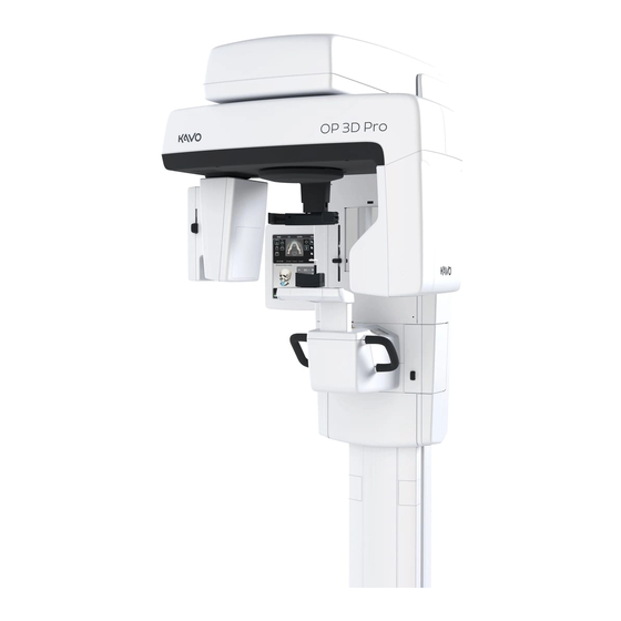
1 Introduction Introduction 1.1 ORTHOPANTOMOGRAPH™ OP 3D Pro ORTHOPANTOMOGRAPH™ OP 3D Pro is a dental X-ray system for producing high quality digital images of dentition, TM-joints and skull. In order to take images with OP 3D Pro you need a suitable PC hardware connected to the OP 3D Pro unit and CLINIVIEW™... -
Page 10: Intended Use
3D Medium panel, H x W (optional) • 50 x 50 mm Field of View • 61 x 78 mm Field of View • 78 x 78 mm Field of View • 78 x 150 mm Field of View • 130 x 150 mm Field of View (optional) NOTICE! The FOV heights are maximum values measured at the center of the FOV, the measured heights at the... -
Page 11: Abbreviations Used In This Manual
1 Introduction • Calibration instructions • Cephalostat upgrade instructions • Cephalostat side changing instructions 1.5 Abbreviations used in this manual FOV = Field Of View. The cylindrical 3D volume that is reconstructed by the system. ROI = Region Of Interest. The anatomical area or region of the patient that you are interested to examine. -
Page 12: Warnings And Precautions
1 Introduction 1.6 Warnings and precautions 1.6.1 Warnings for cross infection Always use available disposable protective covers with the patient positioning accessories: • Bite fork cover • Chin support cover • Head support cover • Nose support cover • Ear holder cover 1.6.2 Warnings to be observed during installation and service... - Page 13 1 Introduction If you have to leave the unit unattended with covers re- moved during servicing or maintenance, disconnect the unit from main power supply so that anyone who inadvertantly touches the unit does not receive an electric shock. This unit should only be used in areas that are provided with a protective earth connection to ensure an equipotential ground connection.
-
Page 14: Cautions For Electrostatic Discharge
1 Introduction 1.6.3 Cautions for Electrostatic discharge Electrostatic Discharge (ESD) can damage or destroy elec- tronic components. When servicing the device take precautions to avoid elec- trostatic build up and discharge (ESD). Follow the recom- mendations for the prevention of ESD that are used in the country in which you are working. - Page 15 1 Introduction Always ensure to fulfill the requirements of the local and na- tional regulations. The correct software and settings in the workstation are essential to the performance of the unit. Consult technical support to ensure correct setup. Danger - Explosion hazard Do not use in the presence of flammable anesthetics, gases or vapors.
- Page 16 1 Introduction When taking exposures, operators and service personnel must protect themselves from radiation and remain at least two meters (six feet) away from the unit during exposure. Protect the patient from scattered radiation by placing a protective lead apron over the patient. The unit must be installed and serviced according to the unit Installation &...
-
Page 17: Disclaimer
1 Introduction If this device is used with 3rd party imaging application software not supplied by the manufacturer, the 3rd party imaging application software must comply with all local laws on patient information software. This includes the Medical Device Directive 93/42/EEC and/or relevant legal requirements in the USA. - Page 18 1 Introduction...
-
Page 19: Unit Description
2 Unit description Unit description 2.1 Main parts and controls 1. Column 2. Carriage 3. Main support 4. Rotating unit 5. On/off switch (rear of carriage) and main fuses 6. Tubehead assembly 7. Touch screen display 8. Patient positioning panel 9. - Page 20 2 Unit description 1. Sensor holder (panoramic units without 3D option) 2. Panoramic sensor 1. 3D sensor (units with 3D option) 2. Panoramic sensor...
-
Page 21: Patient Positioning Lights
2 Unit description 2.2 Patient positioning lights 1. Midsagittal light 2. Frankfort horizontal (FH) light / Horizontal light, top of 130 mm high FOV (Medium Panel 3D option only) 3. Image layer light 4. Cephalometric FH light 5. TMJ light 6. - Page 22 2 Unit description Panoramic lights 1. Midsagittal light 2. FH light 1. Image layer 2. TMJ light...
- Page 23 2 Unit description Cephalometric lights (optional) 1. FH light 3D lights (optional) NOTICE! Appropriate lights are turned automatically on based on selected FOV. 1. Midsagittal light 2. Horizontal light, top of FOV NOTICE! With Medium Panel 3D option, Optional 130 mm height is indicated with Frankfort horizontal (FH) light.
- Page 24 2 Unit description 2.3 Patient positioning panel 1. Carriage UP 2. Carriage DOWN 3. Positioning lights ON/OFF 4. Patient positioning 5. Start position 6. Chin support UP 7. Chin support DOWN 8. Move the image layer anterior before exposure 3 mm, with sinus program 10 mm 9.
-
Page 25: Patient Positioning Panel
2 Unit description 2.4 Main control panel 1. Modality / imaging program section 2. Status of the unit 3. Settings 4. End examination 5. Automatic Dose Control 6. Manual mode 7. Test mode 8. Patient size selection 9. Exposure settings... -
Page 26: Unit Identification Labels
2 Unit description 2.5 Unit identification labels 1. Main label 2. 10A & 15A Fuse labels (next to the fuse holder) 3. Laser class 1 warning label IEC 60825-1:2007 4. Ethernet label 5. Sensors 6. (Primary) collimator label 7. (Secondary) cephalostat collimator label 8. -
Page 27: Unit Movements
2 Unit description 2.6 Unit movements Panoramic unit movements... -
Page 28: Emergency Stop Switch
2 Unit description Cephalometric unit movements 2.7 Emergency stop switch In case of malfunction of the exposure button or other protective devices of the unit, an emergency stop switches are located near the handles and on the cephalostat unit, so that the patient can easily reach them. If the emergency stop switch is pressed during an exposure, the exposure is terminated immediately and the x-ray unit is completely stopped. - Page 29 2 Unit description...
- Page 30 2 Unit description...
-
Page 31: Pre-Installation Requirements
Pre-installation requirements 3.1 The unit ■ See chapter 9 OP 3D Pro Pre-sales check list. ■ The unit is supplied: OP 3D Pro COLUMN MAIN SUPPORT CEPHALOSTAT Packages (card board) AND ROTATION (card board) UNIT (card board) Size (LxWxH) cm: 171 x 65 x 97 cm 118 x 65 x 97 cm 140 x 78 x 88 cm... - Page 32 3 Pre-installation requirements ■ Make sure that the fixing hardware and wall can withstand pull-out strengths of at least 5000 N. NOTICE! Mounting bolts for floor and wall fastening are not included in the delivery. The fixing hardware used to permanently attach the unit to the wall must be correct type for the wall and wall material.
-
Page 33: Space Requirements
3 Pre-installation requirements 3.2 Space requirements When installing the unit make sure that: there is enough space at the front and sides of the unit to allow patients to enter and exit the unit eas- ily. Patients in wheelchairs will require more space than standing patients. -
Page 34: Fixing Hardware And Installation And Setup Tools
3 Pre-installation requirements 3.3 Fixing hardware and Installation and Setup tools The following tools and hardware are required to install and set up the unit. These are not included in the delivery of the unit, unless otherwise stated. Fixing hardware NOTICE! Mounting bolts for floor and wall fastening are not included in the delivery. -
Page 35: Pc Requirements
PC requirements 4.1 Minimum PC requirements Minimum PC requirements for 2D and 3D acquisition workstation Processor Intel Core i5, i7 or Xeon, 4-cores or more GPU (graphics NVIDIA Quadro M2000 4GB or GeForce GTX 1050 Ti processing unit) Memory 8 Gigabytes RAM, or more Hard disk 1 TB or more RAID 1 or RAID 5 recommended for data redundancy,... - Page 36 4 PC requirements Minimum PC requirements for 2D/3D Viewing workstation * Processor 2.0 GHz dual core, or better Memory 3 Gigabytes RAM, or more Graphics card 1GB or more memory (integrated graphics are not supported) Hard disk 3 GB free space, or more Network Gigabit Ethernet 1000Base-T (recommended) or Fast Ethernet...
-
Page 37: The Dental Imaging Software
4 PC requirements Do not position the PC where it could be splashed with liquids. Clean the PC in accordance with the manufacturer’s instructions. The PC to be used with the unit must be installed in a location that meets all local and national safety requirements with regards the connection of a PC to an x-ray device. - Page 38 4 PC requirements...
-
Page 39: Installing The Unit
Installing the unit NOTICE! Save the packaging materials as they may be needed if you move the unit to a new location. 5.1 Content of delivery CEPHALOSTAT BOX COLUMN BOX CARRIAGE BOX (optional) ■ ■ ■ Column Main support Cephalostat arm ■... - Page 40 5 Installing the unit Remove the plastic wrap. Remove the accessory boxes and the main support cover. Fold down the bottom end of the box and slide the unit over the edge of the pallet. Attach the wall bracket(s) to wall. The upper bracket is mandatory.
- Page 41 5 Installing the unit (206908) is required (ordered separately). At least one wall mount bracket is needed for all installations. Erect the column by lifting from the top. Move the unit to the place where it is installed and set it beside the wall.
- Page 42 5 Installing the unit 11. Use a spirit level to ensure the column is plumb in both directions. 12. Remove the plastic wrap from top of the column. Re- move the side covers by removing two bottom screws and loosening two top screws from the cabin.
- Page 43 5 Installing the unit 13. The default maximum height of the unit is 2410 mm. If the room height is less, the column maximum height must be adjusted. The height is adjustable from 2410 mm to 2110 mm by 60 mm steps. Adjust by changing the position of the micro-switch.
- Page 44 5 Installing the unit C. Open 2 screws holding the micro-switches “UP- LIMIT” and “HEIGHT-DET”. Move the micro-switches to appropriate position. Microswitches “UP-LIMIT” and “HEIGHT-DET” are attached with the same screws. Microswitch UP-LIMIT is inside the cable guide.
-
Page 45: The Carriage
5 Installing the unit 5.3 The carriage Transport the carriage box (number 1) to the location where the unit is to be installed. Remove the straps that hold the box to the pallet. Lift off the top of the box and then the sides. Remove the plastic wrap. - Page 46 5 Installing the unit Fold down the edges of the box. Fold the side parts of the styrofoam away, so that the end of the main support, that connects to the column, is fully accessible. Lift the carriage and push it towards the column. The lifting places are shown by arrows in the picture.
- Page 47 5 Installing the unit NOTICE! Do not put the carriage down on the chin rest or on the patient handles! NOTICE! Caution marking located near the Z-lift motor, indicates, that it contains a mechanical protective de- vice. If the mechanical protective device is activated the part shall be replaced by service personnel.
- Page 48 5 Installing the unit Fasten the main support to the column counterpart with 4 screws (M10 x 20mm). Remove the styrofoam material. 10. Remove the transport supports on the main support: 1) thread bars (4 pcs) 2) the sheet of plywood 3) the overhead shipping brackets (3 pcs) and screws.
- Page 49 5 Installing the unit 11. Remove the plastic wrap around the sensor. NOTICE! The plywood may scratch the chin support. Remove carefully!
-
Page 50: Check Leveling
5 Installing the unit 5.4 Check leveling Ensure the unit is level by adjusting the wall bracket(s). The wall bracket allows for the unit to be adjusted all directions. Before adjusting the tubehead must be turned to front position. Use the precision spirit levels on the top of the main support. -
Page 51: Installing Additional Set Screws And Connecting Cables
5 Installing the unit 5.5 Installing additional set screws and connecting cables Locate 2pcs M6X20 DIN913 set screws from the screw bag. Screws are installed both sides of the unit, close to column and upper shelf joint. Use 3mm hex driver/key to install the set screws on both sides. - Page 52 5 Installing the unit Attach the cables on both sides and top of the column. On the left side 1 Gigabit ethernet (marked with “Gigabit”) 2 Grounding point 3 Switch power cable 4 Mains power cable On the right side On the top On the top 1 Connector JB006...
-
Page 53: Attaching The Touch Screen Display To The Column (New Model)
5 Installing the unit 5.6 Attaching the touch screen display to the column (new model) Unfasten the touch screen display arm (1 screw) from vertical position and re-fasten it to the horizontal posi- tion. One screw is pre-installed. Fasten the touch screen display to the arm by 2 screws. Connect the cables (Ethernet, PC power, the grounding cable). - Page 54 5 Installing the unit Fasten the covers.
-
Page 55: Exposure Button
5 Installing the unit 5.7 Exposure button NOTICE! Exposure button is factory installed with a flexible spiral cable. The following installation is done only if other exposure button (optional) is needed. Attach the exposure switch holder to the rear of the touch screen display arm. -
Page 56: External Warning Light (Optional)
5 Installing the unit 5.8 External warning light (optional) NOTICE! External max. 230V warning light can be connected only by doing internal modifications. Only authorized technician is allowed to do this. NOTICE! These instructions are intended only for the remote exposure button assembly (207502). NOTICE! 12V voltage is supplied from the unit for the external warning light. -
Page 57: Installing The Cephalometric Unit
5 Installing the unit 5.9 Installing the cephalometric unit NOTICE! Save the packaging materials as they may be needed if you move the unit to a new location. NOTICE! Check the orientation of the nasion support and the ear holders so that the patient is always facing to the x- ray room. - Page 58 5 Installing the unit Cephalostat upgrade kit: Remove the accessory box. The accessory box con- tains all the bolts required in the cephalostat unit instal- lation. Lift the upmost packaging styrofoam aside.
- Page 59 5 Installing the unit To pull the cephalostat head from the box, grab the low- er packaging styrofoam cells from both sides. Lift the front end slightly and pull the unit out of the box careful- ly, leaving the cephalostat arm to its place. NOTICE! Do not pull from the upper packaging cell to avoid causing any stress to the cephalostat head.
- Page 60 5 Installing the unit CEPHALOSTAT UPGRADE KIT: Attach the four cephalostat arm installation bolts to the back of the column. Take the cephalostat arm from the box and lift it so that the installation bolts go through the four holes of the cephalostat arm.
- Page 61 5 Installing the unit Attach and tighten the cephalostat arm to its place evenly with four nuts. NOTICE! If the cephalostat arm does not fit to its posi- tion, loosen all four nuts and also two screws to fit the arm properly.
- Page 62 5 Installing the unit 11. Remove the upper cover (A) from the cephalostat head and put it aside. Take the cephalostat head out of the styrofoam packaging and lift it carefully to the hook on the other end of the cephalostat arm. 12.
- Page 63 5 Installing the unit Side horizontal adjustment (slightly hanging) Adjust. Loosen the screws. 1) Loosen three nuts. 2) Lift the cephalostat head at the same time, when ad justing with the allen key, until the spirit level is levelled. 3) Use wrench to re-tighten the alignment screw first, and then the two big nuts.
- Page 64 5 Installing the unit Front horizontal adjustment (tilted sideways) 1) Use wrench to loosen the two nuts, then adjust by turning the cephalostat head, until the spirit level is lev- elled. 2) Re-tighten the nuts.
- Page 65 5 Installing the unit Horizontal adjustment (rotated on horizontal level) NOTICE! This adjustment is done only, if the calibration does not pass and the ceph head needs to be rotated. See chapter 7.2.4.4, Cephalostat fixation angle adjust- ment. 14. Attach the cables of the cephalostat arm as shown. On the cephalometric head: 1: Signal/Power cable 2: Ethernet cable...
- Page 66 5 Installing the unit 15. Before installing the upper cover, take a cephalostat calibration image according to the cephalostat calibra- tion instructions in this manual. 16. Install the covers (5 pieces). A Joint cover between cephalostat head and arm B Upper cover of the cephalostat head C Cephalostat arm end cover (for head end) D Top cover of the column E Cephalostat arm end cover (for column end)
- Page 67 5 Installing the unit Top cover of the column.
-
Page 68: Enabling Carpus Imaging
5 Installing the unit 17. Take the sensor out of its package and attach to the sensor holder. Make sure the sensor is properly seated down before pulling the lever. 18. Pull the lever down to lock the sensor to its place. 5.9.1 Enabling carpus imaging Type in s2terminal in service mode: “carpus enable”. -
Page 69: Panoramic And 3D Calibrations And Adjustments
Panoramic and 3D calibrations and adjustments 6.1 Introduction The calibration procedure helps to maintain image quality and correct operation of the unit. When carrying out the full or partial calibration procedure, the calibration and check steps must be carried out in the order in which they are listed. -
Page 70: When To Calibrate The Unit
6 Panoramic and 3D calibrations and adjustments performed as a support for the installer. All calibrations must be done until the system informs they have passed. The exclamation marks disappear when a passed calibration has been saved. NOTICE! After calibrations place all the needed patient positioning accessories back to the chin rest. -
Page 71: Reset Maintenance Counter
6 Panoramic and 3D calibrations and adjustments 3D Panel After replacing the 3D panel redo all the 3D calibrations and the 3D quality check. If the collimator is moved redo all collimator, pixel and geometry calibrations as well as the quality checks. - Page 72 6 Panoramic and 3D calibrations and adjustments d) Key in s2terminal and then the IP address of the unit. Press Settings on the Touch screen display. The IP ad- dress of the unit is shown in the settings window. _______________________________________ s2terminal 10.208.6.101 _______________________________________ e) Press ENTER to open the s2terminal and...
- Page 73 6 Panoramic and 3D calibrations and adjustments 7. Select the Quality Assurance button. The calibration display appears.
-
Page 74: The Calibration Sequence
6 Panoramic and 3D calibrations and adjustments 6.5 The calibration sequence 6.5.1 Calibration of the preheat of the tube NOTICE! Calibration of the preheat of the tube takes a while. The audible signal starts and stops several times. Do this calibration if there has been long time between installation and final testing of the unit or if the other calibrations won’t pass. -
Page 75: Collimator Calibration
6 Panoramic and 3D calibrations and adjustments 6.5.3 3D collimator calibration NOTICE! Only needed with 3D units. 1. Select the 3D Col program. 2. Press Patient Positioning. 3. Take an exposure. NOTICE! Adjust the height and tilt of the collimator manually. - Page 76 6 Panoramic and 3D calibrations and adjustments Clockwise (cw) = Collimator upwards Counterclockwise (ccw) = Collimator downwards 3. Re-tighten the two locking nuts and take a new image.
-
Page 77: Beam Size Verification (Optional)
6 Panoramic and 3D calibrations and adjustments 6.5.4 3D Beam size verification (optional) This program can be used to verify that the size of the 3D X-ray beam does not exceed limits defined in IEC 60601-1- 3 and DIN 6868-161, if required by local regulations. The result of the program only gives information and does not affect the calibration of the unit. -
Page 78: Panoramic Collimator Calibration
6 Panoramic and 3D calibrations and adjustments First two lines are for DIN and the rest for the IEC standard. Field of useful beam (h x w): 126.0 x 129.2 mm result according to DIN. Field of useful beam max. (h x w): 138.7 x 140.3 mm DIN limit. X-ray field (h x w): 126.7 x 131.0 mm result according to IEC. - Page 79 6 Panoramic and 3D calibrations and adjustments 6.5.5.1 Adjustment of the height of the PAN sensor NOTICE! This adjustment is only available on 3D devices. Do the adjustment with the sensor holder. 1. Remove the sensor. 2. Remove the sensor holder cover by removing four M4 screws.
- Page 80 6 Panoramic and 3D calibrations and adjustments 3. Loosen five screws of the sensor holder. 4. Adjust the height with an adjustment screw on the bottom of the holder. Clockwise (cw) = Collimator upwards Counterclockwise (ccw) = Collimator downwards 6.5.5.2 Horizontal adjustment of the collimator "BLD-NGEO-S-2"...
- Page 81 6 Panoramic and 3D calibrations and adjustments 2. Open the nut when adjusting the Allen screw. Hold the nut when adjusting the Allen screw. 3. Re-tighten the nut after Allen screw is adjusted. Take a new image. NOTICE! 3D collimator calibration should be checked if the collimator is moved horizontally.
-
Page 82: Panoramic Geometry Calibration
6 Panoramic and 3D calibrations and adjustments 6.5.6 Panoramic geometry calibration 1. Select the Pan Geom program. 2. Press Patient Positioning. 3. Install the chin rest and double cone calibration tool. Chin rest and double cone calibration tool. 4. Take an exposure. 5. -
Page 83: Geometry Calibration
6 Panoramic and 3D calibrations and adjustments 6.5.7 3D geometry calibration 1. Attach the adjustable phantom holder to the lower shelf. Level it with the bubble on the adjustable phantom hold- 2. Install the 3D calibration phantom. Check that the phantom is level by using a spirit level. -
Page 84: Sfov (Small Panel) 3D Lasers Alignment
6 Panoramic and 3D calibrations and adjustments 6.5.8 SFOV (Small panel) 3D lasers alignment NOTICE! With MFOV unit (Medium panel) see the instructions in chapter 6.5.9. Remove the mirror plate by loosening four M4 screws. Lift the plate first and pull. 1. - Page 85 6 Panoramic and 3D calibrations and adjustments 5. Loosen the two screws (A) of the bottom laser. Align the height of the laser by moving it up or down. 6. Loosen the screw (B) of the upper laser. Align the tilt of the laser by rotating it.
-
Page 86: Mfov (Medium Panel) 3D Lasers Alignment
6 Panoramic and 3D calibrations and adjustments 7. Loosen the two screws (C) of the bottom laser. Align the tilt of the laser by rotating. 8. Briefly press the exposure button (no X-rays are generat- ed) to acknowledge that the check has been carried out. 6.5.9 MFOV (Medium panel) 3D lasers alignment... - Page 87 6 Panoramic and 3D calibrations and adjustments 2. Select the 3D lasers program. 3. Press Patient Positioning. NOTICE! Lasers can be turned on by pushing the light button. Lasers stay on approx. 30 seconds. 4. Align the 3D lasers of MFOV (Maxio) by using the MFOV 3D lasers alignment tool (L-shaped metal plate).
- Page 88 6 Panoramic and 3D calibrations and adjustments 1 FH-laser of FOV 130 x 150 mm 2 Top of FOV 78 mm 3 Top of FOV 61 mm 4 Top of FOV 50 mm 5 Bottom of FOV 6 MFOV3D lasers alignment tool 7 3D geometry calibration phantom 6.
- Page 89 6 Panoramic and 3D calibrations and adjustments 7. Adjust the lowest laser vertically. Loosen the two screws. Move the plate vertically. Tighten the screws. 8. Adjust the three upper lasers from bottom to up. Loosen the screw next to the laser. Align the laser first horizon- tally and then vertically.
-
Page 90: Panoramic Laser Alignment
6 Panoramic and 3D calibrations and adjustments 9. Adjust the FH-laser used for 130 x 150 FOV to the corre- sponding grooves by mechanically adjusting the lasers. 10.Briefly press the exposure button (no X-rays are gener- ated) to acknowledge that the check has been carried out. - Page 91 6 Panoramic and 3D calibrations and adjustments 3. Press Patient Positioning. 4. Remove the lower shelf bottom cover. 5. Align the layer laser, FH-laser and mid-sagittal lasers to the corresponding grooves by mechanically adjusting the lasers. The layer laser is adjusted by the screws below the chin rest.
-
Page 92: Pixel Calibration
6 Panoramic and 3D calibrations and adjustments NOTICE! Lasers can be turned on by pushing the light button. Lasers stay on approx. 30 seconds. 6. Briefly press the exposure button (no X-rays are generat- ed) to acknowledge the adjustment has been carried out. The rotation and Y-position are also saved. -
Page 93: Quality Check
6 Panoramic and 3D calibrations and adjustments NOTICE! Re-do panoramic pixel calibration, if cephalostat sensor is moved to panoramic side or the sensor is changed. 1. Attach the tube head covers. 2. Remove the calibration tools. 3. Select the Pan Pix program. 4. - Page 94 6 Panoramic and 3D calibrations and adjustments The results of the periodical checks below should be recorded and the check images filed. To do this, it is recommended that a “Constancy Test” “Patient” record is created under which the test images can be recorded. Please note that the reference levels may change with x- ray unit firmware / driver updates.
- Page 95 6 Panoramic and 3D calibrations and adjustments To check results, open resulting image in a 3D viewer. One axial slice of the volume contains Pass/Fail status and one axial slice measurement results and used reference values. If “Passed” is not achieved, redo the 3D collimator, 3D pixel and 3D geometry calibrations before retrying 3D Pass/Fail calculation is based on ROI (Region of Interest) measurement result verification against reference values.
- Page 96 6 Panoramic and 3D calibrations and adjustments “ROIs” smaller volumes inside reconstructed volume that are used to calculate noise or average grey values, for example. ROIs are marked with thin circular lines inside the reconstructed volume. Last lines of text on the image tell the file name of the measurement results stored in a csv table.
- Page 97 6 Panoramic and 3D calibrations and adjustments Artefacts This check is carried out visually. Person with experience on interpreting 3D images should perform the check. Examine the axial slices of 3D QC volume taken in the previous QC steps. Be aware of artefacts which do not originate from the object or from the projection conditions.
-
Page 98: Panoramic Quality Check (Optional)
6 Panoramic and 3D calibrations and adjustments Not acceptable; discontinuity in circular shape due to geometry mismatch between scans with different offset. In similar artefacts are observed, redo 3D geometry calibrations before retrying 3D QC. 6.5.14 Panoramic Quality Check (optional) 1. - Page 99 6 Panoramic and 3D calibrations and adjustments 2. Select the Pan QC program. 3. Press Patient Positioning. 4. Take an exposure.
- Page 100 6 Panoramic and 3D calibrations and adjustments 5. Visually evaluate the result using the installed imaging software. Subjects to be evaluated: 1. Smoothness of the exposed area. Non-exposed area surrounds the whole image. 2. High contrast resolution; minimum 3.1LP/mm must be distinguishable.
-
Page 101: Cephalometric Calibration And Alignment
7 Cephalometric calibration and alignment Cephalometric calibration and alignment 7.1 Preparations NOTICE! The nasion support and the ear holders must be turned out of the way for cephalostat calibrations, so they are not in front of the x-ray beam. NOTICE! Check the orientation of the nasion support and the ear holders so that the patient is always facing to the x- ray room. -
Page 102: Balancing The Cephalostat
7 Cephalometric calibration and alignment These steps are described in more detail in the following sections. The adjustments are to be carried out in the described order. 7.2.1 Balancing the cephalostat See chapter 5.9 Installing the cephalometric unit, step 9. 7.2.2 Primary collimator calibration 1. -
Page 103: Rotation Angle Calibration
7 Cephalometric calibration and alignment 7.2.3 Rotation angle calibration 1. Attach the cephalostat sensor to cephalostat sensor holder. 2. Select CEPH Rotate Angle calibration. 3. Press Patient Positioning. 4. Take an exposure. 5. Check that the calibration is “passed”. If it is not, redo the calibration. - Page 104 7 Cephalometric calibration and alignment...
-
Page 105: Mechanical Adjustment Program
7 Cephalometric calibration and alignment 7.2.4 Mechanical adjustment program Mechanical adjustments of primary and secondary collimator, as well as adjustment of the cephalostat fixation angle, are guided by a mechanical adjustment program. This program gives an image with three exposed areas of interest (marked with arrows in the figure). - Page 106 7 Cephalometric calibration and alignment To complete this calibration: 1. Select the CEPH Mech Adj program. 2. Press Patient Positioning. 3. Take an exposure. 4. Follow the instructions in the calibration result image. Possible instructions and references to further informa- tion are found in table “instructions for adjustment”.
- Page 107 7 Cephalometric calibration and alignment Table 8.1 Instructions for adjustment Instruction Additional information Move primary collimator UP/DOWN. The vertical position of the primary collimator must be adjusted in order to have the X-ray beam aligned to correct height. See chapter 8.2.4. Primary collimator vertical adjustment for details.
- Page 108 7 Cephalometric calibration and alignment Table 8.1 Instructions for adjustment Instruction Additional information Turn cephalostat head CW/CCW and redo Ceph Rot an- The fixation angle of the cephalostat gle calibration. must be adjusted in order to have the secondary collimator and sensor aligned with the X-ray source.
- Page 109 7 Cephalometric calibration and alignment 7.2.4.1 Primary collimator "BLD-NGEO-S" vertical adjustment 1. Loosen the two locking nuts (black circles in the picture). 2. Adjust the vertical position of the collimator using the ad- justment screw (a white circle in the picture). 3.
- Page 110 7 Cephalometric calibration and alignment 3. Tighten the locking nut. 7.2.4.3 Primary collimator "BLD-NGEO-M" vertical adjustment 1. Loosen the locking nut. 2. Adjust the vertical position of the collimator using the ad- justment nut. Clockwise (cw) = Collimator upwards Counterclockwise (ccw) = Collimator downwards.
- Page 111 7 Cephalometric calibration and alignment 3. Tighten the locking nut.
- Page 112 7 Cephalometric calibration and alignment 7.2.4.4 Cephalostat fixation angle adjustment 1. Loosen two locking screws located in the bottom of the cephalostat, next to the cephalostat arm. 2. Slightly loosen two more locking screws, located next to the cephalostat arm. 3.
- Page 113 7 Cephalometric calibration and alignment 7.2.4.5 Removing secondary collimator covers 1. Loosen the counter piece screws (2 pcs) through the holes in the cover. 2. Lift the cover to have it removed. 3. Remove the two lower screws and loosen the two upper screws (marked with arrows in the picture) to remove the second cover.
- Page 114 7 Cephalometric calibration and alignment 7.2.4.6 Secondary collimator vertical adjustment 1. Loosen four locking screws. Collimator vertical locking screws. 2. Adjust the vertical position of the lead plates using the adjustment screw. Vertical adjustment screw. 3. Tighten the locking screws.
- Page 115 7 Cephalometric calibration and alignment 7.2.4.7 Secondary collimator tilt adjustment 1. Loosen two locking screws. 2. Adjust the tilt of the secondary collimator using the tilt ad- justment screw. 3. Tighten the locking screws.
-
Page 116: Secondary Collimator Horizontal Adjustment
7 Cephalometric calibration and alignment 7.2.5 Secondary collimator horizontal adjustment 1. Select Secondary Collimator Horizontal adjustment. 2. Press Patient Positioning. 3. Take an exposure. 4. Repeat the calibration until calibration result “passed” is achieved. - Page 117 7 Cephalometric calibration and alignment...
-
Page 118: Cephalostat Laser Alignment
7 Cephalometric calibration and alignment 7.2.6 Cephalostat laser alignment 1. Select the CEPH Lasers program. 2. Press Patient Positioning. 3. Check that the laser beam is horizontal and that it goes through the center of the ear rod. 4. If the laser needs to be adjusted, loosen the screws of the laser shown on image and tighten it to its place when the laser is horizontal. -
Page 119: Cephalostat Pixel Calibration
7 Cephalometric calibration and alignment 5. When the adjustments are done press the exposure but- ton (no X-rays are generated) to acknowledge that the check has been carried out. 7.2.7 Cephalostat pixel calibration 1. Attach secondary collimator and tubehead covers. 2. - Page 120 7 Cephalometric calibration and alignment 2. Select the CEPH QC program. 3. Press Patient Positioning. 4. Take an exposure.
-
Page 121: Ear Holder Alignment
7 Cephalometric calibration and alignment 5. Visually evaluate the result using the installed imaging software. Subjects to be evaluated: 1. Smoothness of the exposed area. Non-exposed area surrounds the whole image. 2. High contrast resolution; minimum 3.1LP/mm must be distinguishable. 3. - Page 122 7 Cephalometric calibration and alignment 3. Take an exposure. 4. Both ear holders have a small metal ball that should be visible in the image: both balls should be displayed in the same point so that they merge into a single ball. The larg- er ball represents the tube side, and the smaller ball the cephalostat sensor side.
-
Page 123: Horizontal Adjustment
7 Cephalometric calibration and alignment 7.2.10 Horizontal adjustment Rotate the ear holder assembly to access to all locking screws. 1. Loosen the 4 locking screws (A) on the ear holder as- sembly. To ease the loosening, lock the ear holder assembly to its place with the Top view of ear holder assembly. -
Page 124: Vertical Adjustment
7 Cephalometric calibration and alignment 7.2.11 Vertical adjustment 1. Loosen the 4 locking screws (B) on the ear holder as- sembly. Top view of ear holder assembly. Vertical adjustment screw Locking screw (B) 2. Mark the starting position to the scale beside the screw. 3. -
Page 125: Special Procedures
When updating the unit, e.g. with a cephalometric or 3D option, it is always recommended to update the unit with latest firmware and the image capturing PC with the latest driver software (KaVo Driver Update CD). Please contact manufacturer’s Technical... - Page 126 8 Special procedures Remove the top cover of the column. Remove the cables that go from the cephalostat head to the cephalostat arm. The cables can be left inside the arm.
- Page 127 8 Special procedures Loosen two screws, lift the cephalostat head and re- move it from the arm. Remove the cables that go from the arm to the column. On top of the unit column: 1: Signal/Power cable 2: Ethernet cable 3: Grounding point NOTICE! There should be jumper JB006 connected to the connector JB006, when cephalometric unit is NOT...
- Page 128 8 Special procedures Remove the arm from the column (4 nuts). Disassemble the arm.
- Page 129 8 Special procedures Right handed cephalostat arm. Rotate the arm 180° with the cable inside. Re-assem- ble the arm from left handed to right handed (or vice versa when needed). Left handed cephalostat arm.
- Page 130 8 Special procedures Notice the side of the square apertures in both arm ends. Re-attach the cables from the column to the arm. 1: Signal/Power cable, 2: Ethernet cable, 3: Grounding point 10. Rotate the cephalostat head. Move the fastening plate of the cables to the other side of the cephalostat head.
- Page 131 8 Special procedures 11. Move the bubble level to the other side of the cepha- lostat head. (right handed assembly) 12. Re-route the cables from the sensor to the other side of the cephalostat head. (right handed assembly) 13. Move the prism assembly to the other side of the ceph- alostat head.
- Page 132 8 Special procedures (right handed assembly) Prism assembly for the left handed cephalostat.
- Page 133 8 Special procedures Prism assembly for the right handed cephalostat. 14. Move the 2 stop screws (A) to the other side so that when the patient is in the unit, they will be facing for- wards to the room. 15. Re-attach the cephalostat head to the arm.
-
Page 134: Changing The Cephalostat Arm Side In Service Mode
8 Special procedures 16. Re-connect the cables from the arm to the cephalostat head. 17. Re-attach the unit covers. 8.4 Changing the cephalostat arm side in service mode Usage: unithandedness [main|ceph|all] [l|r] main: Sets handedness for main unit ceph: Sets handedness for cephalostat unit all: Sets handedness for both cephalostat and main units l: The GUI and/or cephalostat are on the left side of the unit... -
Page 135: Adjusting And Calibrating The Cephalostat
8 Special procedures r: The GUI and/or cephalostat are on the right side of the unit Use this to define the handedness options of the unit. Usage examples: unithandedness ceph l => cephalostat is on the left side of the unit unithandedness main r =>... -
Page 136: Connecting The Unit To The Mains
8 Special procedures 8.6 Connecting the unit to the mains WARNING! Only an authorized technician is allowed to perform the mains voltage change of the unit. WARNING! Do not connect the unit to the mains voltage until instructed to do so. NOTICE! Units are delivered from the factory with 230Vac line voltage settings. - Page 137 8 Special procedures Remove the cover (A) under the lower shelf. Remove the metal plate by loosening 4 screws. On the EA200 board there is a jumper (J1) for line volt- age selection. If you have 220-240Vac mains voltage, you should install jumper marked with 230Vac to the J1 position.
- Page 138 8 Special procedures ■ For 220-240Vac use two 10A fuses, type T10A H 250V (Littelfuse 326 010) ■ For 100-120Vac use two 15A fuses, type T15A H 250V (Littelfuse 326 015) Loosen the screws (DO NOT REMOVE) of the mains inlet cover and remove the cover.
-
Page 139: Preparing The Pc
8 Special procedures 8.6.1 Preparing the PC NOTICE! See the Service Manual for instructions on changing the IP address. Position the PC to be used with the unit at least 1.85m (73 in) away from the unit. NOTICE! If the unit and PC are to be part of a dental system make sure that all the other system compo- nents and devices are installed, connected and config- ured correctly. - Page 140 8 Special procedures Connect one end of the Ethernet cable to the unit (the connector at the rear of the column) and the other end to the PC. Switch the unit on and carry out initialization. PC: Start the PC and then open CLINIVIEW™ or the dental imaging software that you installed.
-
Page 141: Firmware Update
8 Special procedures 8.7 Firmware update 8.7.1 Preparing for update You need the following for a typical update: The latest release package, available from Technical Support’s extranet site. A host PC for performing the update. The host PC may be a separate PC (e.g. -
Page 142: Software Update
8 Special procedures An s2terminal connection is established to the unit. A list of command shortcuts (macros) is printed. These may be used to streamline the update process. Alterna- tively, the commands can be typed in manually. 8.7.2 Software update The embedded software release package consist of a number of compatible software components. - Page 143 8 Special procedures 6) Update the R3300 firmware and core. 7) Update the Ceph R3210 core (units equipped with cephalostat). 8) Power off and on again. 9) Update the Ceph firmware (units equipped with cephalostat). 10) Set software release version. After updating any software component, the unit must be restarted before normal operation is resumed.
- Page 144 8 Special procedures GUI software update Press the F4 button and press enter, or type in manually: xcc gui R<ver_major>.<ver_minor> Example: xcc gui R2.00 Wait for the software package to be transferred. Make sure that the transfer is successful by following the messages printed in the s2terminal prompt.
- Page 145 8 Special procedures Cephalostat CPU FPGA core update NOTICE! The instructions below are valid when the cephalostat CPU is currently running a previous version of the cephalostat software. For instructions on programming a non-responsive or unprogrammed spare part CPU board, refer to chapter Special cases.
-
Page 146: Volatile Installation
8 Special procedures sions.txt included in the software release package. If all versions match, proceed to the next step. Otherwise, you must first update the mismatching components. Set the software release version by pressing F9, or by manually typing: pmode 0 <ver_major> <ver_minor> Example: pmode 0 2 00 The unit should reply... -
Page 147: Installation Procedure
8 Special procedures https://www.altera.com/download/software/prog-software The jic/sof programming file for the circuit board to be programmed, included in the software update package. 8.8.1 Installation procedure 8.8.1.1 R3210, R3300, R3400 Connect the USB-Blaster's USB connector to a PC with the Quartus II Programmer software installed. Connect the USB-Blaster's 10-pin connector to the JTAG port on the circuit board to be programmed (see circuit board specific connections below). - Page 148 8 Special procedures ware drop down list and click Close. Click the Auto Detect button to have the programmer detect the device type and verify the connection to the circuit board. Select the first row in the list and click the Change File…...
- Page 149 8 Special procedures entation of the connector! Start Quartus II programmer and click the Hardware Setup button in the upper left corner. Select USB-Blaster from the Currently selected hard- ware drop down list and click Close. Click the Auto Detect button and select 5CEFA5 de- vice.
-
Page 150: Special Cases
8 Special procedures Mark the Program/Configure check box. Click the Start button and wait for the download to com- plete (takes a few seconds). 10. Volatile installation is typically followed by a permanent install. Refer to chapter Manual update for instructions on how to do this. -
Page 151: Programming A Non-Responsive Cephalostat Cpu
8 Special procedures Power on the unit again. When a connection is estab- lished, type in safe and press enter before the countdown in the boot prompt ends. This puts the unit in safe mode for R3220 firmware update. Update the firmware using the command xfp OP3DPRO_FW_R<ver_major>_<ver_minor>.srec Example: xfp OP3DPRO_FW_R2_00.srec... - Page 152 8 Special procedures Connect an Ethernet cable between the host PC and the 100 Mb/s Ethernet port (J3211) on the cephalostat CPU board. Run the openS2.bat file to have an s2terminal session started. Refer to chapter Preparing for update for more detailed instructions.
- Page 153 8 Special procedures ;Flashing image (263148 bytes) @0x120000 Status command transfer error. Verifying... Error in login reply - command executed verified ok Done. Connected to CBCT CEPH R3200c boot-2.18R2798> Wait for the software package to be transferred and for the cephalostat CPU to boot itself. If the update fails, try again.
- Page 154 8 Special procedures Update the FGPA core using command: r3210 OP3DPRO_CEPHR3210_R<ver_ma- jor>_<ver_minor>.srec Example: CEPH R3200c boot-2.18R2798>xcp r3210 OP3DPRO _CEPHR3210_R2_00.srec OP3DPRO Transferring _CEPHR3210_R2_00.srec to Main CPU Updating core... transfer 864965 bytes from S-records... update 0 864965 = 0x0..+864965 FRAMES:1205 Flashing image (864965 bytes) @0x0 Status command transfer error.
-
Page 155: Troubleshooting
8 Special procedures of the CPU board has changed). Verify that the version of the firmware matches the one listed for "Ceph FW" and "Ceph Core" in the release package's versions.txt file using command: login Example: ngeoceph> login main 1.4.4693/2012-08-10T15:32:43/TUULTESKELINEN core 2012-01-31T12:17:34/EP2C70F672C6/AUTO 10. -
Page 156: Problem: Automatic Software Update Fails
8 Special procedures the host PC notice the change and update its routing tables. 8.10.2 Problem: Automatic software update fails Indication: Failure message from the automatic updater. Possible reasons and solutions: Automatic software update may fail for example due to connectivity problems. Problems may also occur when updating from early embedded software versions. -
Page 157: Configurable Panoramic Mas Limit
8 Special procedures Wrong command syntax or binary file name typed in. Check the syntax and filename. The files are not found in the assumed location. Run the s2terminal using the openS2.bat file found in the soft- ware release package's root folder. Check that the file mentioned in the error message is really present. - Page 158 8 Special procedures...
-
Page 159: Op 3D Pro Pre-Sales Check List
9 OP 3D Pro Pre-sales check list OP 3D Pro Pre-sales check list Dealer Dealer contact person Clinic name Clinic contact person Clinic address Clinic tel. Clinic IT contact Targeted installation date Targeted application training date Signature & Date Sales person End user One copy to sales person and one copy to end user. -
Page 160: Mechanical Specifications
9 OP 3D Pro Pre-sales check list 9.3 Mechanical Specifications Installation space: Pan/3D: Minimum installation space Depth: 1700 mm Width: 1500 mm Height: 2410 mm at minimum (max height adjustable from 2110 to 2410) End User/Dealer Cephalostat: Minimum installation space Depth: 1700 mm Width: 2500 mm Height: 2410 mm at minimum... -
Page 161: Networking Specifications
9 OP 3D Pro Pre-sales check list 9.5 Networking Specifications APPROVAL LEVEL Does Modifi- Com- RESPONSIBILITY not meet cation ment needed specs 1Gb/s network to all The connection between the End User/Dealer components unit must meet volved with OP 3D EN60601-1 requirements. -
Page 162: Computer Specifications
9 OP 3D Pro Pre-sales check list 9.6 Computer Specifications See chapter 4 for PC requirements. 9.7 Backup Specifications CLINI- It is recommended to use a End User VIEW™database suitable backup system that must be backed up can easily be removed for off- with an appropriate site storage. -
Page 163: Software Configuration
9 OP 3D Pro Pre-sales check list 9.9 Software configuration DETAILS ™ Which software CLINIVIEW software (re- components are in- quired) cluded in delivery? OnDemand3D Dental (3D visualization software) ™ CLINIVIEW software DI- NOTE: COM Option If full integration into a DICOM envi- ronment is needed, software DICOM Option is required. -
Page 164: Other Information
9 OP 3D Pro Pre-sales check list 9.10 Other information 3rd party 3D soft- Is CLINIVIEW™ software go- ware: ing to be used with existing 3rd party 3D software? NOTE: Direct link between CLINIVIEW™ and 3rd party 3D software is available for the following software: Materialise Simplant,... -
Page 165: Notes / Comments
9 OP 3D Pro Pre-sales check list 9.11 Notes / comments... -
Page 166: Dimensions
9 OP 3D Pro Pre-sales check list 9.12 Dimensions... -
Page 167: Dimensions With Cephalostat
9 OP 3D Pro Pre-sales check list 9.13 Dimensions with cephalostat... - Page 168 9 OP 3D Pro Pre-sales check list...
Need help?
Do you have a question about the ORTHOPANTOMOGRAPH OP 3D Pro and is the answer not in the manual?
Questions and answers