Table of Contents
Advertisement
Quick Links
Advertisement
Table of Contents

Subscribe to Our Youtube Channel
Related Manuals for KaVo OP 3D Pro


Summary of Contents for KaVo OP 3D Pro
- Page 1 ORTHOPANTOMOGRAPH ™ OP 3D Pro User manual ENGLISH 216364 rev. 6 0.805.5115...
-
Page 3: Table Of Contents
Contents 1 Disclaimer..............6 2 Introduction..............7 ™ 2.1 ORTHOPANTOMOGRAPH OP 3D Pro............7 2.2 Intended use..................8 2.3 Indications for use (USA only)..............8 2.4 Intended user profile................8 2.5 Associated documentation............... 8 2.6 References.....................8 2.7 Abbreviations used in this manual............8 2.8 Signal words.................. - Page 4 9.4.1 3D geometry calibration............. 86 9.4.2 3D pixel calibration..............87 9.4.3 3D Quality Check program............88 9.5 Cephalometric calibration...............89 9.5.1 Ceph pixel calibration..............89 9.5.2 Ceph Quality check program (Optional)........90 10 Technical data............92 10.1 Technical specifications................ 92 ™ ORTHOPANTOMOGRAPH OP 3D Pro...
- Page 5 10.3 Symbols that may appear on the device or its parts......107 10.4 Labels on the unit................109 10.5 Electromagnetic Compatibility (EMC) tables.......... 109 10.6 X-ray tube assemblies............... 113 11 PC requirements............115 11.1 Minimum PC requirements..............115 11.2 The dental imaging software...............116 ™ ORTHOPANTOMOGRAPH OP 3D Pro...
-
Page 6: Disclaimer
1 Disclaimer 1 Disclaimer ™ ORTHOPANTOMOGRAPH OP 3D Pro User manual, 216364 r6. © Copyright 11-2020 by Instrumentarium Dental, PaloDEx Group Oy. All rights reserved. ™ ™ ™ ORTHOPANTOMOGRAPH , CLINIVIEW and ORTHOfocus are either registered trademarks or trademarks of Instrumentarium Dental, PaloDEx Group Oy in the United States and/or other countries. -
Page 7: Introduction
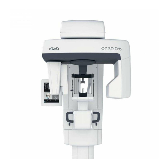
™ The ORTHOPANTOMOGRAPH OP 3D Pro (hereafter called "unit") is a dental X-ray system for producing high quality digital images of dentition, TM-joints and skull. In order to take images with the unit you need a suitable PC hardware connected to the ™... -
Page 8: Intended Use
● The user manual supplied with the 3D imaging software ● The installation manual supplied with the 3D imaging software 2.6 References The following instructions are delivered with in the OP 3D Pro installation manual: ● Firmware update instructions ● Calibration instructions ●... -
Page 9: Signal Words
● Because the x-ray limitations and safety regulations change from time to time, it is the responsibility of the user to make sure that all the valid safety regulations are fulfilled. ™ ORTHOPANTOMOGRAPH OP 3D Pro... -
Page 10: Warnings For Cross Infection
2.10.2 Warnings for cross infection Always use available disposable protective covers with the patient positioning accessories: ● Bite fork cover ● Chin support cover ● Head support cover ● Nose support cover ● Ear rod cover ™ ORTHOPANTOMOGRAPH OP 3D Pro... -
Page 11: General Warnings
3D imaging should not be used for routine or screening examinations in which a radiograph is taken regardless of the presence or absence of clinical signs and symptoms. 3D imaging examinations must be justified for each patient to demonstrate that the benefits outweigh the risks. ™ ORTHOPANTOMOGRAPH OP 3D Pro... - Page 12 - PC connection, or when scanning 2D images without patient ID, that images retrieved from the unit are associated to the correct patient. Correct sharp layer should be chosen when using multilayer PAN images. See user manual chapter Multilayer PAN images for correct procedure. ™ ORTHOPANTOMOGRAPH OP 3D Pro...
-
Page 13: Unit Description
PC with MDD approved dental imaging software and 3D viewing software (not included). All software must conform to the MDD and the relevant legal requirements in the USA. The PC must conform to all the unit and dental imaging software requirements. ™ ORTHOPANTOMOGRAPH OP 3D Pro... -
Page 14: Patient Positioning Lights
5. TMJ light 6. Horizontal light, top of 78 mm high FOV 7. Horizontal light, top of 61 mm high FOV 8. Horizontal light, top of 50 mm FOV 9. Horizontal light, bottom of FOV ™ ORTHOPANTOMOGRAPH OP 3D Pro... - Page 15 3 Unit description Panoramic lights 1. Midsagittal light 2. FH light 1. Image layer light 2. TMJ light Cephalometric lights (optional) 1. FH light ™ ORTHOPANTOMOGRAPH OP 3D Pro...
-
Page 16: Patient Positioning Panel
8. Move the image layer anterior before exposure 3 mm, with sinus program 10 mm 9. Normal occlusion/ reset position 10. Move the image layer posterior before exposure 3 mm, with sinus program 10 mm ™ ORTHOPANTOMOGRAPH OP 3D Pro... -
Page 17: Cephalometric Unit Patient Positioning Panel (Optional)
3 Unit description 3.4 Cephalometric unit patient positioning panel (optional) 1. Carriage UP 2. Carriage DOWN 3. Positioning lights ON/OFF ™ ORTHOPANTOMOGRAPH OP 3D Pro... -
Page 18: Accessories
Lower head support for FOV 130 x 150 mm imaging ● Bite block disposable covers ● Chin support disposable covers ● Temple support disposable covers ● Nasion support disposable covers ● Ear rod disposable covers ™ ORTHOPANTOMOGRAPH OP 3D Pro... -
Page 19: Other Detachable Parts
QC phantom Cone phantom (for panoramic geometry calibration) Panoramic quality check tool (option) Panoramic quality check tool adapter for ceph (option) Sensor (Pan and Ceph) Temple support assembly Lasers alignment tool Platform for dental model ™ ORTHOPANTOMOGRAPH OP 3D Pro... -
Page 20: Emergency Stop Switch
<5 min for ear rod Sinus/Chin rest Skin <5 min Nose support Skin <5 min Disposable cover Skin <5 min for Nose support Temple support Skin <5 min Disposable cover Skin <5 min for Temple support ™ ORTHOPANTOMOGRAPH OP 3D Pro... -
Page 21: Imaging Programs
70 kV/ 12.5 mA/ mGycm mGycm mGycm 123 mGycm 230 VAC 66 kV/ 5 mA/ 44 66 kV/ 8 mA/ 70 66 kV/ 10 mA/ 88 70 kV/ 12.5 mA/ mGycm mGycm mGycm 123 mGycm ™ ORTHOPANTOMOGRAPH OP 3D Pro... - Page 22 The result of this scanning location will allow for views of the TM joint and molar area without redundant shadows from the opposite side ramus obscuring the image. Patients with prosthetic condyles or other posterior radio opaque objects can have the opposite side successfully imaged. ™ ORTHOPANTOMOGRAPH OP 3D Pro...
- Page 23 70 kV/ 12.5 mA/ mGycm mGycm mGycm 97 mGycm 230 VAC 66 kV/ 5 mA/ 35 66 kV/ 8 mA/ 55 66 kV/ 10 mA/ 69 70 kV/ 12.5 mA/ mGycm mGycm mGycm 97 mGycm ™ ORTHOPANTOMOGRAPH OP 3D Pro...
- Page 24 122 mGycm 230 VAC 66 kV/ 5 mA/ 43 66 kV/ 8 mA/ 69 66 kV/ 10 mA/ 87 70 kV/ 12.5 mA/ mGycm mGycm mGycm 122 mGycm Lateral TMJ: Magnification 1.23 ™ ORTHOPANTOMOGRAPH OP 3D Pro...
- Page 25 73 kV/ 16 mA/ 96 mGycm mGycm 76 mGycm mGycm 230 VAC 73 kV/ 6.3mA/ 38 73 kV/ 10 mA/ 61 73 kV/ 12.5 mA/ 73 kV/ 16 mA/ 96 mGycm mGycm 76 mGycm mGycm ™ ORTHOPANTOMOGRAPH OP 3D Pro...
- Page 26 73 kV/ 12.5 mA/ mGycm mGycm 68 mGycm 85 mGycm 230 VAC 66kV/ 6.3mA/ 34 66 kV/ 10 mA/ 54 66 kV/ 12.5 mA/ 73 kV/ 12.5 mA/ mGycm mGycm 68 mGycm 85 mGycm Bitewing: Magnification 1.3 ™ ORTHOPANTOMOGRAPH OP 3D Pro...
-
Page 27: Sectional Imaging
75 mGycm 4.2 Sectional imaging The OP 3D Pro has ability to provide sectional images. Dental arch on the touch panel shows the enabled and disabled arch sections from the result point of view. Select the desired image area from the dental arch. -
Page 28: Panoramic Automatic Dose Control (Adc)
Exposure value ranges used in ADC mode are: ● Voltage: 57 – 90 kV ● Current: 3.2 – 16 mA The signal to noise ratio can be adjusted while keeping ADC engaged. Adjustment is done from the GUI. ™ ORTHOPANTOMOGRAPH OP 3D Pro... -
Page 29: Orthofocus
2. To mark the previewed image to be saved, press the thumbnail again. A Save indication icon appears on the upper right corner of the thumbnail image. 3. Repeat the process for all desired images. ™ ORTHOPANTOMOGRAPH OP 3D Pro... -
Page 30: User Configurable Panoramic Ma Level
1. Start an exam and select the desired program. 2. Press the Settings button on the touch screen. 3. Select Imaging program defaults. 4. Select Set current program as default. 4.8 Cephalometric programs Cephalometric pediatric lateral projection ™ ORTHOPANTOMOGRAPH OP 3D Pro... - Page 31 16 s/72 mGycm 20 s/90 mGycm Cephalometric lateral projection Lateral Cephalostat uses full height image field that provides a nearly full skull image. The starting point of the lateral scan is adjustable. ™ ORTHOPANTOMOGRAPH OP 3D Pro...
- Page 32 90 kV/ 12.5 mA/ s/ 42 mGycm s/ 47 mGycm 16 s/ 76 mGycm 20 s/ 95 mGycm Cephalo posterior-anterior (PA) projection Lateral Cephalostat uses a full sensor image height. Reverse towne projection Waters view ™ ORTHOPANTOMOGRAPH OP 3D Pro...
- Page 33 66 kV/ 3,2 mA/ 8 70 kV/ 3,2 mA/ 8 73 kV/ 3,2 mA/ 8 73 kV/ 6,3 mA/ 8 120 VAC s/ 5 mGycm s/ 5 mGycm s/ 6 mGycm s/ 12 mGycm 230 VAC ™ ORTHOPANTOMOGRAPH OP 3D Pro...
-
Page 34: Programs, Small Panel
Program optimized for endodontic imaging: Endo program (85μm voxel size) 61 x 78 mm FOV Available resolutions: High resolution (200μm voxel size) Standard resolution (300μm voxel size) ™ Low Dose Technology (LDT) resolution (330μm voxel size) ™ ORTHOPANTOMOGRAPH OP 3D Pro... -
Page 35: Programs, Medium Panel
Program optimized for endodontic imaging: Endo program (85μm voxel size) 61 x 78 mm FOV Available resolutions: High resolution (200μm voxel size) Standard resolution (300μm voxel size) ™ Low Dose Technology (LDT) resolution (320μm voxel size) ™ ORTHOPANTOMOGRAPH OP 3D Pro... - Page 36 ™ Low Dose Technology (LDT) resolution (320μm voxel size) 78 x 150 mm FOV Available resolutions: High resolution (250μm voxel size) Standard resolution (350μm voxel size) ™ Low Dose Technology (LDT) resolution (400μm voxel size) ™ ORTHOPANTOMOGRAPH OP 3D Pro...
- Page 37 4 Imaging programs 130 x 150 mm FOV (optional) Available resolutions: High resolution (320μm voxel size) Standard resolution (380μm voxel size) ™ Low Dose Technology (LDT) resolution (420μm voxel size) ™ ORTHOPANTOMOGRAPH OP 3D Pro...
-
Page 38: Selecting Resolution And Fov
4.12 3D Automatic Dose Control (ADC) With OP 3D Pro medium panel units, it is possible to take CBCT exposure with Automatic Dose Control with Endo, High and Standard resolutions. With Low Dose resolution 3D ADC cannot be utilized. -
Page 39: Mar, Metal Artifact Reduction
MAR button becomes visible on the 3D modality. By pressing the button you can toggle MAR either on or off. When selected, MAR may have an effect on the image reconstruction time. OP 3D Pro touch screen: MAR-button is ON. MAR-button becomes visible on the 3D modality. -
Page 40: Exposure Settings For 3D Imaging
High Res 6,1 s 11,5 s 48.8 Endo Res 6,1 s 11,5 s 61 x 78 Low Dose 2,4 s 21,1 s Std Res 4,9 s 21,1 s High Res 12,6 s 21,0 s 79.4 ™ ORTHOPANTOMOGRAPH OP 3D Pro... - Page 41 0,02 s 61 x 78 mm Scout 12.5 0,02 s 78 x 78 mm Scout 12.5 0,02 s 78 x 150 mm Scout 12.5 0,04 s 130 x 150 mm Scout 12.5 0,04 s (optional) ™ ORTHOPANTOMOGRAPH OP 3D Pro...
-
Page 42: Touch Screen Display
Cephalometric programs have their own, program specific model heads and setting buttons for the start position of lateral scanning. OP 3D Pro programs have buttons for selecting LDT, standard or high resolution, endo resolution and scout image mode. The FOV for 3D imaging can be positioned horizontally by selecting the enter point of the FOV on the dental arch from the touch screen display. -
Page 43: Exposure Indicators And Settings
Manual dose rate control Test mode Exposure Indicator ™ ORTHOfocus 5.4 Status section Status field shows when the unit is ready for capturing or when any trouble occurs. Green, yellow and blue color indicate the status in question. ™ ORTHOPANTOMOGRAPH OP 3D Pro... -
Page 44: Other Sections
● Languages - Use this to select language on the touch screen. ● Service - Use this to reach the programs for periodical maintenance. ● Imaging program defaults - Use this to customize imaging programs with the mA and default imaging programs. ™ ORTHOPANTOMOGRAPH OP 3D Pro... -
Page 45: Using The Unit
NOTICE! Make sure that the sensor is seated properly before sliding the locking knob down. Forcing the locking knob down when the sensor is not in correct position may damage the sensor connectors! Removing the sensor ™ ORTHOPANTOMOGRAPH OP 3D Pro... -
Page 46: Preparing The System
1. Switch on the unit and the PC. 2. PC: Start CLINIVIEW software (or 3rd party application). 3. PC: Open a new or existing patient or select a patient from the worklist. See the user’s guide supplied with the dental imaging software. ™ ORTHOPANTOMOGRAPH OP 3D Pro... -
Page 47: Panoramic Exposures
● TMJ PA projection ● Maxillary sinus view 6.3.1 Positioning devices Chin support for edentulous Bite fork with the bite block Bite fork with the patients edentulous bite positioner Sinus rest Chin rest TMJ nose support ™ ORTHOPANTOMOGRAPH OP 3D Pro... -
Page 48: General Instructions
™ , select the icon (8) on the screen. NOTICE! The ORTHOfocus ™ can be selected for panoramic programs 1, 2, 4 and 5. NOTICE! The ORTHOfocus ™ will stay activated until you unselect it. ™ ORTHOPANTOMOGRAPH OP 3D Pro... -
Page 49: Panoramic Patient Positioning
Exposure can be taken also in sitting position. Ask the patient to take grip on the handles and bite on the bite block. Use the edentulous bite positioner or the chin support for an edentulous patient. ™ ORTHOPANTOMOGRAPH OP 3D Pro... - Page 50 4. Ask the patient to take one step forward to straighten the spinal column. Patient is slightly leaning backwards during the imaging. 5. Adjust the height of the Frankfort-Horizontal plane (FH) light so that it goes through the patients Porion and Orbitale. Straighten the patient's head if needed. ™ ORTHOPANTOMOGRAPH OP 3D Pro...
- Page 51 6. Check the position of the midsagittal light. If it is not on the midsagittal plane of the patient, adjust the patient’s head. Make sure the patient’s head is not turned or tilted. 7. Move the head support against the patient’s forehead. Adjust the height. Close the temple supports. ™ ORTHOPANTOMOGRAPH OP 3D Pro...
- Page 52 ● B) Normal occlusion (default), center ● C) Protrusion, 3 mm posterior 9. Ask the patient to press their tongue against the roof of their mouth, swallow and remain still for the duration of the exposure. ™ ORTHOPANTOMOGRAPH OP 3D Pro...
-
Page 53: Tmj Patient Positioning
Ask the patient to take grip on the handles and set the nose against the TMJ nose support. 4. Adjust the height of the Frankfort-Horizontal plane (FH) light so that it goes through the patients Porion and Orbitale. Straighten the patient's head if needed. ™ ORTHOPANTOMOGRAPH OP 3D Pro... - Page 54 5. Check the position of the midsagittal light. If it is not on the midsagittal plane of the patient, adjust the patient’s head. 6. Move the head support against the patient’s forehead. Adjust the height. Close the temple supports. ™ ORTHOPANTOMOGRAPH OP 3D Pro...
-
Page 55: Maxillary Sinus Patient Positioning
Ask the patient to take grip on the handles and bite on the bite block. 4. Adjust the height of the Frankfort-Horizontal plane (FH) light so that it goes through the patients Porion and Orbitale. Straighten the patient's head if needed. ™ ORTHOPANTOMOGRAPH OP 3D Pro... -
Page 56: Taking A Panoramic Exposure
NOTICE! If the patient is nervous, or a child, you can demonstrate how the unit works to reassure them. Press the T (Test mode) button and then press and hold the exposure button. The unit will complete an exposure cycle without generating x-rays. ™ ORTHOPANTOMOGRAPH OP 3D Pro... -
Page 57: Cephalometric Exposures
Remove disposable covers and disinfect the unit. 6.4 Cephalometric exposures ● Pediatric lateral projection ● Lateral projection ● PA projection ● Reverse towne projection ● Waters view ● Carpus view (Not available in USA and Canada) ™ ORTHOPANTOMOGRAPH OP 3D Pro... -
Page 58: General Instructions
6. Set the kV and mA or select the patient size (child, juvenile, adult, large adult). 7. Press the patient positioning button to drive the unit to ‘patient in’ position. The unit is ready for patient positioning when the "ready" signal is green on the touch panel. ™ ORTHOPANTOMOGRAPH OP 3D Pro... -
Page 59: Patient Positioning
3. Guide the patient to the unit. Instruct the patient to stand as straight and tall as possible under the cephalostat head. Slide the ear rods towards to patient’s ears. Tall patients can also sit on a chair. ™ ORTHOPANTOMOGRAPH OP 3D Pro... - Page 60 4. Adjust the height of the Frankfort-Horizontal plane (FH) light so that it goes through the patients Porion and Orbitale. NOTICE! The portrayed light line is a horizontal reference line. 5. Tilt the nasion support down and slide it towards patient’s nasion. ™ ORTHOPANTOMOGRAPH OP 3D Pro...
- Page 61 1. Unlock the lever and turn the ear rods to the PA projection position. Lock the position. Tilt the nasion support aside. Place the disposable covers. NOTICE! Use a new disposable cover for every patient. ™ ORTHOPANTOMOGRAPH OP 3D Pro...
- Page 62 NOTICE! Use a new disposable cover for every patient. 2. Adjust the unit height. 3. Guide the patient to the unit. Instruct the patient to stand as straight and tall as possible under the cephalostat head. ™ ORTHOPANTOMOGRAPH OP 3D Pro...
-
Page 63: Taking A Cephalometric Exposure
3. Ask the patient to remove rings and metal objects and to place hand on the carpus holder. 6.4.3 Taking a cephalometric exposure 1. Protect yourself from radiation by standing behind a suitable x-ray radiation shield. Make sure that you can see and hear the patient during the exposure. ™ ORTHOPANTOMOGRAPH OP 3D Pro... -
Page 64: Exposures
6.5 3D exposures 6.5.1 General instructions Workflow 1. PC: Click Image Capture. 2. Select the 3D modality tab. 3. Select the Field Of View (FOV). ™ ORTHOPANTOMOGRAPH OP 3D Pro... -
Page 65: Patient Positioning
NOTICE! Use a new disposable cover for every patient. 2. Minimizing patient movement is important with all 3D programs. Because of this, it is recommended to have patients seated during 3D scanning, especially during FOV 130 x 150 mm (optional) imaging. ™ ORTHOPANTOMOGRAPH OP 3D Pro... - Page 66 5. Check the position of the midsagittal light. If it is not on the midsagittal plane of the patient, adjust the patient’s head. ™ ORTHOPANTOMOGRAPH OP 3D Pro...
- Page 67 NOTICE! With optional FOV 130 x 150 mm, only minor chin rest movement is allowed. To adjust FOV height, remove the chin rest. The FOV height (130 mm) is indicated with FH light, move the FH light to locking position. ™ ORTHOPANTOMOGRAPH OP 3D Pro...
- Page 68 3D, small panel 61 x 41 mm 61 x 78 mm 3D, medium panel 50 x 50 mm 61 x 78 mm 78 x 78 mm 78 x 150 mm (optional) 130 x 150 mm (optional) ™ ORTHOPANTOMOGRAPH OP 3D Pro...
-
Page 69: Scout Image
2. Press Start position button and check the patient positioning. 3. Press and hold down the exposure button. During the exposure you hear an audible signal and the exposure warning symbol on the touch screen display appears. ™ ORTHOPANTOMOGRAPH OP 3D Pro... - Page 70 6. Press Save icon on the upper right corner to save the FOV position and to close the window. 7. Continue to take a 3D image or take a new scout image to make sure that the FOV position is correct. ™ ORTHOPANTOMOGRAPH OP 3D Pro...
-
Page 71: Image
2. Select MAR ON or OFF based on your estimation of the need. See chapter MAR, Metal Artifact Reduction on page 39. 3. Select mA. With OP 3D Pro medium panel, ADC can be utilized for automatic, patient specific, exposure value setting. ™ ORTHOPANTOMOGRAPH... - Page 72 2. Install positioning plate. Position stone model. NOTICE! It is recommended to use a sponge or a foam under radiographic guide during the scan. 3. Take scout image with default values. Correct position if needed. ™ ORTHOPANTOMOGRAPH OP 3D Pro...
-
Page 73: Warnings And Error Messages
6 Using the unit 4. Select same resolution and parameters as in patient scan. NOTICE! More detailed instructions in OP 3D Pro Quick Guide Stone model and radiographic guide scan protocol. 6.6 Warnings and error messages The unit responds to error situations by showing a dialog box containing an error code and descriptive text on the touch screen. -
Page 74: Troubleshooting
7 Troubleshooting 7 Troubleshooting High quality images with sharp contrast and good detail provide optimum diagnostic information. Images with less quality are usually the result of one or more common problems. ™ ORTHOPANTOMOGRAPH OP 3D Pro... -
Page 75: Patient Positioning
Patient head tilted back Check FH plane palate is exposed over maxillary molars. Row of teeth has a wavy appearance. TM joints are exposed outward. Image is not "smiling". Mandible is imaged sharper than maxilla. ™ ORTHOPANTOMOGRAPH OP 3D Pro... - Page 76 2. Check patient high positioning and type of bite fork rod. Rows of teeth exposed Chin rest was not used Install chin rest. too low. Mandible not with bite fork. exposed completely to the image. ™ ORTHOPANTOMOGRAPH OP 3D Pro...
-
Page 77: Image Appearance
1. Adjust contrast and and brightness not brightness. optimum. 2. Lower the kV setting. 2. kV used is too high. 3. Adjust Gamma value 3. Gamma value is not correct for the monitor being used. ™ ORTHOPANTOMOGRAPH OP 3D Pro... -
Page 78: Artefacts
QA image. Horizontal lines on image. Sensor problem. Consult the dealer. CEPH: Lateral view has 2 1. Cephalostat lock not 1. Lock it ear rod pins. locked 2. Call service 2. Ear rods misaligned ™ ORTHOPANTOMOGRAPH OP 3D Pro... -
Page 79: Unit Operation
3D: During the Patient is tall and FOV Seat the patient for the patient positioining, 130 x 150 mm doesn’t exposure. a notification to drive have enough room for carriage downwards movement. appears to the touch panel. ™ ORTHOPANTOMOGRAPH OP 3D Pro... -
Page 80: Maintenance
8.3 Cleaning and decontaminating the unit CAUTION! Switch the unit off or disconnect it from mains before cleaning the unit. If you use a spray cleaner do not spray into any ventilation grills. Do not ™ ORTHOPANTOMOGRAPH OP 3D Pro... - Page 81 If autoclaving is performed for these items, disinfection by alternate methods is not needed. Steam sterilization: Recommended parameters for sterilizable parts are: ● Gravity-displacement steam sterilization: "Flash" sterilization: Temperature: 270 F (132°C) Exposure time: 3 minutes ● Prevacuum steam sterilization: "Flash" sterilization: Temperature: 270 F (132°C) ™ ORTHOPANTOMOGRAPH OP 3D Pro...
- Page 82 8 Maintenance Exposure time: 3 minutes ● Steam-flush pressure-pulse steam sterilization: Temperature: 270 F to 275 F (132°C to 135°C) Exposure time: 3 to 4 minutes ™ ORTHOPANTOMOGRAPH OP 3D Pro...
-
Page 83: Calibration And Adjustment
4. PC: Click the image acquisition button to activate image capture. 5. Select Settings on the touch screen display. 6. Select the Quality assurance button. The calibration display appears. 9.3 Panoramic calibration ™ ORTHOPANTOMOGRAPH OP 3D Pro... -
Page 84: Panoramic Geometry Calibration
(and vice versa). NOTICE! Re-do panoramic pixel calibration, if cephalostat sensor is moved to panoramic side or the sensor is changed. 1. Remove the double cone calibration tool. ™ ORTHOPANTOMOGRAPH OP 3D Pro... -
Page 85: Panoramic Quality Check (Optional)
9.3.3 Panoramic Quality Check (optional) NOTICE! Use the same tool for cephalostat Quality Check. 1. Attach a panoramic Quality Check Tool (optional) to the chin support. 2. Select the Pan QC program. 3. Press Patient Positioning. ™ ORTHOPANTOMOGRAPH OP 3D Pro... -
Page 86: Calibration
9.4.1 3D geometry calibration 1. Attach the 3D phantom base (bubble level assembly) to the lower shelf. Level it using the screws on the bottom of the phantom base and the bubble on top of the phantom base. ™ ORTHOPANTOMOGRAPH OP 3D Pro... -
Page 87: Pixel Calibration
4. Install the 3D calibration phantom. 5. Take an exposure. 6. Repeat the calibration until calibration result “passed” is achieved. This calibration is only needed with 3D units. 9.4.2 3D pixel calibration 1. Remove the 3D calibration phantom. ™ ORTHOPANTOMOGRAPH OP 3D Pro... -
Page 88: Quality Check Program
2. Ensure that QC phantom is aligned with the spirit level on the phantom base. If it’s not, level it using the screws on the bottom of the phantom base. 3. Select the 3D QC program. 4. Press Patient Positioning. 5. Take an exposure. ™ ORTHOPANTOMOGRAPH OP 3D Pro... -
Page 89: Cephalometric Calibration
9.5.1 Ceph pixel calibration NOTICE! The pixel calibration results are sensor specific. If the x-ray unit is equipped with separate panoramic and cephalometric sensors, the cephalometric sensor cannot be used for panoramic imaging without re-calibration (and vice versa). ™ ORTHOPANTOMOGRAPH OP 3D Pro... -
Page 90: Ceph Quality Check Program (Optional)
9.5.2 Ceph Quality check program (Optional) 1. Attach the QC phantom to the ceph unit and ensure that it’s levelled from the spirit level. 2. Select the Ceph QC program. 3. Press Patient Positioning. 4. Take an exposure. ™ ORTHOPANTOMOGRAPH OP 3D Pro... - Page 91 5. Visually evaluate the result using the installed imaging software. Subjects to be evaluated: 1. Smoothness of the exposed area. Non-exposed area surrounds the whole image. 2. High contrast resolution; minimum 3.1LP/mm must be distinguishable. 3. All four low contrast holes must be visible. ™ ORTHOPANTOMOGRAPH OP 3D Pro...
-
Page 92: Technical Data
Directive 2007/47/EC concerning medical devices. Performance Standards and European Union Directive 93/42/EEC (Medical Devices Directive). Product name OP3D Pro Model: OP300-1 Product type: Digital dental imaging system with panoramic, cephalometric and Cone Beam 3D imaging programs. ™ ORTHOPANTOMOGRAPH OP 3D Pro... - Page 93 35 kJ Max. X-ray tube assembly heat 385 kJ content Max. continuous heat dissipation 38 W of the X-ray tube assembly Total filtration min. 3.2 mm Al, 90kV Leakage technical factors 5625 mAs/h @ 90kV/4mA ™ ORTHOPANTOMOGRAPH OP 3D Pro...
- Page 94 Maximum impedance of mains 0,2 Ω 2D modalities The following charts represent technique factors that can be used with the selected line voltage and continuous radiation. One of the three technique factors is always fixed. 100 VAC 12.5 ™ ORTHOPANTOMOGRAPH OP 3D Pro...
- Page 95 10 Technical data 100 VAC 12.5 240 VAC 12.5 ™ ORTHOPANTOMOGRAPH OP 3D Pro...
- Page 96 192 216 240 269 302 341 384 432 480 528 600 Endo 192 216 240 269 302 341 384 432 480 528 600 61x78 241 272 306 345 383 421 479 High 397 447 497 556 626 705 795 894 993 ™ ORTHOPANTOMOGRAPH OP 3D Pro...
- Page 97 499 562 624 702 780 874 983 1108 1248 1404 1560 130x150 499 562 624 702 780 874 983 1108 1248 1404 1560 1716 1950 2184 (opt.) High 624 702 780 874 983 1108 1248 1404 1560 1716 1950 2184 ™ ORTHOPANTOMOGRAPH OP 3D Pro...
- Page 98 KERMA production can be calculated by dividing the provided DAP value with the active sensor area. User interface Program and technical factors Touch screen panel, optional remote exposure selection, exposure control switch Patient positioning Positioning panel, integrated Connection cable (Unit - PC) CAT6 UTP Ethernet cable ™ ORTHOPANTOMOGRAPH OP 3D Pro...
- Page 99 85-90 kV / 8-12.5 mA / 10-20 s Carpus View (Not available in 60-90 kV / 3.2-12.5 mA / 8-20 s USAand Canada) Exposure Control Automatic Facial Contour (AFC), Pre-programmed icons for all programs. Magnification factor 1.15 (15%) ™ ORTHOPANTOMOGRAPH OP 3D Pro...
- Page 100 90 kV / 4 - 12.5 mA / 0.04 s 130 x 150 mm FOV scout 90 kV / 4 - 12.5 mA / 0.04 s NOTICE! Accuracy of the imaging program factors that are shown in GUI are: ™ ORTHOPANTOMOGRAPH OP 3D Pro...
- Page 101 Left or right side of unit. Motorised carriage movement Positioning aids Chin rest, chin support, 3-point headrest, Curved mirror, 3 positioning laser lights Cephalostat scanning Scanning method Horizontal scan, synchronized sensor and secondary slot motion Scanning time 10 - 20 s. ™ ORTHOPANTOMOGRAPH OP 3D Pro...
- Page 102 Image field width in lateral view 10.2 inches / 260 mm, maximum 6.7 inches / 170 mm, minimum Image field width in PA view 7.9 inches / 200 mm 7.9 inches / 200 mm Resolution 4 LP/mm (cephalometric) ™ ORTHOPANTOMOGRAPH OP 3D Pro...
- Page 103 Height x Width x Depth (inches/ 2410x830x1126mm (standard column) 94.9 x 32.7 x 44.3 inches -Max. Weight 200 kg / 441 lbs. (Panoramic) OP 3D Pro ceph physical measures: Source-image distance (SID) 1745 mm / 68.7 inches Source-object distance (SOD) 1520 mm / 60 inches Installation Standard wall mount with 45°...
-
Page 104: Unit Dimensions
Change handedness of any platform configuration. 3D Upgrade ● From panoramic unit to 3D unit. ● From panoramic unit to 3D, medium panel unit. ● From OP3D Pro Small Panel unit to OP 3D Pro medium panel unit. 10.2 Unit dimensions ™... - Page 105 10 Technical data ™ ORTHOPANTOMOGRAPH OP 3D Pro...
- Page 106 10 Technical data ™ ORTHOPANTOMOGRAPH OP 3D Pro...
-
Page 107: Symbols That May Appear On The Device Or Its Parts
Radiation emitting device Type B Applied part Dangerous voltage On or enabled Off or disabled External warning light Exposure switch Remote exposure switch Ethernet Protective earth (ground) Focal spot Total X-ray filtration Do not reuse ™ ORTHOPANTOMOGRAPH OP 3D Pro... - Page 108 NRTL Mark Conforms to AAMI ES60601-1:2006. Certified to CSA. GOST R Fragile, Handle with Care (Packaging) This way up (Packaging) Keep dry (Packaging) Maximum number of boxes that can be stacked on the bottom box (Packaging) ™ ORTHOPANTOMOGRAPH OP 3D Pro...
-
Page 109: Labels On The Unit
Table 1: Electromagnetic emissions IEC 60601-1-2 Ed4 OP 3D Pro is suitable for use in the specified electromagnetic environment. The purchaser or user of OP 3D Pro should assure that it is used in an electromagnetic environment as described below: Emissions Test... - Page 110 Table 2: Electromagnetic immunity IEC 60601-1-2 Ed4 OP 3D Pro is suitable for use in the specified electromagnetic environment. The purchaser or user of OP 3D Pro should assure that it is used in an electromagnetic environment as described below: Immunity Test...
- Page 111 Table 3: RF immunity of non-life-support equipment or system IEC 60601-1-2 ed.4 OP 3D Pro issuitable for use in the specified electromagnetic environment. The purchaser or user of OP 3D Pro should assure that it is used in an electromagnetic environment as described below: Immunity Test IEC 60601-1-2...
- Page 112 Recommended Separation Distances for Portable and Mobile RF Communications Equipment IEC 60601-1-2 The OP 3D Pro is intended for use in an electromagnetic environment in which radiated RF disturbances are controlled. The user of OP 3D Pro can help prevent electromagnetic interference by maintaining a minimum distance between portable and mobile RF communications equipment (transmitters) and the OP 3D Pro as recommended below, according to the maximum output power of the communications equipment.
-
Page 113: X-Ray Tube Assemblies
10 Technical data Stacked components & equipment WARNING! The OP 3D Pro should not be used adjacent to or stacked with other equipment; if adjacent or stacked use is necessary, the OP 3D Pro should be observed to verify normal operation in the configuration in which it will be used. - Page 114 10 Technical data ™ ORTHOPANTOMOGRAPH OP 3D Pro...
-
Page 115: Pc Requirements
3 GB free space, or more Network Gigabit Ethernet 1000Base-T (recommended) or Fast Ethernet 100Base-TX Operating system Windows 7, Windows 8 / 8.1 or Windows 10 Display 19" LCD display, 1280 x 1024, or better ™ ORTHOPANTOMOGRAPH OP 3D Pro... -
Page 116: The Dental Imaging Software
IEC 601-1 and/or IEC 601-1-1 harmonized national standard. 11.2 The dental imaging software The dental imaging software installed in the PC that is used with the unit must have CE- mark according to Medical Device Directive, for example CLINIVIEW software. ™ ORTHOPANTOMOGRAPH OP 3D Pro... - Page 117 Copyright © by PaloDEx Group Oy. All rights reserved. 216454-3 Headquarters PaloDEx Group Oy Nahkelantie 160 | FI-04300 Tuusula | FINLAND Tel. +358 10 270 2000 | https://www.kavo.com/en/contact www.kavokerr.com Dental Imaging Technologies Corporation 1910 North Penn Road | Hatfield, PA 19440 | USA Tel: 1-215-997-5666 | Fax: 1-215-997-5665...
Need help?
Do you have a question about the OP 3D Pro and is the answer not in the manual?
Questions and answers