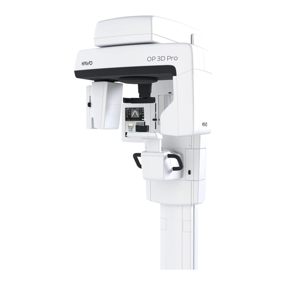
KaVo ORTHOPANTOMOGRAPH OP 3D Pro Service Manual
3d dental x-ray system
Hide thumbs
Also See for ORTHOPANTOMOGRAPH OP 3D Pro:
- Installation manual (168 pages) ,
- User manual (117 pages)

Related Manuals for KaVo ORTHOPANTOMOGRAPH OP 3D Pro


Summary of Contents for KaVo ORTHOPANTOMOGRAPH OP 3D Pro
- Page 1 ORTHOPANTOMOGRAPH™ OP 3D Pro 3D Dental X-ray System Service Manual ENGLISH 216508 rev. 1 0.805.5127...
- Page 3 Instumentarium Dental, PaloDEx Group Oy in the United States and/or other countries. KaVo™ is either registered trademark or trademark of Kaltenbach & Voigt GmbH in the United States and/or other countries. All other trademarks are property of their respective owners.
-
Page 5: Table Of Contents
............................1 Introduction........................1 1.1 ORTHOPANTOMOGRAPH™ OP 3D Pro ............1 1.2 Intended use ......................2 1.3 Associated documentation ..................2 1.4 References......................2 1.5 Abbreviations used in this manual ................ 3 1.6 Warnings and precautions ..................4 1.6.1 Warnings for cross infection............... 4 1.6.2 Warnings to be observed during installation and service...... - Page 6 3.5.19 EG200 Interface board................68 3.5.20 EG400 Panel power supply..............70 3.5.21 Panoramic sensor (CMOS) ..............71 3.5.22 3D sensor (CMOS)................... 71 3.5.23 Ethernet switch/router ................72 3.5.24 EC400 Collimator opto board..............73 3.6 Replacing the boards ..................74 Firmware description ....................81 4.1 Overview ......................
- Page 7 7.4.8 Error 22 Reading data from the 3D sensor failed........126 7.4.9 Error 23 Configuration data is invalid ............. 127 7.4.10 Error 24 Voltage (kV) failure in R3810 X-ray generator ......127 7.4.11 Error 25 Current (mA) failure in R3810 X-ray generator ......127 7.4.12 Error 26 Preheat failure in R3810 X-ray generator ........
- Page 8 7.6.3.3 ......N-, Collimator- or sensor swap not working161 7.6.3.4 ....CEPH sensor or secondary collimator not working162 7.6.3.5 .........The panorama imaging not working162 7.6.3.6 ............ The 3D imaging not working162 7.6.3.7 ..........The CEPH imaging not working163 7.6.3.8 ......R3220, R3300 or R3400 does not operate163 7.6.4 3D imaging ....................
-
Page 9: Introduction
1 Introduction Introduction 1.1 ORTHOPANTOMOGRAPH™ OP 3D Pro ORTHOPANTOMOGRAPH™ OP 3D Pro is a dental X-ray system for producing high quality digital images of dentition, TM-joints and skull. In order to take images with OP 3D Pro you need a suitable PC hardware connected to the OP 3D Pro unit and CLINIVIEW™... -
Page 10: Intended Use
3D Medium panel, H x W (optional) • 50 x 50 mm Field of View • 61 x 78 mm Field of View • 78 x 78 mm Field of View • 78 x 150 mm Field of View • 130 x 150 mm Field of View (optional) NOTICE! The FOV heights are maximum values measured at the center of the FOV, the measured heights at the... -
Page 11: Abbreviations Used In This Manual
1 Introduction • Cephalostat side changing instructions 1.5 Abbreviations used in this manual FOV = Field Of View. The cylindrical 3D volume that is reconstructed by the system. ROI = Region Of Interest. The anatomical area or region of the patient that you are interested to examine. FH = Frankfort-Horizontal H = HorizontalADC = Automatic Dose Control LDT = Low Dose Technology™... -
Page 12: Warnings And Precautions
1 Introduction 1.6 Warnings and precautions 1.6.1 Warnings for cross infection Always use available disposable protective covers with the patient positioning accessories: • Bite fork cover • Chin support cover • Head support cover • Nose support cover • Ear holder cover 1.6.2 Warnings to be observed during installation and service... - Page 13 1 Introduction If you have to leave the unit unattended with covers re- moved during servicing or maintenance, disconnect the unit from main power supply so that anyone who inadvertantly touches the unit does not receive an electric shock. This unit should only be used in areas that are provided with a protective earth connection to ensure an equipotential ground connection.
-
Page 14: Cautions For Electrostatic Discharge
1 Introduction 1.6.3 Cautions for Electrostatic discharge Electrostatic Discharge (ESD) can damage or destroy elec- tronic components. When servicing the device take precautions to avoid elec- trostatic build up and discharge (ESD). Follow the recom- mendations for the prevention of ESD that are used in the country in which you are working. - Page 15 1 Introduction Always ensure to fulfill the requirements of the local and na- tional regulations. The correct software and settings in the workstation are essential to the performance of the unit. Consult technical support to ensure correct setup. Danger - Explosion hazard Do not use in the presence of flammable anesthetics, gases or vapors.
- Page 16 1 Introduction When taking exposures, operators and service personnel must protect themselves from radiation and remain at least two meters (six feet) away from the unit during exposure. Protect the patient from scattered radiation by placing a protective lead apron over the patient. The unit must be installed and serviced according to the unit Installation &...
-
Page 17: Disclaimer
1 Introduction If this device is used with 3rd party imaging application software not supplied by the manufacturer, the 3rd party imaging application software must comply with all local laws on patient information software. This includes the Medical Device Directive 93/42/EEC and/or relevant legal requirements in the USA. - Page 18 1 Introduction...
-
Page 19: Unit Description
2 Unit description Unit description 2.1 Main parts and controls 1. Column 2. Carriage 3. Main support 4. Rotating unit 5. On/off switch (rear of carriage) and main fuses 6. Tubehead assembly 7. Touch screen display 8. Patient positioning panel 9. - Page 20 2 Unit description 1. Sensor holder (panoramic units without 3D option) 2. Panoramic sensor 1. 3D sensor (units with 3D option) 2. Panoramic sensor...
-
Page 21: Patient Positioning Lights
2 Unit description 2.2 Patient positioning lights 1. Midsagittal light 2. Frankfort horizontal (FH) light / Horizontal light, top of 130 mm high FOV (Medium Panel 3D option only) 3. Image layer light 4. Cephalometric FH light 5. TMJ light 6. - Page 22 2 Unit description Panoramic lights 1. Midsagittal light 2. FH light 1. Image layer 2. TMJ light...
- Page 23 2 Unit description Cephalometric lights (optional) 1. FH light 3D lights (optional) NOTICE! Appropriate lights are turned automatically on based on selected FOV. 1. Midsagittal light...
- Page 24 2 Unit description 2. Horizontal light, top of FOV NOTICE! With Medium Panel 3D option, Optional 130 mm height is indicated with Frankfort horizontal (FH) light. Move FH light to 130 mm position (locked in up- position). 3. Horizontal light, bottom of FOV...
-
Page 25: Patient Positioning Panel
2 Unit description 2.3 Patient positioning panel 1. Carriage UP 2. Carriage DOWN 3. Positioning lights ON/OFF 4. Patient positioning lights 5. Start position 6. Chin support UP 7. Chin support DOWN 8. Move the image layer anterior before exposure 3 mm, with sinus program 10 mm 9. -
Page 26: Main Control Panel
2 Unit description 2.4 Main control panel 1. Modality / imaging program section 2. Status of the unit 3. Settings 4. End examination 5. Automatic Dose Control 6. Manual mode 7. Test mode 8. Patient size selection 9. Exposure settings... -
Page 27: Unit Identification Labels
2 Unit description 2.5 Unit identification labels 1. Main label 2. 10A & 15A Fuse labels (next to the fuse holder) 3. Laser class 1 warning label IEC 60825-1:2007 4. Ethernet label 5. Sensors 6. (Primary) collimator label 7. (Secondary) cephalostat collimator label 8. -
Page 28: Unit Movements
2 Unit description 2.6 Unit movements Panoramic unit movements... -
Page 29: Finger Guards
2 Unit description Cephalometric unit movements 2.7 Finger guards If finger guards are installed incorrectly during the service, unit may get stuck in some extreme positions in N-movements. Correct installing of finger guards:... -
Page 30: Emergency Stop Switch
2 Unit description 1. These marks should be in this corner facing up. 2. part number 204373 / SP00374 3. part number 204374 / SP00374 4. part number 204375 / SP00374 2.8 Emergency stop switch In case of malfunction of the exposure button or other protective devices of the unit, an emergency stop switches are located near the handles and on the cephalostat unit, so that the patient can easily reach them. - Page 31 2 Unit description...
- Page 32 2 Unit description...
-
Page 33: Electrical Description
3 Electrical description Electrical description 3.1 Circuit boards There are three types of circuit board. Some versions may have different and/or additional boards. Logic boards Three logic boards: R3220 (Additional one in ceph) R3300 R3400 They all use FPGA chips and the embedded SW. - One touch screen display PC board. - Page 34 3 Electrical description Satellite boards Seven (nine in cephalostat models) optosensor boards: 5 x EG100 Dual opto board 2 x EE100 Ceph encoder opto board EC400 MFOV Collimator opto board Five (seven in cephalostat models) connector boards: EA100 DC Power distribution board EA200 AC Power distribution board EA300...
-
Page 35: Electrical Component Location
3 Electrical description 3.2 Electrical component location Circuit boards - Main unit SFOV Switch EG100 R5100 R5100 X-ray EB100 EG100 R5100 filter EG200 R5100 R5100 EG100 R3220 R5300 Laser R5100 EG100 ED100 microsw. R3710 EB200 R3300 EC100 R3810 GUI PC EG400 Laser Laser... - Page 36 3 Electrical description Circuit boards - Main unit MFOVl Switch EG100 R5100 R5100 X-ray EB100 EG100 R5100 filter EG200 Switch EG100 R5100 R5100 R5100 EG100 R3220 X-ray R5300 Laser R5100 EB100 EG100 R5100 filter EG100 ED100 EG200 microsw. R3710 EB200 R5100 R3300 EC100...
- Page 37 3 Electrical description Circuit boards - Cephalometric unit...
-
Page 38: List Of Circuit Boards And Electric Devices
3 Electrical description 3.3 List of circuit boards and electric devices Column Mains filter Warning light connector Exposure switch Ethernet Switch Carriage Touch screen display and PC MPQ200D Power supply EA100 Power distribution board EA200 Connector board R5300 Panel raw power supply R3300 R3400 IO2 + EA300 Connector board... - Page 39 3 Electrical description Main support Y-motor (3-phase stepper) Rotation motor (3-phase stepper) 2 x EG100 Dual opto board EB100 Rotator opto board Rotating unit (top part) EG200 Interface board 2 x R5100 3-phase stepper driver N-movement motor EG100 Dual opto board TMJ-laser Rotating unit (tubehead assembly) R3710...
- Page 40 3 Electrical description Cephalostat main assembly R3210 Ceph CPU EG200 Interface board R5300 Panel raw power supply R5100 3-phase stepper driver Cephalostat (Secondary collimator) EE100 Ceph encoder opto board S Motor (secondary collimator) FH laser Cephalostat (sensor head) EG400 Panel power supply EE100 Ceph encoder opto board EE200...
-
Page 41: Schematic Diagrams
3.4 Schematic diagrams Isolation diagram EA200 230V 100-240V VOLTAGE 120V 12Vrms ELECTRONICS SELECTION JUMPER 100V 12Vrms 12Vrms +24Vdc +5Vdc +12Vdc -12Vdc +5Vdc VOLTAGE MOTOR SIDE R3400 HOUSING DRIVE Z-MOTOR ELECTRONIC ISOLATION R3710 R3810 X-RAY X-RAY POWER SUPPLY X-RAY GENERATOR MAINS RECTIFICATION +360Vdc 360Vdc... - Page 42 Signalling 1 (OP 3D Pro small panel) OP300 SFOV WIRING DIAGRAM V1.1 SIGNALS SIGNALS Edited by PM 23.01.2014 C10901D C10901D 204790 204790 CBCT CBCT clk,ena,dir//N clk,ena,dir//N flat panel R5100 R5100 J5101 J5102 detector J5101 J5102 N-movement 3ph motor detector 204821 stepper mod 204821 204944...
- Page 43 Signalling 2 (OP 3D Pro small panel) stepper mod stepper mod R3200 J5102 J5102 Z-down,Z_ena R3300 J3201 J3205 IO 1 10/100 Mbps Gigabit ethernet J3307 205200 J3312 J3210 205202 204816 J3213 204820 10/100 Mbs J3202 J3211 J3302 J3315 10/100 Mbs 205029 J3311 J3313...
- Page 44 Signalling 1 (OP 3D Pro medium panel) 210247 SIGNALS clk,ena,dir//Coll2 R5100 J5101 J5102 C10900D 204790 210252 CBCT clk,ena,dir//N R5100 J5101 J5102 detector 204821 204944 J3215 J3204 210109 J3208 R5100 clk,ena,dir//Coll J5101 J5102 J3214 EC100 210251 R3220 204822 Rotator C10500D clk,ena,dir//Det R5100 J3203 JC104...
- Page 45 Signalling 2 (OP 3D Pro medium panel)( J3302 J3315 10/100 Mbs 205029 J3311 J3313 J3316 J3301 204816 204816 205896 204820 205490 JB007 JE007 JB007 JB008 204836 clk,ena,dir Y 3ph motor JB008 JG204 //COL M 205487 JG203 204818 204808 R5100 J5101 EG200 stepper mod JG205...
- Page 46 Low power wiring 1 (OP 3D Pro small panel) 207289 204800 205770 +24V EB200 EG200 Rotator R3210 J3215 JG216 JB201 JB203 XRAY IF +24V JG212 J3206 JG211 204857 JG209 204872 205444 204153 J3701 R3710 204154 mains X-ray +8Vdig C10901D +5Vana inlet JG405 JG406...
- Page 47 Low power wiring 2 (OP 3D Pro small panel) Semoflex Roboschlepp-C 201615 EC100 201614 +6V_A 4x1.5mm2 C10500D 204802 Conn. AGND Board +6V_D FF detector DGND J3801 J3802 J3806 PAN/CEPH module R3800 X-ray generator JB002 JB003 +6Vana Carriage GNDana C10502D 204848 +6Vdig 204809 FF detector...
- Page 48 Low power wiring 1 (OP 3D Pro medium panel) 210138 205770 EB200 +24V EG200 Rotator JG216 JB201 JB203 R3220 XRAY IF +24V JG212 J3206 JG211 204857 JG209 204872 205444 204153 J3701 R3710 204154 mains +8Vdig X-ray C10900D +5Vana inlet JG405 JG406 EG400 CBCT...
- Page 49 Low power wiring 2 (OP 3D Pro medium panel) J3805 FAN2 JB002 JB003 +6Vana Carriage GNDana C10502D 204848 +6Vdig 204809 EA200 connector 12Vac board JA210 J5302 JA208 J5301 205063 Transformer 12Vac JB006 J5301 12Vac J5302 Semoflex JA003 Roboschlepp-C 4x1.5mm2 JE001 205856 204795 205200...
- Page 50 Mains power wiring 1 (OP 3D Pro small panel) Edited by PM 23.01.2014 Sensor module Rotator XRAY PSU MAINS FILTER Protective Schaffner FN2090-8-06 earth R3700 Protective XRAY-PSU earth 204874 Protective earth 204151 Protective earth Ceph Y-movement Protective Protective Protective JB001 earth earth earth...
- Page 51 Mains power wiring 2 (OP 3D Pro small panel) (OP300 SFOV) Chin support MPQ-200D / Protective PBM200 Carriage earth 204884 Protective earth Protective JA203 Protective earth JA201 earth JA205 EA200 connector 204854 204859 board Mains switch 204869 JA202 204856 Mains 230/120/100Vac distribution 204860 /...
- Page 52 Mains power wiring 1 ( MFOV) Rotator XRAY PSU Protective earth R3710 Protective XRAY-PSU earth 204874 Protective earth 204151 Protective earth Ceph Y-movement Protective Protective Protective earth JB001 earth earth Protective earth Protective Protective earth earth AC-motor Protective PBM200 Carriage earth 204884 Protective...
- Page 53 Mains power wiring 2 JA205 EA200 204854 connector 204859 board Mains switch 204869 JA202 204856 Mains 230/120/100Vac distribution 204860 / Transformer 230Vac 205190 204873 Protective earth J3411 J3412 Protective earth R3400 Protective J3413 earth Protective earth 204839 204871 Column Z-motor 230Vac 204870 AC cable specification: Double insulation...
-
Page 55: Circuit Board Descriptions
3.5 Circuit board descriptions 3.5.1 R3220 CPU (Central Processing Unit) DESCRIPTION: There is one board in each base unit but two if the CEPH unit exists. The first one is for the central control of the unit including functions for panorama and 3D image acquisition as well as motion and x-ray control. -
Page 56: Ceph R3210
3.5.2 CEPH R3210 DESCRIPTION: CEPH image capturing, Image buffering in the DDRAM memory, Image calculation, Sensor motion signaling, Secondary collimator motion signaling FUSES: None INDICATOR LEDS: Giga Ethernet status indicators: Duplex mode 100MB 10MB Link activity 100Meg Ethernet status indicators: 100MB Link activity Link OK... -
Page 57: R3300 Io1 (Input/Output 1)
3.5.3 R3300 IO1 (Input/Output 1) DESCRIPTION: IO board used mainly for interfacing with stepper motors and lights. Includes an FPGA integrated circuit and embed- ded SW. LOCATION: In the column / carriage. FUNCTIONS: Rotation motor and position detection X motor and position detection Y motor and position detection Layer, FH, Midsagittal and 3D lights Mains voltage measurement... -
Page 58: R3400 Ngeo Io2 (Input/Output 2 Board)
3.5.4 R3400 NGEO IO2 (Input/Output 2 Board) WARNING! Dangerous mains voltage on part of this board. The dangerous part is marked with crosshatched lines. LA1 also indicates when there is live voltage on the board. DESCRIPTION: The operation of external IO2 board is controlled via the in- ternal Ethernet. - Page 59 INDICATOR LEDS: 3.3V 1.25V Exposure switch pressed indicator Z-ENA_ETH Z-DOWN_ETH Z-UP_ETH Z-UP Z-DOWN Z-ENA Z-LOW LIMIT Z-UPPER LIMIT Ethernet LINK OK Ethernet Speed (On=100MB, Off=10MB) Ethernet Transferring Activities TEST PINS: +3,3V...
-
Page 60: R3710 X-Ray Power Supply
3.5.5 R3710 X-Ray power supply WARNING! Dangerous mains voltage on part of this board. LA1 also indicates when there is live voltage on the board. DESCRIPTION: Generates the voltages for the R3700 X-ray Generator. LOCATION: In the tubehead side of the rotating unit. FUSES: T2A 250V FF8A 500V... -
Page 61: R3810 X-Ray Generator
3.5.6 R3810 X-Ray generator WARNING! Dangerous mains voltage on part of this board. LA1 also indicates when there is live voltage on the board. DESCRIPTION: The board has two main functions: To generate 360Vp-p AC voltage for tubehead from the mains supply voltage, 230 VAC, and to generate the fila- ment voltage for the tubehead and the feedback signals. - Page 62 TEST PINS: HVGND High Voltage (HV) BRIDGE FETDRIVE FETAD HV BRIDGE FETDRIVE FETBC FAN_OVERRIDE, Not assembled Exposure Enabled (EXPENA) KVFB KVREF Not for service use TP10 TP11 PREHREF TP12 MAREF TP13 MAFB TP14 Not for service use TP15 PREHFB TP16 kVfb = 20 kV/V (eg.
-
Page 63: R5100 3-Phase Stepper Driver
3.5.7 R5100 3-Phase stepper driver DESCRIPTION: Is used to drive a stepper motor according to a digital input signal. LOCATION: Close to each stepper motor. FUSES: None INDICATOR LEDS: +28V TEST PINS: Vref... -
Page 64: R5300 Panel Raw Power Supply
3.5.8 R5300 Panel raw power supply DESCRIPTION: There is one board in each base unit but two if the CEPH unit exists. The first one generates +8V low voltage for the analog side of the 3D and panorama sensor power chains. The second one generates +8V low voltage for the analog side of the CEPH sensor power chains. -
Page 65: Ea100 Power Distribution Board
3.5.9 EA100 Power distribution board DESCRIPTION: EA100 removes noise from the PSU output (MPQ200D or equivalent) and distributes it to various parts of the system. Digital +8V raw panel voltage is also regulated from +12V input. Board includes two 12V-connectors for chassis fans. LOCATION: In the bottom part of the column inside metal shield box together with EA200 and the PSU. - Page 66 INDICATOR LEDS: +24V -12V +12V JUMPERS: JP1 1&2, 3&4 shorted: regulate +8V from SMPS (normal operation) JP2 1&2, 3&4 shorted: regulate +8V from +12Vac input NOTE! Do not install jumpers on JP1 & JP2 simultaneously! TEST PINS: +5V IN +24V IN -12V IN +12V IN +5V OUT...
-
Page 67: Ea200 Connector Board
3.5.10 EA200 Connector board DESCRIPTION: The main function is to distribute AC voltage from the mains switch (main power supply) to the: - 100/120/230/12Vac transformer - to MPQ-200D/PBM200 power supply - to R3700 X-ray power supply EA200 is also used as a connector board for EXP signal disribution(to R3400/EG200) and a relay for the external warning light. - Page 68 INDICATOR LEDS: indicates the existence of the 12Vac mains volt- age measuring voltage. TEST PINS: Ground Test point for secondary side grounding. NOTE! Not suitable for measuring the mains side grounding. EA200 Block diagram...
-
Page 69: Ea300 Connector Board
3.5.11 EA300 Connector board DESCRIPTION: Is used as an interface between the R3400 NGEO IO2 and patient positioning panels. LOCATION: Daughter board for the R3400 NGEO IO2 FUNCTIONS: Emergency stop interface (chin support) Emergency stop interface (CEPH). Patient positioning left side panel interface. Patient positioning right side panel interface. -
Page 70: Ec100 Pan Sensor Connector Board
DESCRIPTION: OUTPUTS: Optoswitch outputs INDICATOR LEDS: None TEST PINS: None 3.5.13 EC100 Pan sensor connector board DESCRIPTION: EC100 routes image data from the panoramic x-ray image sensor assembly and provides operating voltages and con- trol signals to the sensor. Device-side connector that docks the sensor to the main unit is mounted on this board. -
Page 71: Ed100 Pan Sensor Connector Board
3.5.14 ED100 Pan sensor connector board DESCRIPTION: ED100 routes image data from the panoramic x-ray image sensor and provides operating voltages and control signals to the sensor. Connector that docks the sensor to the main unit is mounted on this board. LOCATION: Inside panoramic x-ray image sensor. -
Page 72: Ed200 Ceph Sensor Connector Board
3.5.15 ED200 Ceph sensor connector board DESCRIPTION: ED200 routes image data from the cephalometric x-ray im- age sensor and provides operating voltages and control signals to the sensor. Connector that docks the sensor to the main unit is mounted on this board. LOCATION: Inside cephalometric x-ray image sensor. -
Page 73: Ee100 Ceph Encoder Opto Board
3.5.16 EE100 Ceph encoder opto board DESCRIPTION: EE100 has three optoswitches and is used for cephalostat head sensor position and secondary collimator position (HOME, ENC_A, ENC_B) detection. LOCATION: Two in the cephalostat head; one in moving sensor assem- bly, another one in moving secondary collimator assembly. FUNCTIONS: Three optoswitches for position detection. -
Page 74: Ee200 Ceph Sensor Connector Board
3.5.17 EE200 Ceph sensor connector board DESCRIPTION: EE200 routes image data from the cephalometric X-ray im- age sensor assembly and provides operating voltages and control signals to the sensor. Device-side connector that docks the sensor to the main unit is mounted on this board. LOCATION: In the cephalometric sensor mount assembly. -
Page 75: Eg100 Dual Opto Board
3.5.18 EG100 Dual opto board DESCRIPTION: EG100 has two optoswitches and is used for position (LIM- IT, MIDDLE) detection in various movements of the unit. LOCATION: Two in the upper shelf (X-, Y-movements). Two in the rotat- ing unit (N-, Collimator-movements). One in the lower shelf (Chin support movement). -
Page 76: Eg200 Interface Board
3.5.19 EG200 Interface board DESCRIPTION: EG200 is a general I/O-board and includes electronics for controlling the X-ray generator. There are two pcb’s in each unit. LOCATION: In the top part of the rotating unit and inside of the cephalo- head. FUNCTIONS: X-ray generator control EXP signal interface... - Page 77 INDICATOR LEDS: +28V +5V Xray +3.3V Xray Ena Preh Ena Exp Ena TEST PINS: TP1,3 POWGND...
-
Page 78: Eg400 Panel Power Supply
3.5.20 EG400 Panel power supply DESCRIPTION: Generates the low voltages for the PAN/CEPH and 3D sen- sors.The board regulates the voltages, 8V analog to 6V or 5V analog and 8V digital to 6V or 5V digital, depending on what mode is used. There are also power enables in the cir- cuit. -
Page 79: Panoramic Sensor (Cmos)
3.5.21 Panoramic sensor (CMOS) DESCRIPTION: Panoramic image acquisition. LOCATION: Rotating unit (sensor head) FUSES: None INDICATOR LEDS: None 3.5.22 3D sensor (CMOS) DESCRIPTION: 3D image acquisition. LOCATION: Rotating unit (sensor head) FUSES: None INDICATOR LEDS: None... -
Page 80: Ethernet Switch/Router
3.5.23 Ethernet switch/router DESCRIPTION: Ethernet traffic routing LOCATION: In the upper shelf. FUSES: None INDICATOR LEDS: D1-D5 OFF = no connection ON = link connection OK (no traffic) FLASH = link connection OK (traffic) -
Page 81: Ec400 Collimator Opto Board
3.5.24 EC400 Collimator opto board DESCRIPTION: EC400 has four optoswitches and is used for collimator po- sition (HOME 1, HOME 2, LIM1, LIM2) detection. LOCATION: In the rotating unit (Collimator movements). FUNCTIONS: Four optoswitches for position detection. INPUTS: +3.3Vdc for optoswitch LEDs OUTPUTS: Optoswitch outputs INDICATOR LEDS:... -
Page 82: Replacing The Boards
3.6 Replacing the boards Following is a list what should be checked/calibrated after replacing certain parts on the system. In addition, Quality Check (QC) images of all modalities should be taken and inspected every time after replacing any part on the system. - Page 83 R3210 CPU Board (ceph) Upgrade the unit’s embedded software. Use automatic update to ensure all software components are compat- ible. The R3210 CPU board must be separately updat- ed before a full update is done if the replacement board is not preprogrammed with R3210 Ceph CPU software. Instructions on how to do this are included in the soft- ware release package.
- Page 84 Panoramic image sensor Pan collimator calibration Pan geometry calibration Pan pixel calibration 3D image sensor 3D collimator calibration Pan collimator calibration 3D geometry calibration 3D pixel calibration Ceph image sensor Ceph rot angle calibration Ceph mech adj calibration Ceph pix calibration Tubehead Perform full calibration of the unit (starting with preheat and mA calibrations)
- Page 85 WARNING! Only authorized technician is allowed to do these changes! Open lower carriage covers to access to EA200 board. Remove cable 207286 (J3, JA211 and JA209). Attach cable 204862 (JA209) to connector JA209 on the EA200 board. Connection box changes on the column base are de- scribed in the following picture.
- Page 86 CSA) is in the units F3 fuse holder. Remove cable 207263.Insert the external warning light to the two left-most terminals. Check the F3 fuse.
-
Page 89: Firmware Description
Firmware description 4.1 Overview The firmware is located on four components: R3220 CPU: Main control, image acquisition, UDP/IP interface to the acquisition PC, collimator, sensor and n (rotation center offset) motor control. R3210 Ceph: Ceph movement control and ceph image acquisition. R3300 IO1: rotation, x and y motor control, posi- tioning lights. -
Page 90: Detailed View
4 Firmware description 4.2 Detailed View R3220 CPU Executes the main and boot SW of the unit. Boot software Loads the main software into the RAM and starts it. Handles the initial unit software loading and boot mode updates. Main software Controls and coordinates unit movements, exposure, image acquisition and transfer. -
Page 91: Operating Modes
4 Firmware description 4.3 Operating modes Imaging mode The usual operation mode. X-ray imaging is allowed when patient study is started. Test mode Same as the normal imaging mode, except that the X-ray generator is disabled. The image is grabbed but not sent to the driver. -
Page 92: Firmware States
4 Firmware description 4.4 Firmware states IO cards only have one state. The IO cards wait for commands from the main CPU. After they receive a command they execute the command and send an acknowledgment of its execution to the main CPU. CPU board (R3220) has several states that perform various checks during operation of the system. - Page 93 4 Firmware description Init (initialization) state During the initialization state the unit carries out several initializations and checks as follows: detects the IO boards initializes the generator initializes the collimator initializes the image buffer and calibration data checks states of the sensors checks the state of the exposure button initializes the movements Most of the essential functionality of the unit is tested...
- Page 94 4 Firmware description Idle state The unit is waiting for an examination to be started by the driver. The service state can be entered during this state The unit will enter the error state if a system error occurs. Select (program select) state The unit initializes the selected program and enters the ready state when system is ready to take an exposure.
- Page 95 4 Firmware description Error state The unit will enter the error state whenever a system error is encountered. Movements and x-rays are stopped as a precaution. The error log is updated. Service state may be entered using the s2terminal for further diagnosis. Service state The service state (s2terminal) is entered by giving the service command when the unit is in the error state or idle...
- Page 96 4 Firmware description...
-
Page 97: Hardware Operation
Note! The emergency switch does not cut the power off anywhere else. Emergency Switch EA300 R3400 +3v3 J3401 JA302 JA303 ES_ON U16-4 JA304 JB006 FPGA Z-motion Control circuitry NOTE! Cephalostat emergency stop wiring is added here when cephalostat is installed. 216508 rev 1 NEW KAVO... -
Page 98: Movements
The unit has seven motorized movements. The collimator movements are automatic, but all the other movements are controlled by the user with the remote control and the exposure switch. The Z-movement is double secured with HW (single fault tolerant). 5.3 Rotation movement NEW KAVO 216508 rev 1... -
Page 99: X-Movement
Eth PHY Wo/i JA206 1 X-motor J3307 +24V EA200 100Mb 1 ... Eth PHY DGND Ethernet Switch Legends CPU BOARD R3220 HW/SW functional block J3211 100Mb Cable item code Control 1 ... 2xxxxx Eth PHY 216508 rev 1 NEW KAVO... -
Page 100: Y-Movement
5 Hardware operation 5.5 Y-movement R3400 R3300 J3302 PIO_x PIO_x PIO_x Control J3312 +24V J3307 100Mb R3220 NEW KAVO 216508 rev 1... -
Page 101: Z-Movement
5 Hardware operation 5.6 Z-movement 216508 rev 1 NEW KAVO... -
Page 102: Chin Rest Movement
EA300 J3403 100Mb 1 ... Ethernet Switch Eth PHY J3406 JG101 CPU BOARD EG100 Chin rest position R3220 Optos J3211 100Mb Control 1 ... Eth PHY Legends HW/SW functional block 2xxxxx Cable item code NEW KAVO 216508 rev 1... -
Page 103: Collimator Movement
5 Hardware operation 5.8 Collimator movement 216508 rev 1 NEW KAVO... -
Page 104: Pan Sensor Movement
+28V motor J5102 PGND Uo/i J3203 HI_CURR PIO_x Vo/i Control PIO_x Wo/i Detector Optos PIO_x +28V JG101 EG200 EG100 J3213 DGND JG204 JG205 16 +5V Shift register Legends HW/SW functional block Cable item code 2xxxxx NEW KAVO 216508 rev 1... -
Page 105: Secondary Collimator Movement
5 Hardware operation 5.10 Secondary collimator movement 216508 rev 1 NEW KAVO... -
Page 106: Ceph Sensor Movement
5 Hardware operation 5.11 Ceph sensor movement NEW KAVO 216508 rev 1... -
Page 107: Imaging Chain
5 Hardware operation 5.12 Imaging chain 5.12.1 3D imaging chain 216508 rev 1 NEW KAVO... -
Page 108: Panoramic Imaging Chain
5 Hardware operation 5.12.2 Panoramic imaging chain NEW KAVO 216508 rev 1... -
Page 109: Cephalometric Imaging Chain
5 Hardware operation 5.12.3 Cephalometric imaging chain 216508 rev 1 NEW KAVO... -
Page 110: Exposure Control
5 Hardware operation 5.12.4 Exposure control NEW KAVO 216508 rev 1... -
Page 111: Exposure Warning Light
EA100 J3419 JA216 JA209 R3400 Exposure Tangent JA207 JA206/204 To EG200 / EA300 Legends Implemented by HW VHDL Implemented by VHDL in the FPGA Implemented by Nios SW in the FPGA Cable item code 2xxxxx 216508 rev 1 NEW KAVO... - Page 112 5 Hardware operation NEW KAVO 216508 rev 1...
-
Page 113: The S2Terminal And Service Functions
The s2terminal and service functions The s2terminal, service terminal application, allows the operation of the unit to be checked, tested and configured and firmware to be upgraded. There are three types of s2terminal commands: s2terminal commands, allow the s2terminal to download raw images and upgrade firmware unit state commands, allow the states of the unit to be check and changed. -
Page 114: Opening The S2Terminal
6 The s2terminal and service functions 6.1 Opening the s2Terminal Opening the s2terminal from the release package Copy the software release package to the host PC and unzip it. Locate openS2.bat in the unzipped release package and double click it. You will be prompted for unit’s IP address. -
Page 115: S2Terminal Commands
6 The s2terminal and service functions 6.2 s2terminal commands These commands allow images to be downloaded directly from the unit memory and the unit reserved if more than one client (an s2terminal or driver in the same PC or another PC) is connected to the unit. Additional commands (under help) allow firmware to be updated. - Page 116 6 The s2terminal and service functions Mode NORMAL ------------------------------------------------------------------ The text NORMAL will appear which indicates that the s2terminal has released the unit so that the dental im- agine software can be used to take an image when the image capture is activated. 2.
-
Page 117: Unit State Commands
6 The s2terminal and service functions 6.3 Unit state commands The unit state commands, allow the states of the unit to be checked and changed. Note! Some of unit state commands can also be accessed when the unit is in service mode. status r This command shows the current state of the unit. - Page 118 6 The s2terminal and service functions off state indicates that firmware upgrades have been completed and the unit must be restarted for the upgrades to be activated. cancel Skips the current initialization phase, i.e. initialization of calibration data or initialization movements. This will allow the unit to go from state init to idle without all initialization being done.
-
Page 119: Unit Service Commands
6 The s2terminal and service functions 6.4 Unit service commands The unit service commands allow the operation of the unit to be checked and configured. 1. Key in service and press ENTER. ------------------------------------------------------------------ service ------------------------------------------------------------------ The unit enters and activates the service state. Note! The unit can only enter the service state from the idle or error states. - Page 120 6 The s2terminal and service functions Displays the log entries. Displays unit’s firmware version informa- login tion Adds a comment to the log logsign Performs a memory test on image memo- memtest ry area. Runs a motor test. motortest Starts fake study without using driver patient Prints position information of selected posprint...
- Page 121 6 The s2terminal and service functions ------------------------------------------------------------------ demomode 0 ------------------------------------------------------------------ sets the unit to normal operating mode. ------------------------------------------------------------------ 5. To close the s2terminal key in xq and then press ENTER. ------------------------------------------------------------------ ------------------------------------------------------------------...
- Page 122 6 The s2terminal and service functions...
-
Page 123: Error Codes And Troubleshooting
Error codes and troubleshooting 7.1 Initial actions Note! Blurring can occur on the upper corners of the cylin- derical 3D volume. Nevertheless, the best possible image quality relative to the selected resolution is presented. Error codes When an error code appears on the display the unit will stop working and cannot be operated while the error code is on the display. - Page 124 7 Error codes and troubleshooting s2terminal command: Downloading raw images - xi, these images can be use for troubleshooting. Refer to section, The s2terminal and service functions. Checking circuit boards Circuit boards cannot be repaired in the field. Some boards have fuses that can be replaced.
- Page 125 7 Error codes and troubleshooting Make sure that all cables are correctly and securely attached to their respective connectors. Connectors must not be loose or misaligned. If the connector has a locking mechanism make sure that it is locked. If you fi nd a loose or misaligned connector, disconnect it and check for bent, broken or missing pins.
-
Page 126: Reporting Problems To Technical Support
7 Error codes and troubleshooting 7.3 Reporting problems to technical support If you need to contact technical support, please gather the information listed below. This information is absolutely crucial for diagnosing the problem. Type of problem Needed type of information Image quality Problem description Exported example images... - Page 127 7 Error codes and troubleshooting • What were you or the user doing when the problem occurred? • Did the problem occur once or repeatedly? How often? At any special occasion? Exported example images Refer to the documentation of the imaging software used for instructions on how to export images.
- Page 128 7 Error codes and troubleshooting ue to 2. Save and close the file. Restart the workstation. Raw files of images processed will be stored under the path C:\ProgramData\Dxr120\Raw. To disable saving of raw files again, repeat the steps listed above, but change the tag value back to 0 or restore the original file.
- Page 129 7 Error codes and troubleshooting Image acquisition driver logs Image acquisition driver logs located under C:\ProgramData\Dxr120\ and contain information related to transfer and processing. Zip all files located in this folder when reporting an image acquisition related problem. S2terminal log The S2terminal log contains information about what’s going on in the X-ray unit and is only written when an s2terminal is connected to the X-ray unit in logging mode.
-
Page 130: Error Code Descriptions
7 Error codes and troubleshooting Download the logs using command xdl. After download the GUI logs are located in a zip package named logs.zip in the s2terminal folder. 7.4 Error code descriptions 7.4.1 Error 4 Rotator home position was not found Belt(s) slipping. -
Page 131: Error 5 Exposure Was Taking Too Long And A Timeout Occured
7 Error codes and troubleshooting 7.4.2 Error 5 Exposure was taking too long and a timeout occured Main CPU board faulty. CAUSE A Replace the main CPU board. SOLUTION A An internal error has occurred. CAUSE B Update to the latest software version. Please notify SOLUTION B technical support about the situation in which the error occurred. -
Page 132: Error 9 R3300 Io1 Board Is Not Functioning
7 Error codes and troubleshooting 7.4.4 Error 9 R3300 IO1 board is not functioning Communication between the main CPU and R3300 CAUSE A is not working properly. • The Ethernet cable between the R3300 and the SOLUTION A internal Ethernet switch may be faulty. Try with a spare cable and replace the cable if needed. -
Page 133: Error 12 R3400 Io2 Board Is Not Functioning
7 Error codes and troubleshooting 7.4.5 Error 12 R3400 IO2 board is not functioning Communication between the main CPU and R3400 CAUSE A is not working properly. • The Ethernet cable between the R3400 and the SOLUTION A internal Ethernet switch may be faulty. Try with a spare cable and replace the cable if needed. -
Page 134: Error 21 Calibration Data Receive Timeout
7 Error codes and troubleshooting 7.4.7 Error 21 Calibration data receive timeout The main CPU did not receive calibration data from CAUSE A the GUI PC in time. • Timeout due to communication problems. See Er- SOLUTION A ror 100 for hints on how to trouble shoot cables and Ethernet switch. -
Page 135: Error 23 Configuration Data Is Invalid
7 Error codes and troubleshooting 7.4.9 Error 23 Configuration data is invalid Unit configuration data stored in the main CPU CAUSE A board is missing or corrupted. Recalibrate the unit. Replace the main CPU board SOLUTION A if the problem reoccurs. 7.4.10 Error 24 Voltage (kV) failure in R3810 X-ray generator... -
Page 136: Error 26 Preheat Failure In R3810 X-Ray Generator
7 Error codes and troubleshooting 7.4.12 Error 26 Preheat failure in R3810 X-ray generator The preheat feedback signal from the generator is out of range. See also Error 6. The exposure enable signal is not reaching the X- CAUSE A ray generator. -
Page 137: Error 30 Cpu Firmware Is Corrupted
7 Error codes and troubleshooting 7.4.15 Error 30 CPU firmware is corrupted The configuration flash memory is corrupted due to CAUSE A HW problems, a failure during programming, or the configuration being reset using service command “confreset all”. Update the unit’s embedded software. Replace the SOLUTION A main CPU board if the error reoccurs. -
Page 138: Error 33 Movement Of C (Collimator) Motor Failed
7 Error codes and troubleshooting 7.4.18 Error 33 Movement of C (collimator) motor failed The collimator is not moving correctly. CAUSE A The movement not working correctly may be due to SOLUTION A a fault in the • motor, • motor cable, •... -
Page 139: Error 34 Movement Of D (Sensor) Motor Failed
7 Error codes and troubleshooting 7.4.19 Error 34 Movement of D (sensor) motor failed The sensor is not rotating correctly. CAUSE A The movement not working correctly may be due to SOLUTION A a fault in the • motor, • motor cable, •... -
Page 140: Error 35 Movement Of J (Chin Support) Motor Failed
7 Error codes and troubleshooting 7.4.20 Error 35 Movement of J (chin support) motor failed The chin support is not moving correctly. CAUSE A The movement not working correctly may be due to SOLUTION A a fault in the • motor, •... -
Page 141: Error 36 Movement Of N Motor Failed
7 Error codes and troubleshooting 7.4.21 Error 36 Movement of N motor failed The rotator is not moving correctly in N direction. CAUSE A The movement not working correctly may be due to SOLUTION A a fault in the • motor, •... -
Page 142: Error 37 Movement Of R (Rotation) Motor Failed
7 Error codes and troubleshooting 7.4.22 Error 37 Movement of R (Rotation) motor failed The rotator is not moving correctly. CAUSE A The movement not working correctly may be due to SOLUTION A a fault in the • motor, • motor cable, •... -
Page 143: Error 38 Movement Of X Motor Failed
7 Error codes and troubleshooting 7.4.23 Error 38 Movement of X motor failed The X movement is not working correctly. CAUSE A The movement not working correctly may be due to SOLUTION A a fault in the • motor, • motor cable, •... -
Page 144: Error 39 Movement Of Y Motor Failed
7 Error codes and troubleshooting 7.4.24 Error 39 Movement of Y motor failed The Y movement is not working correctly. CAUSE A The movement not working correctly may be due to SOLUTION A a fault in the • motor, • motor cable, •... -
Page 145: Error 40 Movement Of S (Secondary Collimator) Motor Failed
7 Error codes and troubleshooting 7.4.25 Error 40 Movement of S (secondary collimator) motor failed There is a problem with the S position detection. CAUSE A Use service program “cephstatus” to check the en- SOLUTION A coder status. Move the secondary collimator back and forth and verify that the encoder value chang- es. -
Page 146: Error 41 Movement Of T (Cephalostat Sensor) Motor Failed
7 Error codes and troubleshooting 7.4.26 Error 41 Movement of T (cephalostat sensor) motor failed There is a problem with the T position detection. CAUSE A Use service program “cephstatus” to check the en- SOLUTION A coder status. Move the sensor back and forth and verify that the encoder value changes. -
Page 147: Error 42 Ceph Io Board Is Not Functioning
7 Error codes and troubleshooting 7.4.27 Error 42 Ceph IO board is not functioning The main CPU cannot communicate with the ceph- CAUSE A alostat CPU. • Check proper connection of the SOLUTION A Ethernet cable 205896 between the 10/ 100 Mb/s connector (J3211, not J3220!) of the ceph CPU and JE007. -
Page 148: Error 43 Serial Io Board Error
7 Error codes and troubleshooting 7.4.28 Error 43 Serial IO board error The EG200 XRAY IF board or the cable 204798 CAUSE A (between R3220 and EG200) is faulty. Check that the cable is properly connected. Re- SOLUTION A place the cable and/or the EG200 XRAY IF board. 7.4.29 Error 44 Mirror door open The mirror door is open. -
Page 149: Error 46 Emergency Stop Button Is Pressed
7 Error codes and troubleshooting 7.4.31 Error 46 Emergency stop button is pressed The emergency stop button is activated. CAUSE A Release emergency stop button and dismiss the SOLUTION A error message. If the unit is equipped with a ceph- alostat, emergency may also be activated from the cephalostat. -
Page 150: Error 47 Button Stuck
7 Error codes and troubleshooting 7.4.32 Error 47 Button stuck Button stuck. Error 47 One or more buttons are stuck. CAUSE A Use service program “systemstatus” to determine SOLUTION A which button is not reacting (is stuck) to being pressed. Replace keypad(s) if needed. Note that the button stuck may also be in the cephalostat. -
Page 151: Error 49 Reading Panoramic Sensor Data Failed
7 Error codes and troubleshooting 7.4.34 Error 49 Reading panoramic sensor data failed The sensor is not properly connected. CAUSE A Lift the lever at the side of the panoramic sensor, SOLUTION A and firmly push it back. The connection between the sensor and the sensor CAUSE B holder is bad. -
Page 152: Error 50 Reading Cephalostat Sensor Data Failed
7 Error codes and troubleshooting 7.4.35 Error 50 Reading cephalostat sensor data failed The sensor is not properly connected. CAUSE A Lift the lever at the side of the cephalostat sensor, SOLUTION A and firmly push it back. The connection between the sensor and the sensor CAUSE B holder is bad. -
Page 153: Error 51 Cephalostat Sensor Missing
7 Error codes and troubleshooting 7.4.36 Error 51 Cephalostat sensor missing Cephalostat sensor removed during imaging. CAUSE A Reattach the sensor. SOLUTION A The sensor is not properly connected. CAUSE B Lift the lever at the side of the cephalostat sensor, SOLUTION B and firmly push it back. -
Page 154: Error 52 Movement Of L-Motor Failed
7 Error codes and troubleshooting 7.4.37 Error 52 Movement of L-motor failed The L-motor is not moving correctly. CAUSE A The movement not working correctly may be due to SOLUTION A a fault in the - motor - motor cable - R5100 Stepper driver module - cable between the stepper driver and the CPU board. -
Page 155: Error 100 Internal Communication Bus Error
7 Error codes and troubleshooting 7.4.38 Error 100 Internal communication bus error The GUI PC cannot communicate with the main CAUSE A CPU board. • Check that the cable between the main CPU and SOLUTION A internal Ethernet switch is properly connected and not damaged. -
Page 156: Gui Error 103 External Gui Not Connected
7 Error codes and troubleshooting 7.4.40 GUI Error 103 External GUI not connected Device not connected to the PC. CAUSE A Check that ethernet cable is connected between SOLUTION A the device and PC. If ethernet cable is properly plugged check the ethernet configuration that IP, Subnet mask and Gateway are correctly config- ured. -
Page 157: Warnings And Notifications
7 Error codes and troubleshooting 7.5 Warnings and notifications Please press any button to complete unit start up The unit needs the operators acknowledgement to CAUSE A start initialization movements. Press any button on the patient positioning panel to SOLUTION A start movement initialization. - Page 158 7 Error codes and troubleshooting Use service program “readadc” to determine SOLUTION E whether the temperature is measured correctly. ADC value 111 corresponds to the maxi- mum allowed temperature (75 deg Celsi- us). Lower ADC values indicate a incorrectly calibrated measurement. Ad- just trimmer R66 in the EG200 XRAY IF board until approximately 200 is read as ADC value at room temperature.
- Page 159 7 Error codes and troubleshooting Run 3D geometry calibration, 3D pixel calibration SOLUTION A and 3D QC. Running the corresponding panoramic calibrations is also recommended. Mains voltage is out of range Too low or high mains voltage connected to the CAUSE A unit.
- Page 160 7 Error codes and troubleshooting The unit is not fully calibrated for the selected program One or more calibrations needed by the selected CAUSE A program are not competed. Switch to the service / quality assurance view in the SOLUTION A GUI to find out which calibration is not done.
- Page 161 7 Error codes and troubleshooting Check if the diagnostic value of the resulting image SOLUTION A is sufficient. Take another image if needed. Exposure button is pressed The exposure button is pressed after imaging has CAUSE A ended or during startup. Release the exposure button.
- Page 162 7 Error codes and troubleshooting Head support is in wrong position <ID, KAVO, GDX only> The head support position is not valid for the select- CAUSE A ed imaging program. Lift the head support to the upmost position. SOLUTION A...
- Page 163 7 Error codes and troubleshooting Check if the diagnostic value of the resulting image SOLUTION A is sufficient. Take another image if needed.
-
Page 164: Hardware Trouble Shooting
7 Error codes and troubleshooting 7.6 Hardware trouble shooting 7.6.1 Internal and external LANs 7.6.1.1 No Ethernet connection between the unit and the workstation • See if the problem can be resolved by restarting the X-ray unit and the workstation. •... -
Page 165: Connection Between The Workstation And X-Ray Unit Is Lost From Time To Time
7 Error codes and troubleshooting • Check for problems related to the R3220 Main CPU. Measure the input voltage to the R3220 (min 4.5 V). If the voltage is OK, then replace the R3220 main CPU board. Otherwise refer to the instruc- tions for power distribution trouble shooting. -
Page 166: Power Distribution (Mains)
7 Error codes and troubleshooting 7.6.2 Power distribution (mains) 7.6.2.1 Nothing happens when the X-ray unit is switched on • Check that the mains cord is connected to the wall socket. If not, plug it in. • Check that there is mains power reaching the wall socket. -
Page 167: Power Distribution (Low Voltages)
7 Error codes and troubleshooting If not then check that voltages exist on input of the generator filter. If not, replace mains cabling. If voltages exist, replace filter. If the lamp is on check lamp (LA1) on R3810 (X-ray generator). -
Page 168: Y- Or Rotator Not Working
7 Error codes and troubleshooting If not, replace EA100. If after replacing EA100 the LEDs still do not come on, replace the low power supply. If LEDs are on after un-plugging some of the connectors, then fol- low the power distribution chain in question by cutting it step-by-step until the LED in question goes... -
Page 169: N-, Collimator- Or Sensor Swap Not Working161
7 Error codes and troubleshooting If indicator is on, measure +24V voltage from J3311, J3313 or J3314. Replace R3300 if there is no volt- age. If indicator is on, measure +24V voltage from J5101. Replace cable between J5101 and R3300 if there is no voltage. -
Page 170: Ceph Sensor Or Secondary Collimator Not Working162
7 Error codes and troubleshooting 7.6.3.4 CEPH sensor or secondary collimator not working • Follow instructions in chapter 7.6.3.3. 7.6.3.5 The panorama imaging not working • Switch the X-ray unit ON, select the service mode from the s2Terminal and type the command panelpower Panoramic 1 to switch pan sensor power ON: Check all the LEDs on EG400. -
Page 171: The Ceph Imaging Not Working163
7 Error codes and troubleshooting If all the LEDs are on and the voltages are OK and R3220 has been replaced. Measure voltage from JG403 (PAN-pow- er feed). If voltages are present, replace EG400. If not, replace CT sensor. If non or some of LEDs are on, follow the trouble shooting instructions above. -
Page 172: Generally Poor Image Quality
7 Error codes and troubleshooting 7.6.4.2 Generally poor image quality • Recalibrate the unit. • Check condition of the power feed by following trouble shooting guide 7.6.3.6 for 3D imaging not working. • Follow instructions in guide 7.6.4.1 to localize mal- functioning component. -
Page 173: Image Is Messy
7 Error codes and troubleshooting R3220. PAN sensor. 7.6.5.2 Image is messy • Check condition of the power feed by following trouble shooting guide 7.6.3.5 for Panorama imag- ing not working. 7.6.5.3 Image is too dark or light •... - Page 174 7 Error codes and troubleshooting If the LED now comes on, replace the connector to JG206 and remove JA206 from EA200 and short circuit pins 1 and If the LED does not come on, re- place cable JA206 JG206 ...
-
Page 175: Exposure Sequence Starts But No X-Rays Are Generated
7 Error codes and troubleshooting If LED D6 does not come on, check the condition of the cable between J3202 and JG206. If the cable is OK, replace EG200. If not, replace cable. If LED D6 comes on, the exposure switch is OK. -
Page 176: X-Ray Generation
7 Error codes and troubleshooting If the voltage goes above 2V re- place R3300. If voltage is near 0V then meas- ure voltage at connector J3202 pin 7. If voltage goes above 2V check and if faulty replace cable between J3303 and J3202. -
Page 177: Images Too Dark Or Too Light (Wrong Dose Generated)169
7 Error codes and troubleshooting If the FAIL LED comes on replace R3810. If the LED still comes on after re- placing R3810, replace the tubehead. 7.6.8.2 Images too dark or too light (Wrong dose generated) • Check the condition of the power supply by follow- ing trouble shooting guide 7.6.2.3 for no X-rays. - Page 178 7 Error codes and troubleshooting If the voltages differ from those listed below then replace EG200. 8 mA 3.56V 10 mA 3.19V 12.5 mA 2.72V 15 mA 2.26V If the voltages do not differ, set the mA to 15 mA and measure voltage from TP13 (mA feedback) when the exposure switch is not pressed.
-
Page 179: Motion Control
7 Error codes and troubleshooting If voltage is not 0.92-0.93V check the condition of the cable. If the cable is faulty, replace it. If the cable is OK, replace EG200. If voltage is near 0.92-0.93V, measure the volt- age from TP7 (kV feedback from tube). -
Page 180: Z-Motion Control
7 Error codes and troubleshooting Actuator malfunction can be caused either by a faulty motor or faulty driving electronics. Use the s2terminal, the drivemotor command, with suitable parameters, to check the status of the motors. If there is no motion the faulty component can be easily found by replacing them one by one, the motor, the driving electronics and then the cabling until the faulty component is identified. - Page 181 7 Error codes and troubleshooting • Check that lamp (LA1) on R3400 is on. If not, check J3411 & J3412 are connected. If connected, check that the voltage be- tween J3411 & J3412 is 230Vac. If NOT, replace voltage selector transformer.
- Page 182 7 Error codes and troubleshooting If the LEDS do not come on, but the direction and enable signal status’ change in systemstatus when the buttons are pressed, the up/down limit switch detection is malfunctioning. Check if D30 (lower limit) or D31 (upper limit) on the R3400 (under the EA300 board) is on.
-
Page 183: Calibration Program Numbers
7 Error codes and troubleshooting 7.7 Calibration program numbers Program number Calibration SFOV / MFOV Panoramic collimator calibration SFOV Panoramic geometry calibration SFOV / MFOV Panoramic pixel calibration SFOV / MFOV Panoramic still image SFOV / MFOV Panoramic QC calibration SFOV / MFOV Panoramic positioning lights calibration SFOV / MFOV... - Page 184 7 Error codes and troubleshooting Program number Calibration Panoramic collimator calibration Panoramic geometry calibration Panoramic pixel calibration Panoramic still image Panoramic test pattern Panoramic QC Panoramic positioning lights Cephalometric collimator calibration Cephalometric rotation angle cal. Cephalometric rotator position cal. Cephalometric sensor calibration Cephalometric QC Cephalometric still image Cephalometric positioning lights...
- Page 185 7 Error codes and troubleshooting Program number Calibration Panoramic positioning lights Cephalometric collimator calibration Cephalometric rotation angle cal. Cephalometric rotator position cal. Cephalometric detector calibration Cephalometric QC Cephalometric still image Cephalometric positioning lights 3D detector position calibration 3D geometry calibration 3D collimator calibration 3D pixel calibration 3D QC...
-
Page 186: Imaging Program Numbers
7 Error codes and troubleshooting 7.8 Imaging program numbers Program number Calibration SFOV / MFOV Standard panoramic SFOV / MFOV Pediatric panoramic SFOV / MFOV Ortho Zone SFOV / MFOV Orthogonal panoramic SFOV / MFOV Wide arch panoramic SFOV / MFOV Lateral TMJ SFOV / MFOV PA TMJ... - Page 187 7 Error codes and troubleshooting Program number Calibration SFOV / MFOV 78 x 150 mm Scout MFOV 130 x 150 mm Scout MFOV 50 x 50 mm Endo MFOV 50 x 50 mm Low Dose MFOV 61 x 78 mm Low Dose MFOV 78 x 78 mm Low Dose MFOV...
- Page 188 7 Error codes and troubleshooting Program number Calibration Tube mA current calibration Program number Imaging Standard Panoramic Pediatric Panoramic Bitewing TMJ PA TMJ Lateral Cephalometric Lateral 22 x 24 cm Cephalometric Reduced Lateral 18 x 24 cm Cephalometric PA/AP 22 x 24 cm Carpus 5 x 5 3D Standard Resolution 6 x 8 3D Standard Resolution...
-
Page 189: Maintenance Procedure
Maintenance procedure In some countries it is mandatory to ensure the system image quality and consistency through regular quality controls. The dealer should provide the necessary instructions on how to do the QC according to the local regulations. The maintenance procedure described below must be carried out at regular intervals in accordance with national regulations regarding the use and maintenance of x-ray devices that are in force in the country in which the unit is... - Page 190 8 Maintenance procedure unit. The resistance must be below 0.2 Ohm. 8. Reattach the covers and connect the unit the mains pow- er supply. 9. Check that all covers are correctly installed and in good condition. Also check that all labels are attached to the init and that they are legible.
- Page 191 8 Maintenance procedure Ground test Test the safety ground continuity by measuring the resistance between the ground pin on the mains power supply cable connector and some metal part in the rotator. The resistance must be less than 0.2 Ohm. Fan operation Check that the fans in the generator housing air intake and outblow, as well as the the fan in the power supply air...
- Page 192 8 Maintenance procedure...
Need help?
Do you have a question about the ORTHOPANTOMOGRAPH OP 3D Pro and is the answer not in the manual?
Questions and answers