Fluidwell F Series Operation Manual
Level indicator with linearisation and high / low level alarms
Hide thumbs
Also See for F Series:
- Manual (64 pages) ,
- User manual (60 pages) ,
- Operation manual (60 pages)
Table of Contents
Advertisement
Quick Links
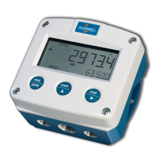
F173-A
LEVEL INDICATOR WITH LINEARISATION
AND HIGH / LOW LEVEL ALARMS
Signal input sensor: (0)4-20mA
Signal outputs: (04-20mA/ 0-10V ref. level
Alarm outputs: maximum four level alarms
Options: Intrinsically Safe, Modbus communication
F-Series - Field mounted indicators for safe and hazardous areas. More info: www.fluidwell.com/fseries
Advertisement
Table of Contents

Related Manuals for Fluidwell F Series


Summary of Contents for Fluidwell F Series
- Page 1 AND HIGH / LOW LEVEL ALARMS Signal input sensor: (0)4-20mA Signal outputs: (04-20mA/ 0-10V ref. level Alarm outputs: maximum four level alarms Options: Intrinsically Safe, Modbus communication F-Series - Field mounted indicators for safe and hazardous areas. More info: www.fluidwell.com/fseries...
-
Page 2: Safety Instructions
Intrinsically Safe applications: follow the instructions as mentioned in Chapter 5 and consult “Fluidwell F1..-..-XI - Documentation for Intrinsic Safety”. DISPOSAL At the end of its life this product should be disposed of according to local regulations regarding waste electronic equipment. -
Page 3: About The Operation Manual
Manual HF173AEN_v0501_05 © Copyright 2012 Fluidwell bv - The Netherlands. Information in this manual is subject to change without prior notice. The manufacturer is not responsible for mistakes in this material or for incidental damage caused as a direct or indirect result of the delivery, performance or use of this material. -
Page 4: Table Of Contents
Page 4 CONTENTS MANUAL Safety instructions ............................2 Disposal ..............................2 Safety rules and precautionary measures ....................... 2 About the operation manual ..........................3 Contents manual .............................. 4 Introduction ..........................5 1.1. System description of the F173-A ..................5 Operational ..........................7 2.1. -
Page 5: Introduction
Page 5 INTRODUCTION 1.1. SYSTEM DESCRIPTION OF THE F173-A Functions and features The level indicator model F173-A is a microprocessor driven instrument designed to display the linearized level and percentage as well as monitoring the level with four alarm values for a low-low, low, high and high-high level. - Page 6 Page 6 Configuration of the unit The F173-A was designed to be implemented in many types of applications. For that reason, a SETUP-level is available to configure your F173-A according to your specific requirements. SETUP includes several important features, such as Span, measurement units, signal settings etc. All setting as are stored in EEPROM memory and will not get lost in case of power break-down or empty battery.
-
Page 7: Operational
Page 7 OPERATIONAL 2.1. GENERAL The F173-A may only be operated by personnel who are authorized and trained by the operator of the facility. All instructions in this manual are to be observed. Take careful notice of the " Safety rules, instructions and precautionary measures " in the front of this manual. - Page 8 Page 8 For the Operator, the following functions are available: Display level This is the main display information of the F173-A. After selecting any other information, it will always return to this main display automatically. The contents or percentage is displayed with 17mm digits on the upper line.
-
Page 9: Configuration
Page 9 CONFIGURATION 3.1. INTRODUCTION This and the following chapters are exclusively meant for electricians and non-operators. In these, an extensive description of all software settings and hardware connections are provided. Mounting, electrical installation, start-up and maintenance of the instrument may only be carried out by trained personnel authorized by the operator of the facility. - Page 10 Page 10 Matrix structure SETUP-level: SCROLLING THROUGH SETUP-LEVEL Selection function-group and function: SETUP is divided into several function groups and functions. Each function has a unique number, which is displayed below the word "SETUP" at the bottom of the display. The number is a combination of two figures. The first figure indicates the function-group and the second figure the function.
- Page 11 Page 11 To change or a select a value or value: To change a value, use to select the digits and to increase that value. To select a setting, both and can be used. When the new value is not valid, the increase sign or decrease-sign will be displayed while you are programming.
-
Page 12: Overview Functions Setup Level
Page 12 3.2.2. OVERVIEW FUNCTIONS SETUP LEVEL SETUP FUNCTIONS AND VARIABLES LEVEL UNIT mL - L - m3 - mg - g - kg - ton - GAL - bbl - lb - cf - REV - no unit DECIMALS 0 - 1 - 2 - 3 (Ref: displayed value) SPAN 0.000001 - 999,999 unit... -
Page 13: Explanation Setup-Functions
Page 13 3.2.3. EXPLANATION SETUP-FUNCTIONS 1 - LEVEL SETUP - 11 determines the measurement unit for level. MEASUREMENT UNIT The following units can be selected: mL - L - m3 - mg - g - kg - ton - GAL - bbl - lb - cf - REV - no unit - scf - Nm3 - NL - P. -
Page 14: Alarm
Page 14 2 - ALARM With these settings, it is determined how the level will be monitored and the functionality of the transistor / relay outputs be determined. Please be aware that the alarm levels can be programmed at operator level as well. Moreover, the function be locked (setup 32). -
Page 15: Display
Page 15 3 - DISPLAY The large 17mm digits can be set to display level (SPAN) or percentage. FUNCTION After pressing “SELECT” at operator level, the other information will always be displayed as well. Important: this selection does influence the alarm values as well: if you select percentage, all alarms will have to be set as a percentage as well!! With this function it is determined if the operator can enter alarm values or ALARM SET... -
Page 16: Sensor
Page 16 5 - SENSOR The analog output signal of a sensor does mirror the actual level. This FILTER signal is measured several times a second by the F173-A. The value measured is a "snap-shot" of the real level as it will be fluctuating. With the help of this digital filter a stable and accurate reading can be obtained while the filter level can be set to a desired value. -
Page 17: Sensor (Continued)
Page 17 5 - SENSOR (CONTINUED) With this setting it is possible to calibrate the input value for 20mA as the TUNE MAX / 20MA signal from the sensor might not be exact 20.0 mA at maximum level. This function will measure the real output value at maximum level. ... -
Page 18: Linearization
Page 18 6 - LINEARIZATION The linearization function is available to correct for the tank shape, to approach the real contents of the tank at any height, beyond the general Span entered with setup 13. A maximum of fifteen linearization-positions can be entered while the interpolation will calculate any other position in-between. -
Page 19: Analog Output
Page 19 6 - LINEARIZATION (CONTINUED) The percentage is displayed at the bottom line of the display. PERCENTAGE / With value 0% the M-Factor is disabled. M-FACTOR 61 TO 6F The M-Factor is displayed at the top-line of the display. The minimum value to be entered is 0.000001 and the maximum value is 9.999999. - Page 20 Page 20 7 - ANALOG OUTPUT (CONTINUED) The initial minimum analog output value is 0/4mA or 0V. However, this TUNE MIN / 4MA value might differ slightly due to external influences such as temperature for example. The 0/4mA or 0V value can be tuned precisely with this setting.
-
Page 21: Relay Output
Page 21 8 - RELAY OUTPUT With “SETUP 2”, four alarm levels can be entered. Based on the options order, the F173-A will have 2, 3 or 4 alarm outputs. Note: If the unit is Intrinsically Safe, it will have two alarm outputs. If type OS (relay board) has been supplied, it will have four alarm outputs. -
Page 22: Installation
Page 22 INSTALLATION 4.1. GENERAL DIRECTIONS Mounting, electrical installation, start-up and maintenance of this instrument may only be carried out by trained personnel authorized by the operator of the facility. Personnel must read and understand this Operating Manual before carrying out its instructions. ... -
Page 23: Dimensions- Enclosure
Page 23 4.3. DIMENSIONS- ENCLOSURE Aluminum enclosures: 75 mm (2.95") 112 mm (4.40") 130 mm (5.12") 12mm 12mm 30mm 30mm 24mm 24mm M20 x 1,5 6 x M12 36mm 36mm 30mm 30mm M16 x 1,5 M16 x 1,5 1/2"NPT M20 x 1,5 0.12"... - Page 24 Page 24 GRP enclosures: 75 mm (2.95") 112 mm (4.40") 130 mm (5.12") HK back box: (flat bottom) 75 mm (2.95") 118 mm (4.65”) 25mm 25mm D=20mm D=20mm 12mm 12mm 30mm 30mm 24mm 24mm D=12mm D=16mm D=16mm D=20mm 36mm 36mm 0.12”...
-
Page 25: Installing The Hardware
Page 25 4.4. INSTALLING THE HARDWARE 4.4.1. INTRODUCTION Electro static discharge does inflict irreparable damage to electronics! Before installing or opening the unit, the installer has to discharge himself by touching a well-grounded object. This unit must be installed in accordance with the EMC guidelines (Electro Magnetic Compatibility). -
Page 26: Voltage Selection Sensor Supply
Page 26 4.4.2. VOLTAGE SELECTION SENSOR SUPPLY For Intrinsically Safe applications: read chapter 5. Type PB / PC / PX (AP) - battery powered and output loop-powered applications: Terminal 11 provides a limited supply voltage of 3.2 V DC. This is not suitable to power analog sensors. -
Page 27: Terminal Connectors
Page 27 4.4.3. TERMINAL CONNECTORS For Intrinsically Safe applications: read chapter 5. The following terminal connectors are available: ANALOG OUTPUT TYPE AA / AB LEVEL SENSOR POWER SUPPLY ALARM R2 ALARM R 1 AI / AP / AU ALARM R 3 INPUT TYPE A TYPE TYPE... - Page 28 Page 28 Terminal 03-04; transistor or relay output R2: This output is an alarm output according setup 82. Terminal 05-06; transistor or relay output R1: This output is an alarm output according setup 81. Type OA: An active 24V DC signal output is available with this option. Max.
- Page 29 Page 29 Type OT: A passive transistor output is available with this option. Max. driving capacity 300mA@50V DC. Terminal 07-08; basic POWER SUPPLY - type PX - output loop powered: Connect an external power supply of 8-30VDC to these terminals or a 4-20mA loop. Do connect the "-"...
- Page 30 Page 30 Type AB: An active 0-20mA signal proportional to the level is available with this option. Max. driving capacity 1000 Ohm @ 24VDC. (Requires power supply type PD / PF / PM). Type AF: For the Intrinsically Safe floating 4-20mA signal: please read Chapter 5. Type AI: An isolated 4-20mA signal proportional to the level is available with this option.
- Page 31 Page 31 Type AU: A 0-10VDC signal proportional to the level is available with this option. Max. load 10mA @ 10VDC. (Requires power supply type PD / PF / PM). Terminal 09-11: Type A – Flowmeter input (general) The F173-A requires a (0)4-20mA flowmeter signal which will be processed 4 times a second with a 14 bits accuracy.
- Page 32 Page 32 Terminal 15-16; alarm output R3: This output is an alarm output according setup 83. Type OA: An active 24V DC level alarm output is available with this option. Max. driving capacity 50mA@. (Requires power supply type PD / PF / PM). Active output - R3 INTERNAL EXTERNAL...
- Page 33 Page 33 Terminal 26-31: type CB / CH / CI / CT - communication RS232 / RS485 / TTL (option) Full serial communications and computer control in accordance with RS232 (length of cable max. 15 meters) or RS485 (length of cable max. 1200 meters) is possible. Read the Modbus communication protocol and Appendix C.
-
Page 34: Intrinsically Safe Applications
Please Note Certificates, safety values and declaration of compliance can be found in the document named: “Fluidwell F1..-..-XI - Documentation for Intrinsic Safety”. Special conditions for safe use mentioned in both the certificate and the installation instructions must be observed for the connection of power to both input and / or output circuits. -
Page 35: Terminal Connectors Intrinsically Safe Applications
Indicated labels on the back cover (below) and on the inside cover (right) show the type labels for intrinsically safe certified units. For details on usage see the separate “Fluidwell F1..-..-XI Documentation for Intrinsic Safety”. Serial number and year of production This information can be looked-up on the display: See setup function (par. - Page 36 Page 36 Explanation Intrinsically Safe options: Option AF - Intrinsically Safe floating 4-20mA analog output: A floating 4-20mA signal proportional to the level is available with this option. When the output is disabled, a 3.5mA signal will be generated. Max. driving capacity 1000 Ohm @ 30VDC. Type PD - Intrinsically Safe power supply and sensor supply - Terminal GND- 01 and 11.
-
Page 37: Configuration Examples Intrinsically Safe Applications
Page 37 5.3. CONFIGURATION EXAMPLES INTRINSICALLY SAFE APPLICATIONS Configuration example IIB /IIIC F173-A-AF-CT-OT-(PB)-(PD)-XI HAZARDOUS AREA SAFE AREA TERMINAL CONNECTORS F100-series Modbus communication type CT: TTL I.S. Certified Isolator TTL to: = max. 30 V e.g. PC RS232 = max. 250 mA RS422 = max. - Page 38 Page 38 Configuration example IIB/IIIC and IIC - F173-A-AF-(CT)-OT-PD-XI HAZARDOUS AREA SAFE AREA TERMINAL CONNECTORS F100-series Modbus communication type CT: TTL Please note: communciation type CT is allowed in IIC applications. I.S. Certified Isolator TTL to: = max. 30 V e.g.
-
Page 39: Battery Replacement Instructions
Batteries for use in safe areas have no Ex label. DO NOT EXCHANGE: Using the wrong type of battery can pose a SERIOUS RISK. For use in hazardous areas Fluidwell recommends FW-LiBAT type batteries (manufactured by Fluidwell bv) only. Battery replacement procedure Depending on the production batch, one of two visualized Intrinsically Safe certified battery types may have been installed in the unit. -
Page 40: Maintenance
Page 40 MAINTENANCE 6.1. GENERAL DIRECTIONS Mounting, electrical installation, start-up and maintenance of the instrument may only be carried out by trained personnel authorized by the operator of the facility. Personnel must read and understand this Operating Manual before carrying out its instructions. ... -
Page 41: Appendix A: Technical Specification
Page 41 APPENDIX A: TECHNICAL SPECIFICATION GENERAL Display Type High intensity reflective numeric and alphanumeric LCD, UV-resistant. Digits Seven 17mm (0.67") and eleven 8mm (0.31"). Various symbols and measuring units. Refresh rate User definable: 8 times/sec - 30 secs. Type ZB Transflective LCD with green LED backlight. - Page 42 Page 42 Sensor excitation Type PB / PC / PX 3.2V DC for pulse signals and 1.2V DC for coil pick-up. Note: This is not a real sensor supply. Only suitable for pulse sensors with a very low power consumption like coils (sine wave) and reed-switches. Type PD 1.2 - 3.2 - 8.2 - 12 and 24V DC - max.
- Page 43 Page 43 OUTPUTS Analog output Function transmitting actual temperature. Accuracy 10 bit. Error < 0.05% - update 10 times a second. Software function to calibrate the 4.00mA and 20.00mA levels precisely within set-up. Load max. 1 kOhm Type AA Active 4-20mA output (requires type OA + PD, PF or PM). Type AB Active 0-20mA output (requires type OA + PD, PF or PM).
-
Page 44: Appendix B: Problem Solving
Page 44 APPENDIX B: PROBLEM SOLVING In this appendix, several problems are included that can occur when the F173-A is going to be installed or while it is in operation. Analog output does not function properly: Check: SETUP 71 - is the function enabled? ... -
Page 45: Appendix C: Communication Variables
Page 45 APPENDIX C: COMMUNICATION VARIABLES Remarks: Below, an overview of the F173-A specific variables; other common variables are described in the standard table. All numbers are decimal numbers, unless otherwise noted. Following variables of the standard table (var00-var30) are not valid for this product and will be responded with value 1: var00, 03-05, 07,08, 16-22, 24, 26-29. - Page 46 Page 46 SENSOR filter 0….99 (63h) cut-off 0….999 steps of 0.1% (64h) calibration low 0=default (66h) (4mA) 1=calibrate 2=cal set calibration high 0=default (67h) (20mA) 1=calibrate 2=cal set ANALOG OUTPUT analog output 0=disable (70h) 1=enable minimum 0..9999999 unit, time, decimals acc. var48-50 (71h) maximum 0..9999999...
- Page 47 Page 47 LIST OF CONFIGURATION SETTINGS SETTING DEFAULT DATE : DATE : 1 - LEVEL 11 unit 12 decimals 0000000 13 span 000001 14 decimals span 15 off set 2 - ALARM 21 level zero default 22 alarm low-low 23 alarm low 24 alarm high 25 alarm high-high 26 delay alarm low-low...
- Page 48 A - OTHERS A4 password 0000 A5 tagnumber 0000000 Fluidwell bv HF173AEN_v0501_05 PO box 6 Voltaweg 23 Website: www.fluidwell.com 5460 AA Veghel 5466 AZ Veghel Find your nearest representative: www.fluidwell.com/representatives The Netherlands The Netherlands Copyright Fluidwell bv - 2012 - HF110AEN_v0501_03...
Need help?
Do you have a question about the F Series and is the answer not in the manual?
Questions and answers