Fluidwell F Series Manual
Multi-purpose monitor with high / low alarms, analog and pulse outputs, signal input sensor: 0 4-20 ma, signal outputs: 0 4-20 ma / 0-10 v ref. sensor signal or percentage, alarm outputs: maximum four level alarms, options: intrinsically safe, modbus comm
Hide thumbs
Also See for F Series:
- Manual (64 pages) ,
- User manual (60 pages) ,
- Operation manual (60 pages)
Table of Contents
Advertisement
Quick Links
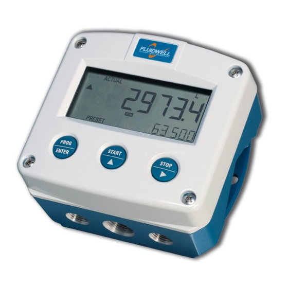
F190-A
MULTI-PURPOSE MONITOR
with high / low alarms, analog and pulse outputs
Signal input sensor: (0)4-20 mA
Signal outputs: (0)4-20 mA / 0-10 V ref. sensor signal or percentage
Alarm outputs: maximum four level alarms
Options: Intrinsically safe, Modbus communication, and backlight
F-Series - Field mounted indicators for safe and hazardous areas.
More info: www.fluidwell.com/fseries
Advertisement
Table of Contents


Need help?
Do you have a question about the F Series and is the answer not in the manual?
Questions and answers