Fluidwell F Series Manual
Loop powered
Hide thumbs
Also See for F Series:
- Manual (64 pages) ,
- User manual (60 pages) ,
- Operation manual (60 pages)

Related Manuals for Fluidwell F Series


Summary of Contents for Fluidwell F Series
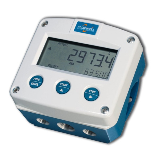
- Page 1 F490-A-PL LOOP POWERED INDICATOR Signal input sensor: 4-20mA. Options: Backlight and Intrinsic Safety F-Series - Field mounted indicators for safe and hazardous areas. More info: www.fluidwell.com/fseries...
-
Page 2: Safety Instructions
Page 2 SAFETY INSTRUCTIONS • Any responsibility is lapsed if the instructions and procedures as described in this manual are not followed. • LIFE SUPPORT APPLICATIONS: The F490-A-PL is not designed for use in life support appliances, devices, or systems where malfunction of the product can reasonably be expected to result in a personal injury. -
Page 3: About The Operation Manual
WARRANTY AND TECHNICAL SUPPORT For warranty and technical support for your Fluidwell products, visit our internet site www.fluidwell.com or contact us at support@fluidwell.com. Hardware version 4B03.01.xx Software version 03.01.4x... -
Page 4: Table Of Contents
Page 4 CONTENTS MANUAL Safety instructions ..........................2 Disposal of electronic waste ......................... 2 Safety rules and precautionary measures .................... 2 About the operation manual ......................... 3 Warranty and technical support ......................3 Contents manual ........................... 4 Introduction ..........................5 System description of the F490-A-PL ................. -
Page 5: Introduction
Page 5 INTRODUCTION SYSTEM DESCRIPTION OF THE F490-A-PL Functions and features The multi purpose indicator model F490-A-PL is a loop powered microprocessor driven instrument, designed to display process information from a 4-20mA signal, like pressure, temperature, percentage etc. This product has been designed with a focus on: •... -
Page 6: Operational
Page 6 OPERATIONAL GENERAL • The F490-A-PL may only be operated by personnel who are authorized and trained by the operator of the facility. All instructions in this manual are to be observed. • Take careful notice of the "Safety rules, instructions and precautionary measures" in the front of this manual. - Page 7 Page 7 For the Operator, the following functions are available (if activated): • Display value and measuring unit This is the main display information of the F490-A-PL. After selecting any other information, it will always return to this main display automatically. •...
-
Page 8: Configuration
Page 8 CONFIGURATION INTRODUCTION This and the following chapters are exclusively meant for electricians and non-operators. In these, an extensive description of all software settings and hardware connections are provided. • Mounting, electrical installation, start-up and maintenance of the instrument may only be carried out by trained personnel authorized by the operator of the facility. -
Page 9: Programming Sequence
Page 9 Use the control panel to navigate through SETUP-level PROG-key When a function is selected, this key is used to start the programming sequence. SELECT-key This key is used to select the next function in the list (e.g. 1 → 1.1 → 1.2 → 1). When the top of the list is reached, it will wrap around and return to the function group selection. -
Page 10: Returning To Operator-Level
Page 10 3.2.4 RETURNING TO OPERATOR-LEVEL When all settings are configured correctly, the unit can be returned to OPERATE-level. Please keep a record of all settings for later reference. Use the control panel to return to OPERATE-level PROG-key In order to return to the operator level, press the PROG-key for three seconds. When no keys are pressed for 2 minutes, SETUP-level will be left automatically. -
Page 11: Explanation Of Setup-Menu 1: Display
Page 11 3.3.1 EXPLANATION OF SETUP-MENU 1: DISPLAY 1 DISPLAY SETUP – 1.1 determines the measurement unit to be displayed. UNIT The following units can be selected: L – NL – mL – M3 – AM3 – NM3 – mg – g – Kg – TON – OZ – GAL – USGAL –... -
Page 12: Explanation Of Setup-Menu 2: Sensor
Page 12 3.3.2 EXPLANATION OF SETUP-MENU 2: SENSOR 2 SENSOR FORMULA The F490-A-PL can process the 4-20mA signal in two ways: ▪ V = S x I Interpolation - the signal is processed linear: √ ▪ V = S Square root - for differential pressure: where: V = Value: the calculated value S = Span: the value at maximum signal (Span). -
Page 13: Explanation Of Setup-Menu 3: Others
Page 13 TUNE MAX / With this setting it is possible to calibrate the input value for 20mA as the 20MA signal from the sensor might not be exact 20.0 mA at maximum signal. ▪ Warning: be very sure that the offered signal is correct before the calibration is executed as this function has major influences on the accuracy of the system! After pressing PROG, three settings can be selected:... -
Page 14: Installation
Page 14 INSTALLATION GENERAL DIRECTIONS • Mounting, electrical installation, start-up and maintenance of this instrument may only be carried out by trained personnel authorized by the operator of the facility. Personnel must read and understand this Operating Manual before carrying out its instructions. •... -
Page 15: Handling The F-Series Enclosure
Page 15 HANDLING THE F-SERIES ENCLOSURE 4.3.1 IDENTIFICATION For Intrinsically Safe applications: Installation and identification labels are shown in chapter 5. Identification label To identify your F4-Series device, all field mount enclosures have a weatherproof identification label placed on the outside of the unit. Fig. -
Page 16: Opening / Removing The Cover
Page 16 4.3.2 OPENING / REMOVING THE COVER To open the F-Series enclosure, the front cover needs to be removed. Please follow this procedure: 1. If necessary, clean the enclosure with an anti-static cloth made damp with a mild soap solution. Wait for the enclosure to dry before opening. -
Page 17: Mechanical Installation
Page 17 MECHANICAL INSTALLATION DIMENSIONS – ALUMINUM AND STAINLESS STEEL ENCLOSURES 4.4.1 • → When ordering stainless steel enclosures, the code “H_” turns to “HS_”, e.g. HA HSA). • Aluminum enclosures are available with a 15 mm, 0.6” deeper rear cover (code turns to HB_). 75 mm (2.95") 112 mm (4.40") 130 mm (5.12") -
Page 18: Dimensions - Non-Metallic Enclosures
Page 18 DIMENSIONS – NON-METALLIC ENCLOSURES 4.4.2 75 mm (2.95") 112 mm (4.40") 130 mm (5.12") HK back box: (flat bottom) 75 mm (2.95") 118 mm (4.65”) 25mm 25mm D=20mm D=20mm 12mm 12mm 30mm 30mm 24mm 24mm D=12mm D=16mm D=16mm D=20mm 36mm 36mm... -
Page 19: Mounting
Page 19 4.4.3 MOUNTING • When installed in an aluminum enclosure and a potentially explosive atmosphere requiring apparatus of equipment protection level Ga and Da, the unit must be installed such that, even in the event of rare incidents, an ignition source due to impact or friction sparks between the enclosure and iron/steel is excluded. -
Page 20: Electrical Installation
Page 20 4.5. ELECTRICAL INSTALLATION • Electrostatic discharge (ESD) does inflict irreparable damage to electronics! Before installing or opening the F490-A-PL, the installer has to discharge himself by touching a well-grounded object. • For reasons of ESD and safety, always ground the metal enclosure properly as indicated. It is the responsibility of the installer to install, connect and test the Protective Earth connections in accordance with the (inter)national Rules and Regulations. -
Page 21: Field Wiring Connections
Page 21 4.5.3 FIELD WIRING CONNECTIONS • Do ground the aluminum enclosure properly as indicated in paragraph 4.5.2. It is the responsibility of the installer to install, connect and test the ground connections in accordance with the local and (inter)national Rules and Regulations. •... -
Page 22: Terminal 4-5: 4-20Ma Signal Input And Power Supply - Type Pl
Page 22 4.6.3 TERMINAL 4-5: 4-20MA SIGNAL INPUT AND POWER SUPPLY - TYPE PL The F490-A-PL requires a 4-20mA signal that will be processed 4 times. With Type PL, the unit will be powered from the 4-20mA input signal. The input circuit is isolated from the backlight circuit on terminals 9 and 10. With the use of the signal links between terminal 2 and 3 and between terminal 6 and 7, it is possible to easily connect the signal wires and cable screens of two separate cables. -
Page 23: Intrinsically Safe Applications
Page 23 INTRINSICALLY SAFE APPLICATIONS IDENTIFICATION Identification label To identify your F4-Series device, all field mount enclosures have a weatherproof identification label placed on the outside of the unit. Fig. 13: Identification – Example of F4-Series identification label (intrinsic safety) Installation label A second label is located on the inside and shows additional installation data. -
Page 24: Electrical Installation In Hazardous Area
Page 24 ELECTRICAL INSTALLATION IN HAZARDOUS AREA The following paragraph shows general information regarding the installation of the F490-A-PL-XI in hazardous area. This is followed by paragraphs outlining specific information regarding each individual certificate and their specific installation demands. 5.2.1 GENERAL INFORMATION AND INSTRUCTIONS Cautions •... -
Page 25: Installations Based On Atex Or Iecex Certificate
Page 25 5.2.2 INSTALLATIONS BASED ON ATEX OR IECEX CERTIFICATE Installation instructions • For installation under ATEX directive: this Intrinsically Safe device must be installed in accordance with ATEX directive 2014/34/EU and product certificate KEMA 03ATEX1075 X. • For installation under IECEx scheme: this Intrinsically Safe device must be installed in accordance with product certificate IECEx DEK 08.0007X. - Page 26 Page 26 For Intrinsically Safe installations under ATEX and IECEx Scheme, the following safety parameters apply: Input circuit (terminals 4 and 5): 0 nF 0 mH Backlight circuit (terminals 9 and 10): 0 nF mA (resistively limited) 0 mH = 0.96 The backlight circuit is separated from the input circuit.
-
Page 27: Installations Based On Csa Certificate
Page 27 5.2.3 INSTALLATIONS BASED ON CSA CERTIFICATE CSA certificate Installation instructions • For installation in the US: this Intrinsically Safe device must be installed in accordance with the National Electrical Code, NFPA 70, Article 504 and ANSI/ISA-RP 12.6 and product certificate CSA.14.70002331. - Page 28 Page 28 Fig. 16: Terminal connections CSA / Control Drawing CD1104.11 FW-F490-A-PL_v0504_06_EN.docx...
-
Page 29: Maintenance
Page 29 MAINTENANCE GENERAL DIRECTIONS • Mounting, electrical installation, start-up and maintenance of the instrument may only be carried out by trained personnel authorized by the operator of the facility. Personnel must read and understand this Operating Manual before carrying out its instructions. •... -
Page 30: Appendix A: Technical Specification
Page 30 APPENDIX A: TECHNICAL SPECIFICATION GENERAL Display Type High intensity reflective numeric and alphanumeric LCD, UV-resistant. 90x40mm (3.5”x1.6”) Digits 5 ½ 26mm (1") and eleven 8mm (0.31"). Various symbols and measuring units. Piegraph 10 segment range indication in relation to its measuring range 0-100% Refresh rate 1 times/sec. - Page 31 Page 31 Data protection Type EEPROM backup of all setting. Data retention at least 10 years. Pass code Configuration settings can be pass code protected. Hazardous area (option) Intrinsically safe ATEX approval: KEMA 03ATEX1075 X Type XI I M1 Ex ia I Ma II 1 G Ex ia IIC T4 Ga II 1 D...
-
Page 32: Appendix B: Problem Solving
Page 32 APPENDIX B: PROBLEM SOLVING In this appendix, several problems are included that can occur when the F490-A-PL is going to be installed or while it is in operation. Display is "0 / zero" while a higher signal is available: Check: ▪... -
Page 33: Appendix C: Declaration Of Conformity
Page 33 APPENDIX C: DECLARATION OF CONFORMITY eghel, February 2022 e, Fluidwell , declare under our sole responsibility that the D4 and F4 Series indicators are designed and will operate conform the following applicable European Directives and armonised Standards, when installed and operated according to the related manuals... -
Page 34: Index Of This Manual
Page 34 INDEX OF THIS MANUAL actual settings ..........36 measuring unit ..........11 backlight ............22 model ............13 calibrate ............12 operational ........6, 8, 14, 29 Configuration ..........8 Operator level ..........6 contents ............4 pass code ..........13, 32 decimals ............ - Page 35 Page 35 Notes: FW-F490-A-PL_v0504_06_EN.docx...
- Page 36 3.4 pass code 0000 3.5 tagnumber 0000000 Fluidwell bv FW-F490-A-PL_v0504_06_EN.docx PO box 6 Voltaweg 23 Website: www.fluidwell.com 5460 AA Veghel 5466 AZ Veghel Find your nearest representative: www.fluidwell.com/representatives The Netherlands The Netherlands Copyright Fluidwell bv - © 2022 - FW-F490-A-PL_v0504_06_EN.docx...
Need help?
Do you have a question about the F Series and is the answer not in the manual?
Questions and answers