Fluidwell F Series Manual
Flow rate indicator/totalizer with analog and pulse outputs
Hide thumbs
Also See for F Series:
- Manual (64 pages) ,
- User manual (60 pages) ,
- Operation manual (60 pages)
Table of Contents
Advertisement
Quick Links
F110-A
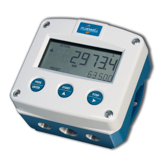
FLOW RATE INDICATOR / TOTALIZER
with analog and pulse outputs
Signal input flowmeter: (0)4-20mA
Signal outputs: (0)4-20mA / 0-10V ref. flow rate and pulse ref. total.
Options: Intrinsically safe, Modbus communication, external reset and
backlight.
F-Series - Field mounted indicators for safe and hazardous areas.
More info: www.fluidwell.com/fseries
Advertisement
Table of Contents

Related Manuals for Fluidwell F Series


Summary of Contents for Fluidwell F Series
- Page 1 Signal input flowmeter: (0)4-20mA Signal outputs: (0)4-20mA / 0-10V ref. flow rate and pulse ref. total. Options: Intrinsically safe, Modbus communication, external reset and backlight. F-Series - Field mounted indicators for safe and hazardous areas. More info: www.fluidwell.com/fseries...
-
Page 2: Safety Instructions
▪ Intrinsically safe applications: follow the instructions as mentioned in Chapter 5 and consult “Fluidwell F1..-..-XI - Documentation for Intrinsic safety”. DISPOSAL OF ELECTRONIC WASTE • The WEEE Directive requires the recycling of disposed electrical and electronic equipment in the European Union. -
Page 3: About The Manual
WARRANTY AND TECHNICAL SUPPORT For warranty and technical support for your Fluidwell products, visit our internet site www.fluidwell.com or contact us at support@fluidwell.com. Hardware version : 03.01.xx Software version : 03.03.xx... -
Page 4: Table Of Contents
Page 4 CONTENTS MANUAL Safety instructions ..........................2 Disposal of electronic waste ......................2 Safety rules and precautionary measures ..................2 About the manual ..........................3 Warranty and technical support ......................3 Contents manual ..........................4 Introduction ....................... 5 1.1. System description ...................... -
Page 5: Introduction
Page 5 INTRODUCTION 1.1. SYSTEM DESCRIPTION Functions and features The flow rate / totalizer model F110-A is a microprocessor driven instrument designed to display the flow rate, the total and the accumulated total. This product has been designed with a focus on: ▪... -
Page 6: Operational
Page 6 Configuration The F110-A is designed for use in many types of applications. For that reason, a setup menu is available to program the F110-A according to your specific requirements. The setup includes several important features, such as span, engineering units, signal selection, power management (to extend battery life-time), etc. -
Page 7: Operator Information And Functions
Page 7 2.2. OPERATOR INFORMATION AND FUNCTIONS In general, the F110-A operates in the operator mode. The shown information depends on the settings which are made in the setup menu. The signal from the connected sensor is processed by the F110-A in the background, independent from R U N the selected display refresh rate. -
Page 8: Configuration
Page 8 CONFIGURATION This and the following chapters are exclusively meant for electricians and non-operators. In these, an extensive description of all software settings and hardware connections are provided. • Mounting, electrical installation, start-up and maintenance of this device may only be carried out by trained persons authorized by the operator of the facility. - Page 9 Page 9 The SELECT/▲ key and the CLEAR/► key are used for navigation. The explanation assumes that you are in the submenu TOTAL. When you are: • in the first setting and you navigate to the previous setting, the F110-A goes back to the related main menu.
-
Page 10: Setup Menu - Settings
Page 10 3.1.1. SETUP MENU - SETTINGS TOTAL unit L; m ; kg; lb; GAL; USGAL; bbl; no unit decimals 0000000; 111111.1; 22222.22; 3333.333 span 0.000001 - 999,999 decs span 0 - 6 FLOW RATE unit mL; L; m ; mg; g; kg; ton; gal; bbl; lb; cf; rev; - - - - (no unit); scf; ;... -
Page 11: Explanation Of Setup-Menu 1 - Total
Page 11 3.1.2. EXPLANATION OF SETUP-MENU 1 - TOTAL This setting is used to select the engineering unit for the indication of the total, the UNIT accumulated total and the pulse output. When you change the engineering unit , you must recalculate and reprogram the span for the (accumulated) total. -
Page 12: Explanation Of Setup-Menu 3 - Display
Page 12 SPAN With the span, the flowmeter signal is converted to a quantity. The span for flowrate is determined on the basis of the selected measurement unit and time unit at 20mA (or maximum signal). Enter the span in whole numbers (decimals are set with SETUP 25). -
Page 13: Explanation Of Setup-Menu 5 - Flowmeter
Page 13 3.1.6. EXPLANATION OF SETUP-MENU 5 - FLOWMETER FORMULA The F110-A can process the (0)4-20mA signal in two ways: Interpolation or Square root: • Interpolation: the signal is processed linear: R = S x I • Square root: for differential pressure: R = S √... -
Page 14: Explanation Of Setup Menu 6 - Analog
Page 14 3.1.7. EXPLANATION OF SETUP MENU 6 - ANALOG A linear 4-20mA signal (option AB: 0-20mA or option AU: 0-10V) output signal is generated that represents the flow rate. The settings for the flow rate influence the analog output directly. The relationship between the flow rate and the analog output is set with the following settings. -
Page 15: Explanation Of Setup Menu 7 - Pulse
This product is designed for the connection to a communication network. Products with a communication option do not include cyber security functions. Fluidwell cannot take any responsibility for the cyber security, omissions or errors in the communication safety. To maintain a... -
Page 16: Installation
Page 16 INSTALLATION 4.1. GENERAL DIRECTIONS • Mounting, electrical installation, start-up and maintenance of this device may only be carried out by trained persons authorized by the operator of the facility. Persons must read and understand this manual before carrying out its instructions. •... -
Page 17: Dimensions- Enclosure
Page 17 4.3. DIMENSIONS- ENCLOSURE Aluminum and stainless enclosures (where “H” turns to “HS” for stainless, e.g. HA → HSA): 75 mm (2.95") 112 mm (4.40") 130 mm (5.12") 12mm 12mm 30mm 30mm 24mm 24mm M20 x 1,5 6 x M12 36mm 36mm 25mm... - Page 18 Page 18 75 mm (2.95") 112 mm (4.40") 130 mm (5.12") HK back box: (flat bottom) 75 mm (2.95") 118 mm (4.65”) 25mm 25mm D=20mm D=20mm 12mm 12mm 30mm 30mm 24mm 24mm D=12mm D=16mm D=16mm D=20mm 36mm 36mm 0.12” 0.12” D=22mm (0.866") 3x D=22mm (0.866”) 29.1 mm (1.15”)
-
Page 19: Installing The Hardware
The wire screens shall be terminated at one side to prevent wire loops. Inside of the Fluidwell unit, the different common ground terminals are connected to each other. It is advised, as illustrated, to terminate the wire screens in the vicinity of the sensor and to insulated the wire screen with a shrink tube at the Fluidwell unit side. -
Page 20: Protective Earth (Pe) Connections
Page 20 4.4.2. PROTECTIVE EARTH (PE) CONNECTIONS Inside the unit, different types of bonding and earthing are used. The common ground is mostly used for termination of the wire shields; the Protective Earth (PE) is used for electrical safety. For externally powered installations, route the Protective Earth (PE) grounding conductor into the enclosure together with the incoming power conductors. -
Page 21: Aluminum Enclosure - Field Mounted
Do not use the terminal 00 to connect the protective earth wire, the 00 and the common ground terminals are internally connected. Be careful, to prevent damage to equipment when you connect different power supplies (sensor, PLC, etc.). Inside the Fluidwell display, the common grounds are internally connected to each other. -
Page 22: Plastic (Grp) Enclosure
Page 22 4.4.5. PLASTIC (GRP) ENCLOSURE The PE connection The F110-A in a GRP enclosure meets the requirements of class 2 (double insulated). Therefore the incoming PE wire is terminated with an insulating end cap. Type PM (110-230V AC) Type OR (8-24V AC) Type OR (8-30V DC) FW_F110A_v1901_02_EN.docx... -
Page 23: Terminal Connectors
Page 23 4.4.6. TERMINAL CONNECTORS For Intrinsically safe applications: read chapter 5. Refer to Appendix A: Technical Specification Fig. 8: Overview of terminal connectors - Standard configuration and options 4.4.7. SENSOR SUPPLY For type PB/PC; PX; AP: There is no real sensor supply out available. Only a limited power supply is available. - Page 24 Page 24 Set the sensor supply 1. Make the F110-A safe. If applicable, mind the battery power. 2. Open the F110-A and carefully remove the cable-connectors and the protective cover. 3. Find and set the switches and select the V as required.
- Page 25 Page 25 Type OR: A mechanical relay output is available with this option. Max. switch power 240V 0.5A per output. (Requires power supply type PF / PM). Be sure that the output frequency does not exceed 5Hz, else the relay life time will be reduced significantly.
- Page 26 Page 26 Type AB: An active 0-20mA signal proportional to the flow rate is available with this option. Max. driving capacity 1000 Ohm @ 24VDC. (Requires power supply type PD / PF / PM). Fig. 14: Terminal connections - Active 0-20mA analog output (typical) Type AF: For the Intrinsically safe floating 4-20mA signal: please read Chapter 5.
- Page 27 Page 27 Type AU: A 0-10VDC signal proportional to the flow rate is available with this option. Max. load 10mA @ 10VDC. (Requires power supply type PD / PF / PM). Fig. 17: Terminal connections - Active 0-10V analog output (typical) Terminal 09-11: Type A –...
- Page 28 Page 28 Terminal 12-13: Type IB – external reset (option): With this function the total can be reset to zero with an external switch. The Total resets only when the switch opens. When a Normally Closed (NC) contact is used, the local clear total function is disabled and a clear total is only possible with the external reset command.
-
Page 29: Intrinsically Safe Applications
Please note • Certificates, safety values, control drawing and declaration of conformity can be found in the document named: “Fluidwell F1..-..-XI - Documentation for Intrinsic safety”. • When installing this device in hazardous areas, the wiring and installation must comply with the appropriate installation standards for your industry. - Page 30 Page 30 Serial number and year of production This information can be looked-up in the setup menu: Others. Fig. 21: Example serial number (typical) Label information pulse input type – F1xx-..-..-XI (inside and outside the enclosure) Fig. 22: Label information - Intrinsically safe application (typical) FW_F110A_v1901_02_EN.docx...
-
Page 31: Terminal Connectors Intrinsically Safe Applications
Page 31 5.2. TERMINAL CONNECTORS INTRINSICALLY SAFE APPLICATIONS The unit is classified as group IIB/IIIC by default Classification of the unit as group IIC is only possible under the following conditions: The indicator is either supplied by • the internal supply (type PC); •... - Page 32 Page 32 Explanation Intrinsically safe options: Type AF - Intrinsically safe floating 4-20mA analog output - Terminal 7-8: A floating 4-20mA signal proportional to the flow rate is available with this option. When the output is disabled, a 3.5mA signal will be generated. Max. driving capacity 1000 Ohm @ 30V DC. Fig.
-
Page 33: Configuration Examples Intrinsically Safe Applications
Page 33 5.3. CONFIGURATION EXAMPLES INTRINSICALLY SAFE APPLICATIONS Fig. 26: F110-A-AF-CT-IB-OT-(PC)-(PD)-XI - Battery powered - IIB/IIC – IIIC FW_F110A_v1901_02_EN.docx... - Page 34 Page 34 Fig. 27: F110-A-AF-(CT)-IB-OT-PD-XI - External power supply - IIB/IIC – IIIC FW_F110A_v1901_02_EN.docx...
-
Page 35: Battery Replacement Instructions
Page 35 BATTERY REPLACEMENT INSTRUCTIONS 5.4.1. SAFETY INSTRUCTIONS • Handle the battery with care. A mistreated battery can become unsafe. Unsafe batteries can cause (serious) injury to persons. • Only use batteries which are certified for use in hazardous areas. The use of standard batteries in hazardous area's is not safe and prohibited. -
Page 36: Maintenance
Repairs should only be carried out by the manufacturer or his authorized agent. 6.3. REPAIR POLICY If you have any problem with your Fluidwell product and you wish to repair it, please follow the procedure below: a. Obtain a Return Material Authorization (RMA) from your supplier or distributor Together with the RMA, you need to complete a repair form to submit detailed information about the problem. -
Page 37: Appendix A: Technical Specification
Page 37 APPENDIX A: TECHNICAL SPECIFICATION GENERAL Display Type High intensity reflective numeric and alphanumeric LCD, UV-resistant. Digits Seven 17mm (0.67") and eleven 8mm (0.31"). Various symbols and measuring units. Refresh rate User definable: 8 times/sec - 30 secs. Type ZB LCD with LED backlight. - Page 38 Page 38 Sensor excitation Type PB / PC / PX 3V DC for low power pulse signals and 1.2V DC for coil pick-up. Type PD 1.2; 3; 8.2; 12; 24V DC - max. 50mA@24V DC Type PD-XI Intrinsically ally safe: Pulse signals: 1.2; 3; 8.2 - max. 7mA@8.2V DC. Type PF / PM 1.2;...
- Page 39 Page 39 Communication option Protocol bus-rtu; bus-asc Speed 1200; 2400; 4800; 9600 Addressing 1 - 247 Type CB RS232 Type CH RS485 2-wire Type CI RS485 4-wire Type CT TTL Intrinsically safe communication. Type CX no communication. OPERATIONAL Operator functions Shown functions •...
-
Page 40: Appendix B: Problem Solving
Page 40 APPENDIX B: PROBLEM SOLVING In this appendix, several problems are included that can occur when the F110-A is going to be installed or while it is in operation. Analog output does not function properly: Check: ▪ is the analog output enabled? ▪... -
Page 41: Appendix C: Communication Variables
Page 41 APPENDIX C: COMMUNICATION VARIABLES GENERAL The product is fitted with the Modbus communication protocol and can be equipped with various physical interfaces like RS485 and RS232 (please see device datasheet for available options). The tables below show the various variables that can be accessed through the communication. Currently, the function codes supported are: •... - Page 42 Page 42 Setup variables REGISTER VARIABLE TYPE VALUE / REMARKS ADDRESS TOTAL REGISTERS [d] 32 40033 unit uint16 0=none 3=kg 6= US GAL [h] 0x020 4= lb 7=bbl 2= m 5=gal [d] 33 40034 decimals uint16 0…3 [h] 0x021 [d] 34 40035 span uint32 1...9999999...
- Page 43 Page 43 REGISTER VARIABLE TYPE VALUE / REMARKS ADDRESS ANALOG OUTPUT REGISTERS [d] 112 40113 analog output uint16 0=disable 1=enable [h] 0x070 [d] 113 40114 minimum rate uint32 0…9999999 [h] 0x071 Representation: unit, time, decimals depending on variables 48, 49, 50 [d] 116 40117 maximum rate...
-
Page 44: Appendix D: Declaration Of Conformity
Page 44 APPENDIX D: DECLARATION OF CONFORMITY FW_F110A_v1901_02_EN.docx... -
Page 45: Index Of This Manual
Page 45 INDEX OF THIS MANUAL accumulated Total ......... 7 Flowrate ............7 actual settings ..........47 Installation ........... 16 analog Intrinsic safety ........29, 31 floating output........... 32 Intrinsically Safe options ......32 flowrate min..........14 IP classification ..........16 intrinsically safe output. - Page 46 Page 46 OTES …………………………………………………………………………………………………………………… …………………………………………………………………………………………………………………… …………………………………………………………………………………………………………………… …………………………………………………………………………………………………………………… …………………………………………………………………………………………………………………… …………………………………………………………………………………………………………………… …………………………………………………………………………………………………………………… …………………………………………………………………………………………………………………… …………………………………………………………………………………………………………………… …………………………………………………………………………………………………………………… …………………………………………………………………………………………………………………… …………………………………………………………………………………………………………………… …………………………………………………………………………………………………………………… …………………………………………………………………………………………………………………… …………………………………………………………………………………………………………………… …………………………………………………………………………………………………………………… …………………………………………………………………………………………………………………… …………………………………………………………………………………………………………………… …………………………………………………………………………………………………………………… …………………………………………………………………………………………………………………… …………………………………………………………………………………………………………………… …………………………………………………………………………………………………………………… …………………………………………………………………………………………………………………… …………………………………………………………………………………………………………………… …………………………………………………………………………………………………………………… …………………………………………………………………………………………………………………… …………………………………………………………………………………………………………………… …………………………………………………………………………………………………………………… …………………………………………………………………………………………………………………… …………………………………………………………………………………………………………………… …………………………………………………………………………………………………………………… …………………………………………………………………………………………………………………… FW_F110A_v1901_02_EN.docx...
- Page 47 Page 47 LIST OF CONFIGURATION SETTINGS SETTING DEFAULT DATE : DATE : 1 - TOTAL Enter your settings here 11 unit 12 decimals 0000000 13 span /sec /sec 001600 /sec 14 decs span 2 - FLOW RATE 21 unit 22 time unit /sec 23 decimals 0000000...
- Page 48 Page 48 Fluidwell B.V. FW_F110A_v1901_02_EN.docx PO box 6 Voltaweg 23 Website: www.fluidwell.com 5460 AA Veghel 5466 AZ Veghel Find your nearest representative: www.fluidwell.com/representatives the Netherlands the Netherlands © 2021 Fluidwell B.V.: FW_F110A_v1901_02_EN.docx...
Need help?
Do you have a question about the F Series and is the answer not in the manual?
Questions and answers