Fluidwell F Series Manual
Multi-purpose indicator input loop powered
Hide thumbs
Also See for F Series:
- Manual (64 pages) ,
- User manual (60 pages) ,
- Operation manual (60 pages)

Related Manuals for Fluidwell F Series


Summary of Contents for Fluidwell F Series
- Page 1 F090-A-PL MULTI-PURPOSE INDICATOR INPUT LOOP POWERED Signal input sensor: 4-20mA Options: Intrinsically Safe F-Series - Field mounted indicators for safe and hazardous areas. More info: www.fluidwell.com/fseries...
-
Page 2: Safety Instructions
Page 2 SAFETY INSTRUCTIONS • Any responsibility is lapsed if the instructions and procedures as described in this manual are not followed. • LIFE SUPPORT APPLICATIONS: The F090-A-PL is not designed for use in life support appliances, devices, or systems where malfunction of the product can reasonably be expected to result in a personal injury. -
Page 3: About The Manual
WARRANTY AND TECHNICAL SUPPORT For warranty and technical support for your Fluidwell products, visit our internet site www.fluidwell.com or contact us at support@fluidwell.com. Hardware version : 03.03.xx Software version : 03.03.xx... -
Page 4: Table Of Contents
Page 4 CONTENTS MANUAL SAFETY INSTRUCTIONS........................2 DISPOSAL OF ELECTRONIC WASTE ....................2 SAFETY RULES AND PRECAUTIONARY MEASURES ..............2 ABOUT THE MANUAL ........................3 WARRANTY AND TECHNICAL SUPPORT ..................3 CONTENTS MANUAL ......................... 4 INTRODUCTION ........................6 System description of the F090-A-PL ..................6 OPERATIONAL ........................ - Page 5 Page 5 TECHNICAL SPECIFICATION ................. 33 PROBLEM SOLVING ....................35 DECLARATION OF CONFORMITY ................. 36 INDEX OF THIS MANUAL........................37 LIST OF FIGURES ..........................38 FW-F090-A-PL-M_v0404_01_EN.docx...
-
Page 6: Introduction
Page 6 1 INTRODUCTION SYSTEM DESCRIPTION OF THE F090-A-PL Functions and features The multi-purpose indicator model F090-A-PL is a microprocessor driven instrument designed to display the actual process value, such as level, temperature, flow, pressure etc. This product has been designed with a focus on: ▪... -
Page 7: Operational
Page 7 2 OPERATIONAL GENERAL INFORMATION This chapter describes the daily use of the F090-A-PL. This instruction is meant for users / operators. • The F090-A-PL may only be operated by personnel who are authorized and trained by the operator of the facility. All instructions in this manual are to be observed •... - Page 8 Page 8 • Display actual mA value After pressing SELECT, the actual input current (mA) will be displayed. • Display 0% / 100% value After pressing SELECT a few times, the 0% value (=4mA) and 100% value (=20mA) will be displayed.
-
Page 9: Configuration
Page 9 3 CONFIGURATION INTRODUCTION This and the following chapters are exclusively meant for electricians and non-operators. In these, an extensive description of all software settings and hardware connections are provided. • Mounting, electrical installation, start-up and maintenance of the instrument may only be carried out by trained personnel authorized by the operator of the facility. -
Page 10: Programming Sequence
Page 10 Use the control panel to navigate through SETUP-level PROG-key When a function is selected, this key is used to start the programming sequence. When only a function group is selected (and no function), this key is used to scroll back a function group (e.g. -
Page 11: Returning To Operator-Level
Page 11 Step 2b: Changing the selected item in a list SELECT-key This key is used to select the next item in the list (e.g. Disable → Enable). At the end of the list, the selection will wrap around to the first selection. CLEAR-key This key is used to select the previous item in the list (e.g. -
Page 12: Configuration Settings
Page 12 CONFIGURATION SETTINGS All settings of the F090-A-PL can be set via the control panel. The following paragraphs give a detailed description of each setting. 3.3.1 OVERVIEW FUNCTIONS SETUP LEVEL SETUP FUNCTIONS AND VARIABLES DISPLAY UNIT mL - L – nL - M3 - nM3 - mg - g - kg - ton - gal - sgal - igal - lb - bbl - cf - scf - p - rev - °C - °F - °K - % - m - mm - cm - mtr - inch - ft - psi - mbar - bar - barg - mmwk - mmwc - cmwk - cmwc - mwk - mwc - inwc - ftwc - Ph - mV - no unit. -
Page 13: Explanation Of Setup-Menu 2 - Backlight
Page 13 DECIMALS This setting determines for displayed process value the number of digits following the decimal point. The following can be selected: 00000 - 1111.1 - 222.22 - 33.333 - 4.4444 - .55555 OFFSET The indicator needs to know the actual process value at minimum signal. -
Page 14: Explanation Of Setup-Menu 3 - Sensor
Page 14 3.3.4 EXPLANATION OF SETUP-MENU 3 - SENSOR SETUP FUNCTIONS AND VARIABLES SENSOR FORMULA The F090-A-PL can process the 4-20mA signal in two ways: ▪ Interpolation: the signal is processed linear V = S x I ▪ Square root: for differential pressure √... -
Page 15: Explanation Of Setup-Menu 4 - Others
Page 15 CALIBRATE HI - 20mA With this setting it is possible to calibrate the input value for 20mA as the signal from the sensor might not be exact 20.0mA at maximum process value (offset + span). Be very sure that the offered signal is correct before calibration is executed, as this has major influence on the accuracy of the system After pressing PROG, three settings can be selected: ▪... -
Page 16: Installation
Page 16 4 INSTALLATION GENERAL DIRECTIONS • Mounting, electrical installation, start-up and maintenance of this instrument may only be carried out by trained personnel authorized by the operator of the facility. Personnel must read and understand this Operating Manual before carrying out its instructions. •... -
Page 17: Handling The F-Series Enclosure
Page 17 HANDLING THE F-SERIES ENCLOSURE 4.3.1 IDENTIFICATION The F0-Series can be supplied as suitable for Safe Area or Hazardous Area. Suitability for Intrinsic Safety is indicated in the model code by Type XI (e.g. F090-A-XI). For Intrinsically Safe applications: Installation and identification labels are shown in chapter 5. Identification label To identify your F0-Series device, all field mount enclosures have a weatherproof identification label placed on the outside of the unit. -
Page 18: Opening / Removing The Cover
Page 18 Serial number and year of production The serial number can be reviewed on the identification label or in SETUP-menu Others. The production date is either shown separately on the label or indicated by the first 4 digits of the serial number representing year and week number (YYWW). -
Page 19: Mechanical Installation
Page 19 MECHANICAL INSTALLATION DIMENSIONS – ALUMINUM AND STAINLESS STEEL ENCLOSURES 4.4.1 • → When ordering stainless steel enclosures, insert S after H, e.g. HA HSA). • Aluminium enclosures are available with a 15 mm/0.6” deeper rear cover (insert B after H: HBx). -
Page 20: Dimensions - Non-Metallic Enclosures
Page 20 DIMENSIONS – NON-METALLIC ENCLOSURES 4.4.2 75 mm (2.95") 112 mm (4.40") 130 mm (5.12") HK back box: (flat bottom) 75 mm (2.95") 118 mm (4.65”) 25mm 25mm D=20mm D=20mm 12mm 12mm 30mm 30mm 24mm 24mm D=12mm D=16mm D=16mm D=20mm 36mm 36mm... -
Page 21: Mounting
Page 21 4.4.3 MOUNTING The enclosure can be installed by itself or with the aid of a mounting plate in the configurations shown below. When the unit is installed on a wall or onto a meter, please use components and installation techniques that are suitable for the used materials. -
Page 22: Electrical Installation
The wire screens shall be terminated at one side to prevent wire loops. Inside of the Fluidwell unit, the different common ground terminals are connected to each other. It is advised, as illustrated, to terminate the wire screens in the vicinity of the sensor and to insulated the wire screen with a shrink tube at the Fluidwell unit side. -
Page 23: Field Wiring Connections
Inside of the Fluidwell unit, the various common ground terminals are connected to each other. It is advised to terminate the wire screens in the vicinity of the sensor and to insulate the wire screen with a shrink tube at the F090-A-PL side. -
Page 24: Power Supply Wiring
Page 24 4.5.4 POWER SUPPLY WIRING The F090-A-PL is powered directly from the 4-20mA signal loop. Note that the optional backlight (type ZL) only works with an external power supply. TERMINAL CONNECTORS SAFE AREA APPLICATIONS Take careful notice of all safety and precautionary measures indicated in paragraph 4.5: Electrical Installation and review paragraph 4.5.3 and 4.5.4 before applying any field or power supply wiring. -
Page 25: Terminal 9-10: Power Supply Backlight - Type Zb (Option)
Page 25 4.6.2 TERMINAL 9-10: POWER SUPPLY BACKLIGHT - TYPE ZB (OPTION) To power the backlight, a voltage in the range 20-30V DC has to be connected. Maximum current 30mA. Connect the "-" to terminal 9 and the "+" to terminal 10. Fig. -
Page 26: Intrinsically Safe Applications
Page 26 5 INTRINSICALLY SAFE APPLICATIONS IDENTIFICATION The F0-Series can be supplied as suitable for Safe Area or Hazardous Area. Suitability for Intrinsic Safety is indicated in the model code by Type XI (e.g. F090-A-XI). If Type XI is not indicated your device is not suitable for Intrinsically Safe applications! Identification label To identify your F0-Series device, all field mount enclosures have a weatherproof identification label placed on the outside of the unit. -
Page 27: Electrical Installation In Hazardous Area
Page 27 ELECTRICAL INSTALLATION IN HAZARDOUS AREA 5.2.1 GENERAL INFORMATION AND INSTRUCTIONS Cautions • Mounting, electrical installation, start-up and maintenance of this device may only be carried out by trained persons authorized by the operator of the facility. Persons must read and understand this manual before carrying out its instructions. -
Page 28: Electrical Data - Control Drawing
The cable parameters are determined by the parameters of the system into which the F0-Series General Purpose Indicators is connected. Only certified Intrinsically Safe Fluidwell battery type FW-LiBat-0xx may be used and replaced in hazardous area. The entity parameters for F0-Series General Purpose Indicators, model F0xx-A-PL-XI, are as follows: Terminals 1 and 2 –... -
Page 29: Installations Based On Atex Or Iecex Certificate
Page 29 5.2.4 INSTALLATIONS BASED ON ATEX OR IECEX CERTIFICATE Installation instructions • For installation under ATEX directive: this Intrinsically Safe device must be installed in accordance with ATEX directive 2014/34/EU and product certificate KEMA 03ATEX1168 X. • For installation under IECEx scheme: this Intrinsically Safe device must be installed in accordance with product certificate IECEx DEK 08.0006X. -
Page 30: Electrical Data - Annex 1
Page 30 ELECTRICAL DATA – ANNEX 1 5.2.5 Annex 1 (model specific) to product certificates KEMA 03ATEX1168 X, IECEx DEK 08.0006X, DEKRA 21UKEX0202 X. Model F0..-A-PL-XI for use with the certified replaceable battery type FW-LiBAT-… or to Internal supply Type -PC another certified non rechargeable battery in type of protection (connector) intrinsic safety Ex ia IIC/IIIC, with the following maximum values:... -
Page 31: Terminal Connectors Intrinsically Safe Applications
Page 31 TERMINAL CONNECTORS INTRINSICALLY SAFE APPLICATIONS Terminal connectors F090-A-PL-XI-(ZB): SENSOR SIGNAL POWER SUPPLY BACKLIGHT ANALOG INPUT TYPE: A-PL 4-20mA OPTION: ZB Fig. 16: Overview terminal connectors Type XI - Intrinsically Safe applications 5.3.1 POWER SUPPLY WIRING Type PL: the unit will be powered from the 4-20mA input signal. CONFIGURATION EXAMPLE INTRINSICALLY SAFE APPLICATION Configuration example IIA - IIB and IIC application - F090-A-PL-XI-ZB 5.4.1... -
Page 32: Maintenance
Page 32 6 MAINTENANCE GENERAL DIRECTIONS • Mounting, electrical installation, start-up and maintenance of the instrument may only be carried out by trained personnel authorized by the operator of the facility. Personnel must read and understand this Operating Manual before carrying out its instructions. •... - Page 33 Page 33 TECHNICAL SPECIFICATION General Display Type High intensity reflective numeric and alphanumeric LCD, UV-resistant. Dimensions 90 x 40mm (3.5”x 1.6”) Digits 5 ½ 26mm (1") and eleven 8mm (0.31"). Various symbols and measuring units. Piegraph 10 segment range indication in relation to its measuring range 0-100% Refresh rate 1/sec Type ZB (option)
- Page 34 Page 34 Hazardous area (option) Intrinsically safe ATEX approval: KEMA 05ATEX1168 X CSA approval: CSA.08.2059461 Type XI II 1 G Ex ia IIC T4 Ga IS Class I/II/III, Division 1, Groups A to G T4 II 1 D Ex ia IIIC T 100°C Da Class I, Zone 0, AEx ia IIC T4 Ga IECEx approval: IECEx KEM 08.0006X...
- Page 35 Page 35 PROBLEM SOLVING In this appendix, several problems are included that can occur when the F090-A-PL is going to be installed or while it is in operation. Display is "0 / zero" while a signal is available: Check: • SETUP 1.4: is the span correct? •...
- Page 36 Page 36 DECLARATION OF CONFORMITY eghel, ebruary 2022 e, luidwell , declare under our sole responsibility that the 0 Series indicators are designed and will operate conform the following applicable European Directives and armonised Standards, when installed and operated according to the related manuals Directive 2014 30 EU EN 61000 6 2 2005...
- Page 37 Page 37 INDEX OF THIS MANUAL actual settings maintenance backlight operational 7, 9, 16, 26, 32 calculation operator level Configuration pass code contents Piegraph 8, 13 dimensions metal enclosures 19, 20 process value display decimals function measuring unit display value Span functional description time unit...
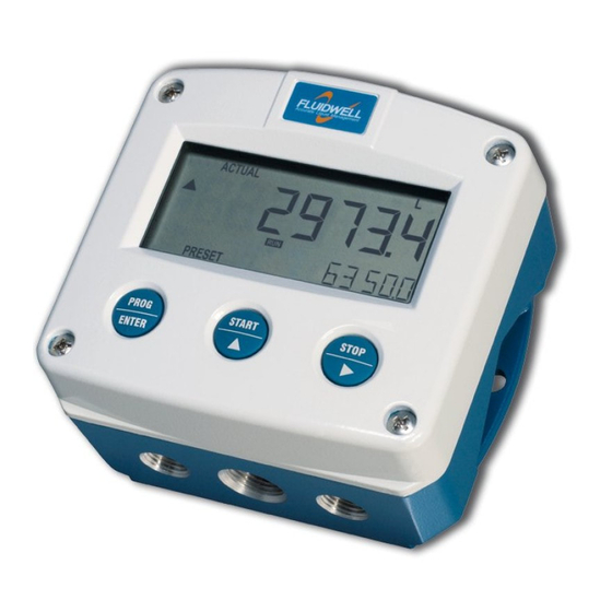
- Page 38 Page 38 LIST OF FIGURES Fig. 1: Typical application for the F090-A-PL. Fig. 2: Control panel. Fig. 3: Example of display information during process. Fig. 4: SETUP matrix structure Fig. 5: Identification – Example of F0-Series identification label (safe area) Fig.
- Page 39 Page 39 FW-F090-A-PL-M_v0404_01_EN.docx...
- Page 40 _ _ _ _ _ _ _ 4.4 pass code 0000 4.5 tagnumber 0000000 Fluidwell bv PO box 6 Voltaweg 23 Website: www.fluidwell.com 5460 AA Veghel 5466 AZ Veghel Find your nearest representative: www.fluidwell.com/representatives The Netherlands The Netherlands Fluidwell bv - © 2022 - FW-F090-A-PL-M_v0404_01_EN.docx FW-F090-A-PL-M_v0404_01_EN.docx...
Need help?
Do you have a question about the F Series and is the answer not in the manual?
Questions and answers