Advertisement
Table of Contents
- 1 Table of Contents
- 2 Precautions and Safety Instructions
- 3 Product Information
- 4 Product Overview
- 5 Installation
- 6 Installation Components
- 7 Adjustment
- 8 Maintenance and Service
- 9 Technical Specifications
- 10 Installation Report
- 11 Product Card
- 12 Warranty
- 13 EC Declaration
- Download this manual
See also:
User Manual
Installation manual
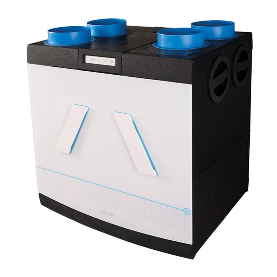
HRC-EcoMax / HRC-MaxComfort
Balanced ventilation system with heat recovery
This manual is intended for installers of the HRC-EcoMax and HRC-MaxComfort
balanced ventilation system. The manual contains important information
about the installation and configuration of the ventilation unit with heat
recovery. The user manual can be found on the right side of the unit.
This manual concerns the following models:
HRC-300 EcoMax
HRC-300-MaxComfort
HRC-300 EcoMax
HRC-400-MaxComfort
HRC-500-EcoMax
HRC-500-MaxComfort
Advertisement
Table of Contents

Related Manuals for Orcon HRC-EcoMax Series


Summary of Contents for Orcon HRC-EcoMax Series
- Page 1 Installation manual HRC-EcoMax / HRC-MaxComfort Balanced ventilation system with heat recovery This manual is intended for installers of the HRC-EcoMax and HRC-MaxComfort balanced ventilation system. The manual contains important information about the installation and configuration of the ventilation unit with heat recovery.
-
Page 3: Table Of Contents
Index 1. Precautions and safety instructions 2. Product information 3. Product overview 4. Installation 5. Installation components 6. Adjustment 7. Maintenance and Service 8. Technical specifications 9. Installation report 10. Product card 11. Warranty 12. EC declaration 1. Precautions and safety instructions •... -
Page 4: Product Information
This results in significant energy savings. The Orcon HRC is equipped with an intelligent electronic control circuit that ensures optimum operation and protection under all circumstances. The unit can be used as a left or right model. - Page 5 • User manual • Connector piece 32mm / G1¼" for condensation drain • 2x Orcon Filter (already in unit) (depending on unit model, see Chapter 2.2) • Optional preheater (depending on unit model, see Chapter 2.2) 2.4 Optional accessories Item...
-
Page 6: Product Overview
index 3. Product overview 3.1 Parts Front cover 9b. Connector flange 180mm (4x) Heat exchanger (HRC-400-EcoMax/MaxComfort) Filter (2x) 9c. Connector flange 180mm (6x) Ventilator module (2x) (HRC-500-EcoMax/MaxComfort) 10. Main circuit board, RF antenna EPP cap (4x) Wall bracket 11. Temperature sensor (2x) Metal back frame 12. - Page 7 index 3.2 Operation Bypass In the summer, or when heat recovery is not desirable, the air is not passed through, but past the heat exchanger thanks to a bypass module. This makes it possible to ventilate the home with fresh outside air in the summer situation, during the night, so that the home is relatively cool again in the morning.
- Page 8 index 3.3 Dimensional drawing...
- Page 9 index 3.4 Duct indicator When connecting the ducts it is important to take into consideration which model is being used - left or right mounting. The connections are indicated on the top of the unit with icons. The unit is supplied as a left model as standard. You can change your apparatus into a right mounted model (see Section 4.3).
-
Page 10: Installation
Mount the Orcon extractor and supply valves in the various rooms Configure the unit in the desired direction (see Chapter 4.3) If desired, replace the earthed power cord with a perilex power cord... - Page 11 index 4.3 Changing the unit direction The HRC is available in a left or right model. The HRC is by default supplied as a left model. The ducts are therefore are connected to the home on the left side of the unit, and the ducts on the right side of the unit go outside.
- Page 12 index 4.4 Electric connectors The HRC is equipped with a earthed power cord as standard. Optionally, you can replace the earthed power cord with a perilex cord (article number: 22915405). The place where the wall socket needs to be fitted is indicated in the figure below.
- Page 13 index Place the white connector of the perilex cord on connection X27. Feed the perilex cord through the cable recess. Place the strain relief in the appropriate recess. 10. Screw the strain relief hand tight using a Torx screwdriver (key size T20) 11.
- Page 14 index Connections to printed circuit board Function Pin function RF antenna connection L – 230V Perilex input 2 – L2 (black, 230V) Medium setting 3 – L1 (grey, 230V) High setting 1- RSA (2x White) Modbus Communication duct to 2- RSB (2x Brown) ventilators 3- GND (2x green) Supply ventilator power supply...
- Page 15 index 4.5 Installing the unit Transformer Add-on PCB Menu button Wall mounting The unit can be hung on the supplied wall bracket. But only if the wall has a minimum mass of 200 kg/m is available. Attach the wall bracket to the wall using the bolts and plugs supplied. Caution: mount the wall bracket using a spirit level before you connect the ducts! Sufficient space must be left underneath the wall bracket for the condensation extractor (see chapter 4.7).
- Page 16 Floor mounting If there is no wall that is suitable for wall mounting, the HRC can also be placed on a concrete floor using the optional Orcon base (article number: 22700080) for floor mounting. Place the legs in the recesses on the bottom of the unit (Figure A). This works best when the unit is on its side.
- Page 17 index Air outlet Air supply Unit fitted with correct filters HRC (install using spirit level) Connect condensation drain according to installation instructions Connect the supply duct using acoustic insulation Connect the extractor duct using acoustic insulation Feed exhaust and supply duct through the roof boarding in such a way that no condensation water is created in the roof boarding and everything is airtight;...
- Page 18 index 4.7 Condensation extractor The HRC must always be fitted with a condensation extractor underneath the unit. It is preferable to use a dry siphon (article number: 22700065), which can be ordered separately. Because this requires less space underneath the unit, there is less chance of air leaks and it does not dry out on hot days, which prevents odour issues.
-
Page 19: Installation Components
index 5. Installation components 5.1 Remote control 15RF (optional) Mounting The remote control can be opened using the push button at the bottom (image below). The wall frame can then be mounted with the 2 screws and plugs supplied or glued. Caution: the "UP" mark on the wall frame must always be at the top. Keep enough space at the bottom so that the push button can be easily reached from below. - Page 20 index • Resetting remote control 15RF To replace a remote control, all components on the unit must be de-registered. All components must then be registered again. A remote control can be reset (and thus de-registered) by simultaneously pressing the ‹absent› and ‹timer› keys for 3 seconds.
- Page 21 index 5.2 CO Roomsensor 15RF Mounting The CO Roomsensor and CO Controlsensor can be opened via the push button on the bottom. The remote control is supplied with 230V mains power. To connect the control to 230V, open the cover for the power supply. This can be opened using a flat head screwdriver.
- Page 22 index Register CO Roomsensor 15RF • On 1 unit Remove the plug from the HRC for 10 seconds. Then return the plug back to the socket. The unit will remain in set-up mode for 3 minutes. Restart the CO sensor by removing it from the wall frame and then replacing it. Press the control button on the CO sensor once briefly, then hold down for 4 seconds until one LED on the right lights up and the status LED flashes red and green alternately.
- Page 23 index There are 2 options: • Energy-saving mode (green) In this mode the unit will ventilate according to the standard requirement. This saves on energy costs; ventilation is only done when it is really needed. • Excellent mode (blue) In this mode, the CO Roomsensor keeps the air quality level at a high level.
- Page 24 After this, the LED on the printed circuit board will remain in set-up for 3 minutes and can be linked with components. If you need support with the installation of the above components, you can always consult our instruction videos at: www.orcon.nl/service/onderhoud/...
-
Page 25: Adjustment
Restart the unit and adjust the unit to setting 2 or 3 Measure the total air volume on the Orcon extractor and supply valves and adjust the air volume for each ventilator if necessary Set the valves to the correct flow rate per room 10. - Page 26 index Adjusting the DIP switches DIP switch number: Setting /h] [m /h] [m /h] 1 · · · · · · · · · · · · · · · · · · · · · · · · Medium 5 ·...
- Page 27 index 6.2 Valves You should preferably use TFF supply valves or EFF extractor valves. When installing the valves, consider the following: • Make sure the supply and extractor valves are at least 1.5 m away from each other so that the airflows cannot come into contact with each other •...
-
Page 28: Maintenance And Service
7. Maintenance and Service 7.1 Maintenance The following components of the Orcon ventilation system must be cleaned regularly: • Filters (cleaned every 3 months and replaced every 6 months, see user manual); • Humidity sensor (at least every 3 years);... - Page 29 index • The humidity sensor can remain in place or easily be removed from the connector. It can then be cleaned carefully using a dry brush. • If the humidity sensor has been removed for cleaning, replace it in the connector after cleaning. White Caution: if the black dot on the sen- sor is facing you, the red wire should...
- Page 30 index Cleaning the heat exchanger The heat exchanger can easily be taken out of the unit with the help of the draw band. The heat exchanger must be cleaned with lukewarm water (max. 40°C). Allow most of the water to drain out and dry the heat exchanger as far as possible before replacing it in the unit.
- Page 31 index Cleaning ventilators The ventilators must be cleaned if they are dirty. The ventilators can be easily reached when the heat exchanger has been removed from the unit. First push down the ventilator module Pay attention to recess in exchange slightly.
- Page 32 index Caution: After replacing the ventilators, they need to be reallocated. The correct allocation is very important for the correct operation of the balance ventilation unit! Disconnect the power supply to both fans on the printed circuit board and unplug the earthed plug from the socket Put the earthed plug back in the socket, wait 10 seconds and pull it out again Connect the supply ventilator power supply to the printed circuit board (connector X13)
- Page 33 Check whether the ventilation unit is connected to the power supply. Register the CO Roomsensor on the ventilation unit according to the instructions. If a malfunction occurs in the CO Roomsensor, then the status LED will 1x flash red repeatedly. Please contact the Orcon service department.
- Page 34 index III. Display The unit has a display on the front (see image below). This display shows the status of the unit by means of a green and a red LED and any error messages are displayed (status LED). An overview of possible indications is shown in the table under 7.2 IV. Printed circuit board IV.
- Page 35 index Set-up mode In the set-up mode, the green LED will burn continuously for 3 minutes. In set-up mode, it is possible to connect multiple RF components to the unit, see chapter 8 for this. In operation After the learning mode, the unit will automatically switch to 'in operation mode'. The unit is working properly.
- Page 36 index Temperature sensor fault When a fault occurs with one of the sensors, the display and the printed circuit board indicate which sensor is malfunctioning. See the connection diagram on page 15 for which sensor is connected to which connector. To verify whether the sensor is defective, you can disconnect it from the connector and measure it (10 kΩ...
- Page 37 index 7.3 Ordering new parts When ordering parts, in addition to the relevant article code number, also specify the unit type, serial number, year of manufacture and the name of the part, for example: Unit type: HRC-300 EcoMax NB.: Unit type and serial Serial Number: 1903570001 number are stated on the...
- Page 38 index Overview article numbers HRC service articles Item Description Item no. Plastic front panel HRC-EcoMax/MaxComfort 22901330 Heat exchanger HRC-EcoMax/MaxComfort 22901303 Filter set HRC-EcoMax (set of 2) Coarse 45% 22700002 Filter set HRC MaxComfort (1x ePM1 70% & 1x Coarse 65% filter) 22700006 Filter set HRC EcoMax (2x Coarse 65% filter) 22700009...
-
Page 39: Technical Specifications
index 8. Technical specifications 8.1 u= HRC-300-EcoMax/MaxComfort Ventilation setting Medium High Maximum Ventilation capacity, factory setting [m Power input [W] depends on setting Permissible resistance duct system 200 Pa at 300 m 760 x 888 x 592 Dimensions [wxhxd] [mm] [height including duct connector pieces] Dimensions duct connection [mm] ø150... - Page 40 index Ventilator graph HRC-300 HRC-300 EcoMax/MaxComfort Flow rate [m Table associated with HRC-300 ventilator graph Work Reference External Power con- Total SPF total point flow rate pressure (Pa) sumption per power con- (Wh/m ventilator (W) sumption (W) 0,11 0,11 0,13 0,14 0,15 0,24...
- Page 41 index 8.2 HRC-400-EcoMax/MaxComfort Ventilation setting Medium High Maximum Ventilation capacity, factory setting [m Power input [W] depends on setting Permissible resistance duct system 200 Pa at 400 m 760 x 888 x 592 Dimensions (W x H x D) [m] (height including channel connection pieces) Dimension of channel connection [mm]...
- Page 42 index Ventilator graph HRC-400 HRC-400 EcoMax / MaxComfort 400 450 Flow rate [m Table corresponding with HRC-400 ventilator graph Work Reference External Power Total power SPF total point Flow rate pressure (Pa) consumption consumption (Wh/m per fan (W) 0,13 0,11 0,13 62,5 0,16...
- Page 43 index 8.3 Unit data HRC-500-EcoMax/MaxComfort Ventilation setting Medium High Maximum Ventilation capacity, factory setting [m Power input [W] depends on setting Permissible resistance duct system 200 Pa at 500 m 760 x 888 x 592 Dimensions (W x H x D) [m] (height including channel connection pieces) Dimension of channel connection [mm]...
- Page 44 index Ventilator graph HRC-500 Flow rate [m Table corresponding with HRC-500 ventilator graph Work Reference External Power Total power SPF total point Flow rate pressure (Pa) consumption consumption (Wh/m per fan (W) 0,13 0,11 0,13 62,5 0,16 0,17 0,20 0,20 0,26 0,23 0,26...
- Page 45 index 8.3 Technical specifications accessories Roomsensor 15RF / CO Controlsensor 15RF Power supply 230 Volts Frequency 50 Hertz Maximum power consumption 1.2 watts Temperature class Dimensions 92 x 92 x 23 mm Weight 125 grams RF frequency 868.3 MHz Min/Max Ambient temperature 0-40°C RV level 0-90% Non-condensing...
-
Page 46: Installation Report
index 9. Installation report Date Address Place Project type Property type Client Installed by Measured by Unit type Serial number Set flow rate: Dip switch no .: 1 Extractor [X34] on/off on/off on/off on/off on/off on/off on/off on/off Supply [X35] on/off on/off on/off... - Page 47 index Overview of maintenance services Date Activity Initials Registered RF components Other remarks...
-
Page 48: Product Card
10. Product fiche Supplier Orcon Model HRC-300-EcoMax HRC-300-MaxComfort Specific energy consumption Climate Cold Average Warm SEC class Typology Bidirectional Type drive Multi-speed Type heat recovery Recuperative η Thermal efficiency Maximum flow rate Electric power input Sound power level Reference flow rate... - Page 49 index HRC-400-EcoMax HRC-500-EcoMax HRC-400-MaxComfort HRC-500-MaxComfort kWh/[m ·A] Cold Average Warm Cold Average Warm dB[A] 0,078 0,097 0,17 0,19 W/[m CTRL MISC CTRL MISC 0,85 0,85 Internal Internal External External 1,76 1,76 1,76 kWh/[m ·A] 91,0 46,5 21,0 90,30 46,16 20,87 kWh/[m ·A] Cold...
-
Page 50: Warranty
(Dis) assembly costs on site are not covered by the warranty. If a defect occurs within the warranty period, this must be reported to the installer. Orcon bv reserves the right to change the construction and/or configuration of its products at any time without the obligation to adjust previously delivered products. - Page 51 index Voldoet aan de bepalingen gesteld in de richtlijnen | Répond aux exigences des direc- tives | Entspricht den Anforderungen in den Richtlinien | Complies with the require- ments stated in the directives: • Machinery Directive 2006/42/EC • Low Voltage Directive 2014/35/EU. •...
- Page 52 Landjuweel 25, 3905 PE Veenendaal | Postbus 416, 3900 AK Veenendaal t +31 (0)318 54 47 00 | info@orcon.nl | www.orcon.nl...
Need help?
Do you have a question about the HRC-EcoMax Series and is the answer not in the manual?
Questions and answers