Advertisement
Table of Contents
Installation manual
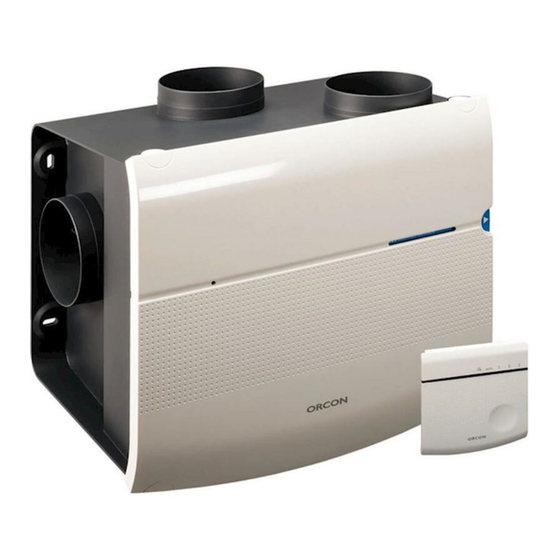
MVS-15RH Domestic ventilation
This manual is intended for users and installers of the MVS-15RH mechanical ventilation system. This manual contains
important information about the installation and configuration of the domestic ventilator.
The user manual can be found at the back of this manual.
This manual concerns the following models:
MVS-15RH, MVS-15RHB, MVS-15RHP, MVS-15RHB CO
2
Advertisement
Table of Contents

Related Manuals for Orcon MVS-15RH


Summary of Contents for Orcon MVS-15RH
- Page 1 Installation manual MVS-15RH Domestic ventilation This manual is intended for users and installers of the MVS-15RH mechanical ventilation system. This manual contains important information about the installation and configuration of the domestic ventilator. The user manual can be found at the back of this manual.
-
Page 2: Table Of Contents
1. Only a professional installer may install, connect, commission and maintain the device unless otherwise 1. Safety page 2 specified in this document; 2. Installing the MVS-15RH domestic ventilator. page 3 2. The installation of the device must be performed in 3. Electrical installation page 6 accordance with the general and locally applicable 4. -
Page 3: Installing The Mvs-15Rh Domestic Ventilator
The motor and the receiver PCB are mounted on the motor plate. The humidity sensor is on the receiver PCB . 10. . Set the DIP switches of the MVS-15RH device on the receiver PCB, and adjust the valves. See the chapter... - Page 4 Installation so that the push button can be easily reached from below. The installation must be implemented with as little It is recommended that the remote control is installed in an resistance as possible in the ducts. Long flexible tubes easily accessible place in the living room, kitchen or lavatory.
- Page 5 Fig. 4. Rear view with Ø 160 mm connection Fig. 2 Side view MVS-15 Fig. 3 Top view MVS-15 Fig. 5 Base view with Ø 125 mm and Ø 160 mm connection...
-
Page 6: Electrical Installation
List of DIP switch functions Battery position Options DIP switch Wall frame Table A curve speeds Table B curve speeds 15-minute afterrun humidity sensor Upper part Push button to open control 30-minute afterrun humidity sensor Fig. 6 Exploded view RF remote control Red/green LED 3. -
Page 7: Adjustment Of Air Volume
Electrical connection domestic ventilator 3. Set the device to position 2 or 3 (depending on the size The MVS-15RH is equipped with a cord and earthed plug for of the home). connection to the power supply. The device can be switched 5. - Page 8 Table a curve Power Position DIP switch position Air output Pressure speed consumption Setting [Pa] (Number) Absent *Low Off 70 Off 85 *Medium Off 150 Medium Off 171 Medium Off 197 Medium Off 222 Medium Off 245 Medium Off 270 Medium Off 293 Medium...
- Page 9 Table b curve Power Position DIP switch position Air output Pressure speed consumption Setting [Pa] (Number) Absent Medium Medium Medium Medium High High High High High High High High Table B - Table A or B is selected by setting DIP switch 7 to on or off.
-
Page 10: Configuration En Pairing
5. Configuration and pairing Table 3 DIP switch function 7 and 8 The MVS-15RH is equipped with a receiver PCB on the Options DIP switch motor plate. A separate remote control and/or CO room sensor must be paired with the receiver PCB. - Page 11 In automatic mode, the MVS-15RH will switch to position Reset remote control 2 when humidity levels increase. The time that the domes- A remote control can be reset by pressing the ‹absent› and tic ventilator continues to operate in this mode depends ‹timer›...
-
Page 12: Service And Maintenance
CO room sensor is carried out in the same way as pairing CO room sensor number 1. The following parts of the Orcon ventilation system must be cleaned regularly: Unpairing remote control(s) and CO room sensor(s) • Housing - at least every 2 years;... - Page 13 Removing and installing front cover Removing and installing motor plate Remove the plug from the wall socket. Open the front cover After the front cover has been removed, the motor plate can of the device with a flathead screwdriver (fig. 9), after which be lifted out with the two handles (arrows fig.
- Page 14 Indication LED on the device The green LED on the receiver PCB indicates the scenario status of the MVS-15RH. When the LED repeatedly flashes green once, the MVS-15 is operating normally. If the LED repeatedly flashes green twice, the MVS-15RH is in position 2 or 3 due to increased humidity levels.
-
Page 15: Technical Data
7. Technical data Table 5 List of scenarios shown on device Function (notification) Device indication green: Normal operation, no hu- Flashing green 1x MVS-15RH midity, CO or timer signal. Supply voltage: 200-240 V single phase 50 Hz Humidity scenario active... - Page 16 RF CO sensor RF remote control Supply voltage: Supply voltage: 230 V Powered by 3 V battery Frequency Temperature class 50 Hz Max. power consumption Dimensions 83 x 80 x 28 mm Temperature class Temperature class Dimensions Dimensions 92 x 92 x 23 mm 83 x 80 x 28 mm Weight Weight...
-
Page 17: Guarantee
8. Guarantee 9. EC declaration of conformity Orcon BV guarantees the fan for two years as standard. Orcon BV Landjuweel 25 The guarantee period starts on the production date. The guarantee is void if: 3905 PE Veenendaal, NL Tel.: +31 (0)318 54 47 00 •... -
Page 18: Installer's Installation Report
10. Installer’s installation report Installation report DIP switch Setting Date: on/off Address: on/off Town or City: on/off Type of project: on/off Type of property: on/off Client: on/off Installed by: on/off Measured by: on/off Type of device: * Circle applicable setting Serial number:... - Page 19 Space / valve Position on device Required [m Measured m Setting MKL valve (1-6) Kitchen Lavatory Bathroom...
- Page 20 You and your home need fresh Orcon exceptional indoor climate? air! Opening a window for a bit is not enough. The moment Our objective is to offer occupants an exceptional indoor you close the window, the fresh air disappears.
- Page 21 These different setting options measurement report. ensure that cooking odours and humidity are efficiently removed from the home. The MVS-15RH system was designed to operate 24 hours per day. The device is 2. How does the ventilation system work? equipped with a highly energy-efficient EC motor to keep energy consumption to a minimum.
- Page 22 B. (Self-regulating) grilles in the windows, window frames or sliding patio door, for the supply of fresh outside air. C. Ductwork for the extraction of stale air to the MVS-15RH. D. Remote control for operating the MVS-15RH device. E. CO room sensor(s), (MVS-15RHB CO F.
- Page 23 Remote control operation Besides the 4 positions, this control also has intelligent Your device is controlled by 6 buttons. The table below humidity and CO detection (with optional CO room sen- explains the functions of these buttons. sor). This is activated when automatic mode is selected. Automatic mode (auto) In auto mode, the device operates in accordance with 15RF Remote control user interface explanation...
- Page 24 Control button Wall frame MVS-15RH to extract more or less stale air from the kitchen, bathroom and lavatory. As a result, a greater or Fig. 2 Location LED and control button on CO...
- Page 25 Rinse the valve well afterwards, and wipe dry. Replace the MVS-15RH ventilation cabinet. When the remote control valve in the wall or ceiling. is set to automatic mode, the MVS-15RH reacts to the highest level of CO (air quality in a living area) as measu-...
- Page 26 It is a task you can easily do yourself. The battery can be ordered from www.orcon.nl. To replace the battery, click in the push button on the wall frame (figure 3) of the remote...
- Page 27 5. Guarantee Disassembly and removal At the end of the service life of the MVS-15RH, Orcon BV guarantees the fan for two years as standard. the user is responsible for the safe disassembly The guarantee period starts on the production date.
Need help?
Do you have a question about the MVS-15RH and is the answer not in the manual?
Questions and answers
datasheets for the MVS-15RH mechanical ventilation system: Noise Level: The unit operates at a noise level of approximately 30 dB(A)
The datasheets for the Orcon MVS-15RH mechanical ventilation system include the following specifications:
- Power Supply: 230 V, 50 Hz
- Max. Power Consumption: 4 W
- Motor Type: Efficient EC motor
- Temperature Class: T40
- Ambient Temperature Range: 0-40 °C
- Humidity Range: 0-90% RH (non-condensing)
- Weight: 4.4 kg
- Dimensions:
- Height: 389 mm (467 mm with connections)
- Width: 449 mm
- Depth: 303 mm
- Protection Class: IP30
- Control Options: Remote control and/or CO2 room sensor
- Communication Frequency: 868.3 MHz (RF)
- Error Indications:
- Flashing red 1x: Motor not running
- Flashing red 2x: No value from humidity sensor
- Flashing red 3x: RF communication failure
- Functional Range of CO2 Sensor: 400 - 2000 ppm
These details provide a technical overview of the Orcon MVS-15RH system.
This answer is automatically generated