Advertisement
Quick Links
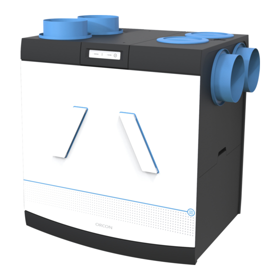
Installer's manual
HRC-EcoSmart / HRC-SmartComfort
Balanced ventilation with heat recovery &
solar control
This manual is intended for installers of the HRC-EcoSmart and HRC-
SmartComfort balanced ventilation system. The manual contains important
information about the installation and configuration of the ventilation unit.
These instructions belong to the versions:
HRC-425-EcoSmart
HRC-425- SmartComfort
HRC-570-EcoSmart
HRC-570-SmartComfort
Advertisement

Related Manuals for Orcon HRC-570 EcoSmart


Summary of Contents for Orcon HRC-570 EcoSmart
- Page 1 Installer's manual HRC-EcoSmart / HRC-SmartComfort Balanced ventilation with heat recovery & solar control This manual is intended for installers of the HRC-EcoSmart and HRC- SmartComfort balanced ventilation system. The manual contains important information about the installation and configuration of the ventilation unit. These instructions belong to the versions: HRC-425-EcoSmart HRC-425- SmartComfort...
-
Page 3: Table Of Contents
Table of contents Precautions and safety instructions Product information Product overview Installation Sign in componenten Adjustment Maintenance and Service Technical specifications Installatierapport 10. Product card HRC 11. Warranty 12. EG-statement... -
Page 4: Precautions And Safety Instructions
index 1. Precautions and safety instructions Indicates a risk of personal injury and/or material damage to the product, the system or the environment. Risk of electric shock. • Only a professional installer may install, connect, commission and service the unit unless otherwise specified in this document; •... - Page 5 index 2. Product Information 2.1.General Product Description The HRC-EcoSmart / SmartComfort is a balance fan with heat recovery and zone control. This means that the same amount of fresh, filtered outside air is supplied to the living rooms and bedrooms as is removed from the kitchen, bathroom and toilet.
- Page 6 index...
- Page 7 • User Manual • Coupling 32mm / G1¼" for condensate drain • 2x Orcon Filter (already in unit) (depending on unit version, see chapter 2.2) • Optional pre-heater (depending on unit version, see chapter 2.2) • 2x Zone valve •...
- Page 8 index 2.4.Optional accessories Articl Article HRC chassis 22700080 EFF ø125 Exhaust valve 23121002 EFF ø160 Exhaust valve 23121003 TFF ø125 Supply valve 23121012 TFF ø160 Supply valve 23121013 MKL-T ø125 Supply valve plastic 23120125 MKL-T ø160 Supply valve plastic 23120160 Dry condensation drain set 22700065 Filter set HRC 2x coarse 65%...
-
Page 9: Product Overview
index 3. Product overview 3.1.Parts Plastic front cover 10. Main board, RF antenna Heat exchanger 11. Temperature sensor (2x) Filter (2x) 12. Humidity sensor Fan module (2x) 13. Bypass module EPP cap (4x) 14. Metal front plate Wall bracket 15. Filter handle left & right Metal backing plate 16. - Page 10 index 3.2.Appliance operation Zone control The HRC-EcoSmart and HRC-SmartComfort are equipped with two zone valves. With these, the supply air can be divided over two different zones. The sensors, which are placed in the two zones, determine where ventilation is required. By applying zone control, ventilation is minimised in rooms where it is not necessary and maximised where it is.
- Page 11 index 3.3.Dimension drawing 127160 220160 Condensate drain G1 1/4'' S1 = 600 For service purposes, allow +/- 600 mm of free space at the front of the unit. Position the double wall socket within 1 metre of the appliance.
-
Page 12: Installation
index 4. Installation 4.1.Requirements for installation The installation of the HRC must be carried out in accordance with: • Quality requirements for domestic ventilation systems, ISSO 61 • Quality requirements for balanced ventilation in dwellings, ISSO 62 • The capacity calculation according to the Building Act •... - Page 13 4.6 (200kg/m2), or mount the unit on the optional stand in case of floor mounting. Step 2 Install the Orcon exhaust and supply valves in the see 4.8 various rooms. Step 3 Install the ventilation ducts and lead-throughs with as little see 4.3...
- Page 14 Step 9 Install the condensate drain (preferably dry siphon) see 4.9 under the appliance index Step 10 Place the desired controls in the house. see 4.10 At least one sensor must be installed per zone. Step 11 Connect the zone valves het toestel. see 5.1 Step 12 Connect the sensors to the zone valves of the...
- Page 15 index Step 14 Adjust the supply valves for each zone in accordance with see 6.3 the ventilation calculation made. Step 15 Adjust the drain valves over the entire house by see 6.4 opening both zone valves 4.3.Installing channels 1. Exhaust to the outside. 2.
- Page 16 index...
- Page 17 index Selecting air ducts m3/h Minimum recommended duct diameter (mm) Desired flow rate ( 0 - 30 > 100 30 - 150 > 125 150 - 350 > 150 350 - 450 > 180 400 - 500 2x 180 (use side and top connection) Please observe the following points when installing the channels: 1.
- Page 18 Left-hand Right-hand index Wall Propert Outside Propert Caution: When inserting the ducts, make sure that no residual material enters the unit, as this may damage it. 4.4.Change device orientation When connecting the ducts, it is important to take into account where the ducts should be placed.
- Page 19 index Change the appliance to the right-hand version: Step 1 Remove the plug from the socket. Step 2 Place the unit on a flat surface, if the unit is already hung. Step 3 Remove both filter handles. Step 4 Remove the plastic front plate. Step 5 Remove the metal front plate of the unit by loosening the 5 screws.
- Page 20 index 4.5. Electrical connections HRC The HRC is equipped as standard with a mains lead with shock-proof plug. Optionally, you can replace the rim-earth cord by a perilex cord (article number: 22915405). The zone control is provided with its own 5 volt power supply and must be connected to a wall socket by means of the supplied adapter.
- Page 21 index Execute HRC with perilex cable The HRC can also be operated with a 3 position switch (CV-3 switch). For this, the HRC must be fitted with a perilex mains lead, which is optionally available. Follow the next steps. Note: Make sure the wall socket is de-energised when changing the wiring.
- Page 22 index Step 9 Lead the perilex cable through the cable recess. Place the strain relief in the appropriate recess. Step 10 Replace the top cover and tighten the 2 screws. If the cable from the display has come loose, reinsert it in the connector on the top panel. Step 11 Replace the Perilex cable in the cable clamp on the metal back frame Step 12 Plug the plug into a Perilex socket.
- Page 23 index 4.6.Placing the appliance Wall mounting The unit can be hung on the wall bracket provided. The wall must have a minimum mass of 200kg/m2 for optimum soundproofing. Step 1 Fix the wall bracket level to the wall using the bolts (M8x60 wood screw) and plugs supplied.
- Page 24 Floor mounting If there is no wall suitable for wall mounting, the HRC can also be placed on a concrete floor using the optional Orcon undercarriage (article number: 22700080) for floor mounting. Step 1 Insert the feet into the recesses on the underside of the unit (Figure A).
- Page 25 index 4.7.Connecting zone valves The zone valves must always be placed in two separate supply channels that are connected to two different zones. On the device, the connections for the supply ducts are marked with the following icon: The zone valves can be placed either directly on the unit or externally in the supply duct.
- Page 26 index Connect zone valves directly to the unit. Step 1 Place the two connecting flanges for the zone valves (with recess) on the inlet connections of the unit marked with the icon: Make sure that the flanges are tightened to the mounting points of the unit, so that the valves are properly positioned.
- Page 27 index...
- Page 28 index Install zone valves in the supply duct. Step 1 Place the standard connection flanges for duct mounting on the inlet connection of the unit marked with the icon: Make sure that the flanges are tightened to the mounting points of the unit, so that the valves are properly positioned.
- Page 29 4.8.Installing valves Preferably use Orcon supply and extract valves. The following points must be taken into account when installing the supply and return valves: • Select the location of the supply valves in such a way that contamination and draughts are avoided.
- Page 30 Prevent this from drying out in periods when there is little condensation. An Orcon dry trap (article number: 22700065) is preferred, which can be ordered separately. This requires less space under the device, there is no risk of air leaks...
- Page 31 index 4.10.Installation accessories In order to determine the zone in which ventilation is required, one or more sensors must be used per zone. The sensor determines the air quality in the room by measuring the content. Depending on the measured content, the zone valves are partially opened or closed.
- Page 32 index 5. Subscribe components When the HRC including the zone valves has been installed, the various components can be registered. These are registered in accordance with the following steps. Registering zone valves on HRC Connecting sensors to zone valves 5.1.Registering zone valves on HRC The zone valves must be registered on the device.
- Page 33 index 5.2.Connecting sensors to a zone valve After the zone control has been registered on the HRC, at least one sensor per zone must be registered on the zone valve connected to the relevant zone. Please follow the steps below: Step 1Open the cover on the housing of Zone valve 1 so that the circuit board is visible.
- Page 34 index Register additional sensors It is possible to connect multiple sensors per zone. For example, when several bedrooms in a zone are equipped with a sensor. For this purpose, the above steps are repeated with each new sensor. If several sensors are placed in one zone, the sensor with the highest value determines the ventilation requirement for the zone concerned.
-
Page 35: Adjustment
index 6. Adjustment 6.1.Set flow rate to HRC The air volume per fan can be set using the DIP switches on the HRC circuit board. The upper row of DIP switches (X34) controls the extract air fan and the lower row (X35) controls the supply air fan. - Page 36 index Please note that the return air is not zoned and the 70% rule does not apply here. If the required exhaust air capacity is higher than 70% of the supply air capacity, this capacity must be entered on the unit. Setting device capacity Step 1 Close the windows and doors.
- Page 37 index Setting DIP switches HRC-30 HRC-40 Positio DIP switch number: m3/h m3/h Middle Middle Middle Middle High High High High High High High High...
- Page 38 High index High High High High High High High * Factory setting...
- Page 39 To set the air distribution, follow the steps below: Step 1 Calculate the percentage distribution of both zones in relation to the total housing capacity. See the example below. See www.orcon.nl to use our calculation tool. Voorbeeld:...
- Page 40 index Short Zone 1 Zone 1 press percentage percentage Zone 1 Zone 2 button Orange Orange Orange Green Orange Orange Green Green Orange Orange Green Orange...
- Page 41 index 6.3.Airside regulation of zones By means of the adjustment mode, the supply and exhaust air per zone can be adjusted and controlled. Both zones are controlled in position 3. Follow the steps below: Step 1 Press the button of <Zone 1> for 8 seconds, until LED 1 flashes orange. Step 2 After releasing the button, the zone 1 adjustment mode is activated.
- Page 42 index 6.4.Adjusting drain valves The exhaust valves are not zoned. After the supply valves in both zones have been calibrated, the extract valves must be calibrated over the entire house. Set the HRC to position 3 so that both zone valves on the supply air open. Measure the total air quantity on the exhaust valves and check whether you are exhausting enough air per room according to the ventilation calculation made.
-
Page 43: Maintenance And Service
index 7. Maintenance and Service 7.1.Maintenance To keep the unit in good condition, it should be inspected and cleaned regularly. Maintenance of the device may only be carried out by qualified persons. The following components must be checked and maintained according to the following schedule: Section Interva... - Page 44 index Cleaning the humidity sensor The humidity sensor is located in the drainage duct from the house. This channel is marked with: Step 1 Open the top or side connection of the exhaust duct. If both connections have a channel, the sensor can be reached from inside by removing the heat exchanger.
- Page 45 index Cleaning the heat exchanger Step 1 Remove the front metal cover and both filters. Step 2 Remove the heat exchanger by sliding it out of the unit using the pull strap. Make sure that there is at least 60 cm space at the front of the device.
- Page 46 index Cleaning fans Danger of electrocution! Maintenance work on the fans must be carried out with the HRC switched off. Danger! Make sure that the fans do not rotate when they are removed. The device must be de-energised for at least 20 seconds before the fans are removed.
- Page 47 index Step 8 Tilt the fan. Step 9 Remove both connectors. Step 10 Clean the fan with compressed air or a brush, do not use water. Step 11 Check whether the anemometer at the outlet of the fan can still rotate freely.
- Page 48 index 7.2.Service The unit is fitted with a display on the front. The display shows the current status of the unit; for the indications, see the overview on the next page. When the unit is operating correctly, the status LED will blink green repeatedly. If there is a fault in the unit, it will are shown on the display.
- Page 49 index HRC status Indication Report Learning mode active solid green Starting up the device Temporary orange Normal operation 1x short green Moisture scenario active 2x short green Control on active 3x short green Timer active 4x short green Bypass active 5x short green Change filter 1x green 1x red + Filter LED...
- Page 50 index Status LED Zone 1 Status LED Zone 2 Menu buJons: Zone 1 Zone 2 Zone valve 1 is equipped with a printed circuit board with 2 LEDs that display the status of the zone control. In the overview below, the different displays are shown. Zone valve status Indication Message Status LED...
- Page 51 index 7.3. Device status description Learning mode Indication: Description: Starting up the Continuous In teach-in mode, the green LED will light continuously for green three minutes. During the teach-in mode, it is possible to connect multiple RF components to the device. Indication: Description: Temporary...
- Page 52 index Timer Indication: Description: Flashin If a temporary mode has been activated by means of a g green connected control, the unit will run in the high mode during this active period. Temperature Change filter Indication: Description: Filter LED When the filter lamp lights up, the filter should be green checked.
- Page 53 2x red When this message is displayed, the unit has made an index emergency stop. This means that the measured input air orange temperature is lower than 5°C. In this case, check how the unit is oriented (left or right) and whether the ducts are connected correctly.
- Page 54 index Temperature sensor Indication: Description: 2x red If a "temperature sensor defective" message is active, no 2-5x orange sensor value can be read out. Check which sensor is defective. Humidity sensor Indication: Description: 3x red If the message "moisture sensor defective" is active, no sensor value can be read out.
- Page 55 index 7.5.Assigning fans Attention: After replacement of the fans, they must be assigned again. Correct assignment is very important for the correct operation of the balanced ventilation unit! Step 1 Disconnect the device from the power supply. Step 2 Disconnect the power supply of both fans (connection X 13 and 14) from the board.
- Page 56 index 7.6.Service parts Type of device:HRC-425-EcoSmart Serial number:2003570001 (See type label) Year built: 2020 (see type sticker) Part: Filter set HRC EcoMax Artikelnummer:22000080 N.B.: Type of appliance and serial number are indicated on the type plate on the front of the appliance.
- Page 57 index Overview of service article numbers HRC Article description Article no. Plastic front cover HRC 22901330 Heat exchanger HRC 22901303 Filter set (set of 2) Coarse 45% HRC-EcoSmart 22700002 Filter set (1x ePM1 70% & 1x Coarse 65% filter) HRC- 22700006 SmartComfort Filter set (2x Coarse 65% filter) HRC-EcoSmart...
- Page 58 Perilex cable HRC 22915405 index Side-earthed cable HRC 22915426...
-
Page 59: Technical Specifications
index 8. Technical specifications 8.1.Connections circuit board HRC No. Function RF antenna connection U.FL connector 1 - 230V output Perilex input 2 - L2 (black, 230V) position Middle 3 - L1 (grey, 230V) position High 1.- RSA (2x White) 2.- RSB (2x Brown) Modbus Communication Fans* 3.- GND (2x Blue) 230V supply fan... - Page 60 index Transformer U.FL-R-SMT-1 Antenna connector Only suitable for controlling ventilators...
- Page 61 index 8.2.Connections circuit board Zone control Functi Connector Zone 1 Connector Zone 2 Micro USB socket for power supply Button 1 Menu button zone 1 Button 2 Menu button zone 2 BuJon BuJon...
- Page 62 index 8.3.Device data for HRC-425-EcoSmart / SmartComfort (300) Device data for HRC-425-EcoSmart/SmartComfort Ventilation mode Middl Maximu Ventilation capacity, factory setting [ m3/h Reference pressure [Pa] Power consumption [W] depending on setting Permissible resistance channel system 200 Pa at 300 m3/h Dimensions (wxhxd) [mm] 760 x 931 x 592 (height including zone valves)
- Page 63 index Ventilator diagram HRC-425 (300) Flow rate [ m3/h Workpoi Refere External Power Total power SFP total (Wh/m3) pressure consumpti consumptio (Pa) flow on per fan n (W) rate ( 0,11 0,11 0,13 0,14 0,15 0,24 0,22 0,26 0,31...
- Page 64 index 8.4.Device data HRC-570-EcoSmart/SmartComfort (400) Ventilation Laag Medium High Maximum Ventilation capacity, factory setting [ m3/h Reference pressure [Pa] Power consumption [W] depending on setting Permissible resistance channel system 200 Pa at 400 m3/h Dimensions (wxhxd) [mm] 760 x 931 x 592 (height including zone valves) Duct connection diameter [mm] ø160 (Zone valves supply)
- Page 65 index Ventilator diagram HRC-570 (400) m3/h Flow rate [ Workpoi Refere External Power Total power SFP total pressure (Wh/m3) consumpti consumptio (Pa) flow on per fan n (W) rate ( 0,13 0,11 0,13 62,5 0,16 0,16 0,18 0,20 0,26 0,26 0,32 0,27...
- Page 66 0,32 index 0,40...
- Page 67 index 9. Installation report Date Address Location Type of project House type Client Installed by Measured by Type of device Serial number Set flow rate: Dipswitch no.: Drainage on/off on/off on/off on/off on/off on/off on/off on/off [X34] Supply [X35] on/off on/off on/off on/off...
- Page 68 Other index Settings Zone control m3/h m3/h Inlet Zone 1/2 Ratio setting Required [ Measured [ Zone 1 Zone 2 Drainage n.a. house...
- Page 69 index Overview of maintenance operations Date Activity Initials Registered RF components Other remarks...
-
Page 70: Product Card Hrc
Product card HRC Manufacturer | Supplier Orcon Type | Model | Modellkennung HRC-4 HRC-5 EcoSm EcoSm HRC-4 HRC-5 Smart Smart Comfo Comfo Specific energy consumption | Cold Avera Warm Cold Avera Warm Specific energy consumption Froid C h a u... - Page 71 | Auf | Auf display display Installation instructions | Instructions de montage | www.orcon.nl www.orcon.nl Anweisungen für Anbringung Internet address | Internet adresse www.orcon.nl www.orcon.nl Drukschommeling | Airflow sensitivity | Variations de pression - – - –...
-
Page 72: Warranty
(De)assembly costs on site are not covered by the guarantee. If a defect occurs within the guarantee period, this must be reported to the installer. Orcon bv reserves the right to change the construction and/or configuration of its products at any time without the obligation to replace products previously delivered. - Page 73 index index Conforms to the requirements stated in the directives | Répond aux exigences des directives | Entspricht den Anforderungen in den Richtlinien | Complies with the requirements stated in the directives: • Directive 2014/53/EU (RED) • Directive establishing a framework for the setting of ecodesign requirements for energy-related products 2009/125/EC •...
- Page 74 Landjuweel 25, 3905 PE Veenendaal | PO Box 416, 3900 AK Veenendaal t +31 (0)318 54 47 00 | info@orcon.nl | www.orcon.nl...
Need help?
Do you have a question about the HRC-570 EcoSmart and is the answer not in the manual?
Questions and answers