Emerson Rosemount Reference Manual
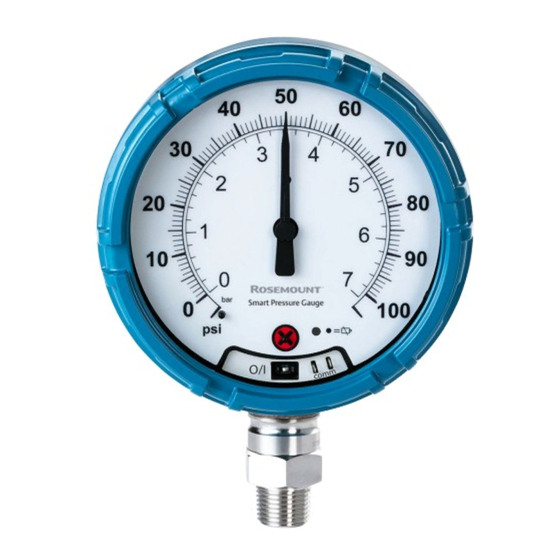
Smart pressure gauge
Hide thumbs
Also See for Rosemount:
- Reference manual (252 pages) ,
- Quick start manual (52 pages) ,
- Quick install manual (25 pages)
Table of Contents
Advertisement
Quick Links
Download this manual
See also:
Reference Manual
Advertisement
Table of Contents

Related Manuals for Emerson Rosemount


Summary of Contents for Emerson Rosemount
- Page 1 Reference Manual 00809-0100-4145, Rev AB September 2019 ™ Rosemount Smart Pressure Gauge...
- Page 2 Changes or modifications to the equipment not expressly approved by Rosemount Inc. could void the user’s authority to operate the equipment. Using the Rosemount Smart Pressure Gauge in a manner other than what is specified by the manufacturer may impair the protection provided by the equipment.
- Page 3 WARNING Physical access Unauthorized personnel may potentially cause significant damage to and/or misconfiguration of end users’ equipment. This could be intentional or unintentional and needs to be protected against. Physical security is an important part of any security program and fundamental to protecting your system. Restrict physical access by unauthorized personnel to protect end users’...
-
Page 5: Table Of Contents
2.1 Overview............................9 2.2 Safety messages..........................9 2.3 Considerations..........................9 2.4 Installation procedure........................12 2.5 Impulse piping considerations......................14 2.6 Process connection........................15 2.7 Rosemount manifolds........................16 Chapter 3 Configuration.......................21 3.1 Overview............................21 3.2 Safety messages..........................21 3.3 System readiness..........................21 3.4 Configuration basics........................22... - Page 6 Contents Reference Manual September 2019 00809-0100-4145 Emerson.com/Rosemount...
-
Page 7: Chapter 1 Introduction
Field Communicator menu trees provides full menu trees and abbreviated fast key sequences for commissioning tasks. Models covered This manual covers the Rosemount Smart Pressure Gauge. • Measures gage/absolute/compound/vacuum pressure up to 10,000 psi (689.5 bar) Product recycling/disposal Recycling of equipment and packaging should be taken into consideration and disposed of in accordance with local and national legislation/regulations. - Page 8 Introduction Reference Manual September 2019 00809-0100-4145 Emerson.com/Rosemount...
-
Page 9: Chapter 2 Hardware Installation
The information in this section covers installation considerations. A Quick Start Guide is shipped with every device to describe basic installation and startup procedures. ™ Dimensional drawings for the Rosemount Smart Pressure Gauge can be found in the Product Data Sheet. - Page 10 The device needs to be turned on in order for the Field Communicator to interface with the Rosemount Smart Pressure Gauge. The Field Communicator connection is located to the right of the ON/OFF switch. To communicate with the device, connect the Field Communicator to connections labeled “COMM”.
- Page 11 2.3.4 Electrical Battery The Rosemount Smart Pressure Gauge is self-powered. The battery contains approximately five grams of lithium. Under normal conditions, the battery materials are self-contained and are not reactive as the battery is maintained inside the enclosure of the device.
-
Page 12: Installation Procedure
Use wrench on flats, not on housing. Mounting orientation The low side pressure port (atmospheric reference) on the pressure gauge is located in the neck of the device behind the housing. The vent path is between the housing and sensor. Figure 2-3. Emerson.com/Rosemount... - Page 13 During the power sequence, the dial tests full range of motion and LED flashes amber. 3. Once the power sequence ends, verify the LED flashes green. Note The LED may display several colors; see Table 4-2 for device statuses. Emerson.com/Rosemount...
-
Page 14: Impulse Piping Considerations
Mount drain/vent valve upward to allow gases to vent. Gas flow measurement • Place taps in the top or side of the line. • Mount the device beside or above the taps so to drain liquid into the process line. Emerson.com/Rosemount... -
Page 15: Process Connection
A low side pressure port (atmospheric reference). WARNING Do not apply torque directly to the sensor module. Rotation between the sensor module and the process connection can damage the electronics. To avoid damage, apply torque only to the hex-shaped process connection. Emerson.com/Rosemount... -
Page 16: Rosemount Manifolds
Hardware installation Reference Manual September 2019 00809-0100-4145 Rosemount manifolds The Rosemount 306 Integral Manifold mounts directly to the device. The manifold is used with this device to provide block-and-bleed valve capabilities of up to 10,000 psi (689.5 bar). 2.7.1 Installation procedure The Rosemount 306 Integral Manifold is for use only with a Rosemount Smart Pressure Gauge. - Page 17 2. To bring the device to atmospheric pressure, open the vent valve or bleed screw. Note A ¼-in. male NPT pipe plug may be installed in the test/vent port and will need to be removed with a wrench in order to vent the manifold properly. Emerson.com/Rosemount...
- Page 18 3. After venting to atmosphere, perform any required calibration and then close the test/vent valve or replace the bleed screw. Device Test/vent (closed) Isolate Process (closed) 4. Open the Isolate (block) valve to return the device to service. Device Test/vent (closed) Isolate Process (open) Emerson.com/Rosemount...
- Page 19 September 2019 Adjusting valve packing Over time, the packing material inside a Rosemount manifold may require adjustment in order to continue to provide proper pressure retention. Not all Rosemount manifolds have this adjustment capability. The Rosemount manifold model number will indicate what type of stem seal or packing material has been used.
- Page 20 Hardware installation Reference Manual September 2019 00809-0100-4145 Bonnet Stem Packing Ball seat Packing adjuster Jam nut Packing follower Emerson.com/Rosemount...
-
Page 21: Chapter 3 Configuration
Confirm correct device driver ™ Verify the latest Device Description (DD/DTM ) is loaded on your systems to ensure proper communications. Procedure 1. Visit the Emerson Device Install Kits Library or Fieldcommgroup.org. 2. Select desired product. a) Within Table 3-1, use the HART Universal Revision and Device Revision numbers to find the correct Device Description. -
Page 22: Configuration Basics
Configuration Reference Manual September 2019 00809-0100-4145 Table 3-1: Rosemount Smart Pressure Gauge Device Revisions and Files Software Identify device Find device driver Review Review release instructions functionality date NAMUR NAMUR HART HART Device Manual Changes to software software software universal... -
Page 23: Basic Gauge Setup
4. Follow the commands to perform the procedure. 3.5.2 Activate wireless Do not activate wireless until Emerson Wireless Gateway is installed and functioning properly; toggling off and on reduces battery life. Join device to network. 1. Obtain Network ID and Join Key for the wireless network (available in wireless gateway). -
Page 24: Configuration Verification
Reference Manual September 2019 00809-0100-4145 Note Devices are shipped from Emerson fully calibrated to the factory default of full scale (scale range = upper range limit). From the HOME screen, enter the Fast Key sequence. Fast Keys 2, 2, 1, 2 Procedure 1. - Page 25 From the HOME screen, enter the Fast Key sequence. Fast Keys 3, 2, 1 Procedure 1. From the Home screen, select 3: Service Tools. 2. Select 2: Variables. 3. Select 1: All Variables. The Operating Parameters menu displays the following information pertaining to the device: All variables: Emerson.com/Rosemount...
-
Page 26: Advanced Device Parameter Setup
Wireless update rate From the HOME screen, enter the Fast Key sequence. Fast Keys 2, 2, 3, 2 1. From the Home screen, select 2: Configure. 2. Select 2: Advanced Setup. 3. Select 3: Wireless. 4. Select 2: Update Rate. Emerson.com/Rosemount... -
Page 27: Notifications And Service
Device reset The master reset function will reset the device electronics. To perform a device reset: From the HOME screen, enter the Fast Key sequence. Fast Keys 3, 3, 1 Procedure 1. From the Home screen, select 3: Service Tools. Emerson.com/Rosemount... -
Page 28: Advanced Configuration
Vacuum to 30 psi 30 psi 31.5 psi 750 psi 31–150 psi 150 psi 157.5 psi 1,500 psi 151–800 psi 800 psi 840 psi 1,600 psi 801–4,000 psi 4,000 psi 4,200 psi 6,000 psi 4,001-10,000 psi 10,000 psi 10,500 psi 15,000 psi Emerson.com/Rosemount... - Page 29 <105% of MWP LED color: Green LED color: Green Dial location: Off-scale Dial location: Off-scale >105% MWP LED color: Green LED color: Red Dial location: Off-scale Dial location: Red X Local device status and notifications for more information. Emerson.com/Rosemount...
- Page 30 From the HOME screen, enter the Fast Key sequence Fast Keys 3, 3, 3 Procedure 1. From the Home screen, select 3: Service Tools. 2. Select 3: Maintenance. 3. Select 3: Acknowledge Over-Pressure. 4. Follow the commands to perform the procedure. Emerson.com/Rosemount...
-
Page 31: Operation And Maintenance
00809-0100-4145 September 2019 Operation and maintenance Overview ™ This section contains information on commissioning and operating Rosemount Wireless Pressure Gauges. Field Communicator and AMS Device Manager instructions are provided for convenience. Safety messages Procedures and instructions in this section may require special precautions to ensure the safety of the personnel performing the operation. - Page 32 Since this correction maintains the slope of the characterization curve, it should not be used in place of a sensor trim over the full sensor range. Emerson.com/Rosemount...
- Page 33 Note Do not perform a zero trim on the Rosemount Smart Pressure Gauge with absolute measurement type. Zero trim uses a zero reference against ambient air pressure for gage, vacuum, and compound pressure devices, while absolute pressure devices reference absolute zero.
- Page 34 13 percent of span. Dial adjustment only impacts needle position and does not impact sensor. Note Dial adjustment adjusts the position of the factory dial calibration. It is possible to degrade the performance of the gauge if the operation is done improperly or inaccurately. Emerson.com/Rosemount...
- Page 35 From the HOME screen, enter the Fast Key sequence Fast Keys 3, 3, 2 Procedure 1. Select 3: Service Tools. 2. Select 3: Maintenance. 3. Select 2: Restore to Default Settings. 4. Follow the screen prompts to recall sensor and dial trim. Emerson.com/Rosemount...
-
Page 36: Replacing The Battery
WARNING The Rosemount Pressure Gauge shall be used only with the battery (00G45-9000-0001) supplied by Rosemount. This battery has been officially tested with the device as required by the I.S. standards during the assessment of the Rosemount Pressure Gauge. The battery is not replaceable in a hazardous location. - Page 37 Table 4-2: Status Descriptions (continued) LED color Device status Battery replacement required OR Device is malfunctioning No color No power, verify ON/OFF switch is in “on” position If the dial is pointing towards the red “X”, refer to Troubleshooting for more information. Emerson.com/Rosemount...
- Page 38 Operation and maintenance Reference Manual September 2019 00809-0100-4145 Emerson.com/Rosemount...
-
Page 39: Chapter 5 Troubleshooting
Reference Manual Troubleshooting 00809-0100-4145 September 2019 Troubleshooting Service support To expedite the return process outside of the United States, contact the nearest Emerson representative. ™ Contact information for a regional Rosemount office is provided on the last page of this document. - Page 40 Troubleshooting Reference Manual September 2019 00809-0100-4145 Table 5-1: Interpreting Local Notifications (continued) LED color Dial location Device status Recommended action(s) Black, no color No power Verify ON/OFF switch is in “ON” position. Emerson.com/Rosemount...
-
Page 41: Appendix A Reference Data
2. Scroll as needed to the green menu bar and click Documents & Drawings. 3. Click Manuals & Guides. 4. Select the appropriate Quick Start Guide. Ordering information, specifications, and drawings To view current Rosemount Smart Pressure Gauge ordering information, specifications, and drawings, follow these steps: Procedure 1. Go to Emerson.com/Rosemount/Rosemount-Smart- Pressure-Gauge. - Page 42 Reference data Reference Manual September 2019 00809-0100-4145 Emerson.com/Rosemount...
-
Page 43: Appendix B Field Communicator Menu Trees
5. Percent Range Quality 5. Maintenance 6. Custom Scale 7. Custom Scale Quality Zero 9. Device Informa on Device Informa on 1. Iden fica on 2. Revisions 3. Materials of Construc on 4. Security 5. Dial/Faceplate 6. Capabili es Emerson.com/Rosemount... - Page 44 6. Percent of Rng Quality Se ngs 7. Sensor Temp 8. Sensor Temp Quality 3. Acknowledge Overpressure 9. Sensor Temp Unit 4. Install New Ba ery 10. Supply Voltage 11. Supply Voltage Quality Simulate 1. Pressure 2. Sensor Temp 3. Supply Voltage Emerson.com/Rosemount...
- Page 45 6. Lower Limit 7. Isolator Material 8. Fill Fluid Manifold Informa on 1. Process Connector 2. Connector Material 3. O-Ring Material 4. Drain/Vent Material Material Remote Seals 1. Number of Seals 2. Type 3. Isolator Material 4. Fill Fluid Emerson.com/Rosemount...
- Page 46 4. Security Security 5. Dial/Faceplate 1. Security Switch 2. Faceplate Scale 6. Capabili es 3. Percent Ranging 4. Custom Scale Dial/Faceplate 1. Primary Scale 2. Secondary Scale 3. Ter ary Scale Capabili es 1. Faceplate Ranging 2. Sensor Temperature Emerson.com/Rosemount...
- Page 47 Reference Manual 00809-0100-4145 September 2019 Emerson.com/Rosemount...
- Page 48 Emerson Terms and Conditions of Sale are available upon request. The Emerson logo is a Facebook.com/Rosemount trademark and service mark of Emerson Electric Co. Rosemount is a mark of one of the Youtube.com/user/RosemountMeasurement Emerson family of companies. All other marks are the property of their respective owners.
Need help?
Do you have a question about the Rosemount and is the answer not in the manual?
Questions and answers