Emerson Rosemount 751 Reference Manual
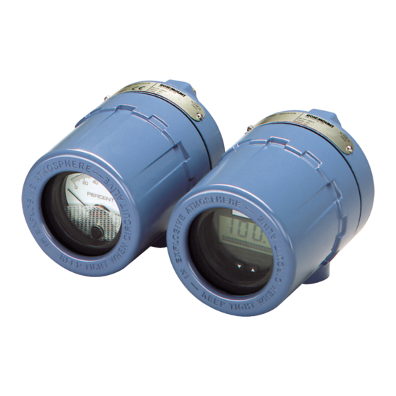
Field signal indicator
Hide thumbs
Also See for Rosemount 751:
- Quick start manual (28 pages) ,
- Reference manual (16 pages) ,
- Quick start manual (24 pages)

Related Manuals for Emerson Rosemount 751


Summary of Contents for Emerson Rosemount 751
- Page 1 Reference Manual 00809-0100-4378, Rev CF May 2022 ™ Rosemount 751 Field Signal Indicator...
- Page 2 Read this manual before working with the product. For personal and system safety, and for optimum product performance, ensure you thoroughly understand the contents before installing, using, or maintaining this product. For equipment and service needs, contact your local Emerson representative or go to Emerson.com. CAUTION The products described in this document are NOT designed for nuclear-qualified applications.
-
Page 3: Table Of Contents
Chapter 1 Introduction......................5 1.1 Product overview.........................5 1.2 LCD display..........................5 1.3 Service support..........................6 1.4 Product recycling/disposal......................6 Chapter 2 Installation.........................7 2.1 Assembly............................. 7 2.2 Wiring diagrams.......................... 8 2.3 LCD display configuration......................12 Chapter 3 Ordering information, specifications, and drawings..........17 Emerson.com/Rosemount... - Page 4 Contents Reference Manual May 2022 00809-0100-4378 Emerson.com/Rosemount...
-
Page 5: Chapter 1 Introduction
May 2022 Introduction Product overview The Rosemount 751 Field Signal Signal Indicators provide a means of displaying important process variables. These devices operate with any two-wire transmitter that measures input variables such as pressure, flow, liquid level, or temperature. Rosemount indicators are ideal for installations where an integral meter would be difficult to view. -
Page 6: Service Support
Returned products must include a copy of the required Safety Data Sheet (SDS) for each substance. Emerson representatives will explain the additional information and procedures necessary to return goods exposed to hazardous substances. -
Page 7: Chapter 2 Installation
May 2022 Installation Assembly The Rosemount 751 Field Signal Indicator is comprised of the components shown in Figure 2-1. The housing may contain an analog or liquid crystal display (LCD) display meter. Both meters are independent of component parts and are completely interchangeable. -
Page 8: Wiring Diagrams
J. Foam spacer K. Configuration buttons Wiring diagrams Use the following wiring diagrams to wire the Rosemount 751 Field Signal Indicator, in series or in parallel, with Rosemount transmitters. Use shielded cable for best results in electrically noisy environments. Emerson.com/Rosemount... - Page 9 May 2022 Series configuration It is recommended that the Rosemount 751 Indicator be wired in a series configuration when the 4-20 mA transmitter does not contain a test terminal. The indicator is designed so the analog or LCD display meter can be removed from the housing without impacting the integrity of the 4-20 mA loop.
- Page 10 Installation Reference Manual May 2022 00809-0100-4378 Figure 2-4: Rosemount 751 Series Wiring Diagrams for Rosemount 3051C and 3051S 4–20 mA dc Input Signal for Rosemount 3144P 4–20 dc Input Signal for Rosemount 2051 + − + − 3051S − 3051C −...
- Page 11 A parallel configuration will allow the removal of the indicator without affecting the integrity of the 4-20 mA loop. Additionally, spare indicators can be added without disrupting the loop. Figure 2-5: Rosemount 751 Parallel Wiring Diagrams for Rosemont 3144P and 2051 2051 3144P 4–20 mA dc Input Signal for Rosemount 3051C...
-
Page 12: Lcd Display Configuration
Installation Reference Manual May 2022 00809-0100-4378 Figure 2-6: Rosemount 751 Parallel Wiring Diagrams for Rosemount 3051C and 3051S 4–20 mA dc Input Signal for Rosemount 3144P 4–20 dc Input Signal for Rosemount 2051 3051C 3051S 4–20 mA dc Input Signal for Rosemount 3051C 4–20 dc Input Signal for Rosemount 3051S... - Page 13 Relationship between Input Signal and Digital Display Linear LinF Linear with 5-second filter Square root SrtF Square root with 5-second filter Square root function only relates to the digital display. The bar graph output remains linear with the current signal. Emerson.com/Rosemount...
- Page 14 Set the numbers between –999 and 9999. Note The sum of the 4 mA point and the span must not exceed 9999. 3. To store the information, simultaneously press both configuration buttons for two seconds. The LCD display meter is now configured. Emerson.com/Rosemount...
- Page 15 Reference Manual Installation 00809-0100-4378 May 2022 2.3.6 Replace the cover Procedure Make sure the rubber gasket is seated properly, and thread the transparent housing cover onto the LCD display meter body. Emerson.com/Rosemount...
- Page 16 Installation Reference Manual May 2022 00809-0100-4378 Emerson.com/Rosemount...
-
Page 17: Ordering Information, Specifications, And Drawings
Reference Manual Ordering information, specifications, and drawings 00809-0100-4378 May 2022 Ordering information, specifications, and drawings To view current Rosemount 751 ordering information, specifications, and drawings, follow these steps: Procedure 1. Go to Emerson.com/Rosemount/Rosemount 751 Field Signal Indicator. 2. Scroll as needed to the green menu bar and click Documents & Drawings. - Page 18 2022 Emerson. All rights reserved. Emerson Terms and Conditions of Sale are available upon request. The Emerson logo is a trademark and service mark of Emerson Electric Co. Rosemount is a mark of one of the Emerson family of companies. All other marks are the property...
Need help?
Do you have a question about the Rosemount 751 and is the answer not in the manual?
Questions and answers
Is there any way to make a Rosemont 751 read in inches. We have a 5408 level tranmitter that it is connected to that is configured for inches but i just get a percentage on the 751