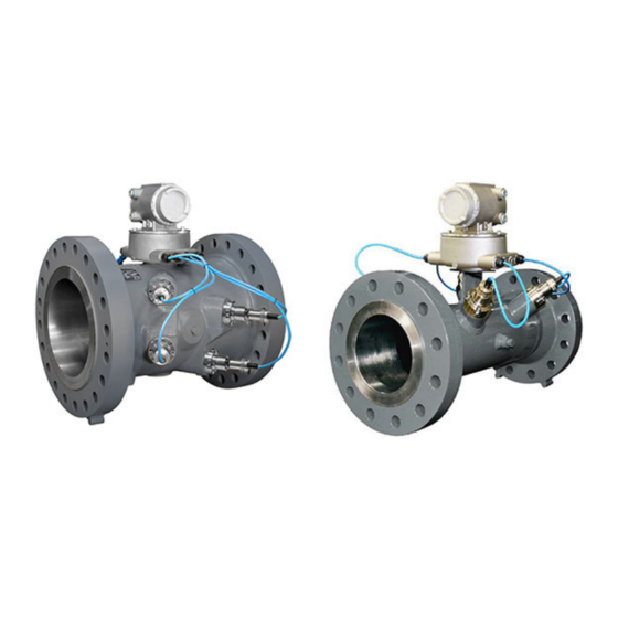
Emerson Rosemount 3410 Series Quick Start Manual
Local display field install kit
Hide thumbs
Also See for Rosemount 3410 Series:
- Reference manual (116 pages) ,
- Installation manual (106 pages) ,
- Maintenance and troubleshooting manual (96 pages)
Summary of Contents for Emerson Rosemount 3410 Series
- Page 1 Quick Start Guide 00825-0100-3104, Rev AA June 2022 3410/3810 Series Local Display Field Install Kit...
- Page 2 For hazardous installations in Europe, refer to standard EN 60079-14 if national standards do not apply. Other information Full product specifications can be found in the product data sheet. Troubleshooting information can be found in the user manual. Product data sheets and manuals are available from the Emerson website at http://www.emerson.com. Return policy Follow Emerson procedures when returning equipment.
- Page 3 February 2022 Quick Start Guide North and South America Europe and Middle East Asia Pacific 800 0444 0684 Quick Start Guide...
- Page 4 Quick Start Guide February 2022 Signal words and symbol Pay special attention to the following signal words, safety alert symbols and statements: Safety alert symbol This is a safety alert symbol. It is used to alert you to potential physical injury hazards. Obey all safety messages that follow this symbol to avoid possible injury or death.
-
Page 5: Component Disassembly
February 2022 Quick Start Guide Component disassembly Local display field install kit includes A. LCD display board B. LCD display shroud C. Pan HD screw PH SEMS #6-32 X .38 M/S W/410 EXT 18-8 SST D. LCD module E. Cover – HSG LCD type FB100 F. - Page 6 Quick Start Guide February 2022 Item Quantity Description LCD display board LCD display shroud Pan HD screw PH SEMS #6-32 X .38 M/S W/410 EXT 18-8 SST LCD module Preassembled: Cover – HSG LCD type FB100 O-ring #2-245 Backplane board 3410/3810 Pan HD screw PH SEMS #6-32 X .88 Item numbers correlate with DMC-009079 - 3410/3810 Series LCD Module Check firmware version before powering off the meter...
- Page 7 — Open MeterLink and connect to the meter — Open an Internet browser — Navigate to the Emerson website: emerson.com/Rosemount — Use Quick Links and click MeterLink Registration and Download to access the latest firmware — Go to MeterLink and use the Tools|Program Download menu to download a file to the meter.
- Page 8 Quick Start Guide February 2022 A. CPU TB-2 B. CPU TB-1 C. I/O module connectors D. 24V loop power E. 10.4VDC - 36VDC power Remove the backplane board A. Backplane board B. I.S. barrier board C. Power supply board • Remove four screws with lock washers.
- Page 9 February 2022 Quick Start Guide Disconnect the acquisition cable A. Acquisition cable Quick Start Guide...
-
Page 10: Component Assembly
Quick Start Guide February 2022 Component assembly Backplane board with 14 pin connector A. 14 pin connector B. Backplane board Note Check existing 3410/3810 Series Backplane board minimum for 14 pin connector (J8). If equipped, use this board. If not, use board included with the Local Display Field Install Kit. - Page 11 February 2022 Quick Start Guide Plug power supply board and I.S. barrier module onto backplane board with 14 pin connector A. I.S. barrier board B. Backplane board C. Power supply board Plug local display board into the backplane 14 pin connector A.
- Page 12 Quick Start Guide February 2022 Slide backplane, power supply, I.S. barrier module and local display module assembly into transmitter enclosure and fasten with 4 pan head screws. • Make sure boards are aligned in the enclosure and I.S. barrier board is inside card cage key retainer.
- Page 13 February 2022 Quick Start Guide Reinstall CPU module and I/O module in the enclosure Install CPU module TB-1 and TB-2 and I/O module terminal connectors A. CPU TB-2 B. CPU TB-1 C. I/O module connectors Quick Start Guide...
- Page 14 Quick Start Guide February 2022 If explosive atmosphere is not present, connect the power supply terminal connectors and apply power to the unit A. 24V loop power B. 10.4VDC - 36VDC power • Ensure all CPU LEDs are green A. CPU LEDs •...
- Page 15 February 2022 Quick Start Guide If explosive atmosphere is present, install endcaps and apply site power to equipment A. Endcap security latch • Reinstall endcap security latches • Apply site power Note If explosive atmosphere is present and site power initializes the unit, a Service technician should observe the Local Display startup sequence (see Observe local display startup sequence).
- Page 16 Quick Start Guide February 2022 • Make sure all segments are displayed (all the segments will come on and stay on for about 4 seconds). Pay careful attention and make sure that all segments are functioning and no segments are missing. •...
- Page 17 February 2022 Quick Start Guide 2.12 Reinstall wire security seals on the endcaps, if necessary Installation complete A. 3410/3810 series transmitter with local display Quick Start Guide...
- Page 18 Quick Start Guide February 2022 Local Display Field Install Kit...
- Page 19 February 2022 Quick Start Guide Quick Start Guide...
- Page 20 2022 Emerson. All rights reserved. Unauthorized duplication in whole or part is prohibited. Printed in the USA. The Emerson logo is a trademark and service mark of Emerson Electric Co. All other trademarks are the property of their respective companies.


Need help?
Do you have a question about the Rosemount 3410 Series and is the answer not in the manual?
Questions and answers