Table of Contents
Advertisement
Quick Links
Advertisement
Table of Contents

Subscribe to Our Youtube Channel
Related Manuals for Infranor Gem Drive GD1 Series


Summary of Contents for Infranor Gem Drive GD1 Series
- Page 1 Gem Drive Installation Guide Actuator INFRANOR...
- Page 2 This symbol indicates that INFRANOR devices must be eliminated by selective disposal and not with standard waste. INFRANOR does not assume any responsibility for any physical or material damage due to improper handling or wrong descriptions of the ordered items.
-
Page 3: Table Of Contents
GD1 – Installation Guide General content Page CONTENT PART 1 ..........................5 CHAPTER 1 – GENERAL DESCRIPTION..................... 7 1.1 - INTRODUCTION......................... 7 1.2 - HARDWARE ARCHITECTURE TYPES..................8 1.2.1 - Single-axis configuration ..................... 8 1.2.2 - Multiaxis configuration ......................9 1.3 - COMMUNICATION INTERFACES ................... - Page 4 GD1 – Installation Guide CHAPTER 4 – CONNECTIONS......................30 4.1 - CONNECTION DIAGRAM OF GD1 – STAND-ALONE 230 V OR 400 V ......30 4.2 - CONNECTION OF THE SERIAL LINK RS-232................. 31 4.3 - CONNECTION OF A BACKUP BATTERY ................31 4.4 - WIRING RECOMMENDATIONS....................
- Page 5 GD1 – Installation Guide PART 1 ________ AMPLIFIER Part 1 – GD1 amplifier...
-
Page 6: Content Part 1
GD1 – Installation Guide Content Part 1 Page CONTENT PART 1 ..........................5 CHAPTER 1 – GENERAL DESCRIPTION..................... 7 1.1 - INTRODUCTION......................... 7 1.2 - HARDWARE ARCHITECTURE TYPES..................8 1.2.1 - Single-axis configuration ..................... 8 1.2.2 - Multiaxis configuration ......................9 1.3 - COMMUNICATION INTERFACES ................... - Page 7 GD1 – Installation Guide CHAPTER 4 - CONNECTIONS ......................30 4.1 - CONNECTION DIAGRAM OF GD1 – STAND-ALONE 230 V OR 400 V ......30 4.2 - CONNECTION OF THE SERIAL LINK RS-232................. 31 4.3 - CONNECTION OF A BACKUP BATTERY ................31 4.4 - WIRING RECOMMENDATIONS....................
-
Page 8: Chapter 1 - General Description
GD1 – Installation Guide Chapter 1 – General description 1.1 – INTRODUCTION GD1 all-digital drives with sinusoidal PWM control are servo drives that provide the control of brushless AC motors with a sensor (resolver, encoder or, as an option, second encoder sensor on the load). Several versions are available: ♦... -
Page 9: Hardware Architecture Types
GD1 – Installation Guide 1.2 – HARDWARE ARCHITECTURE TYPES 1.2.1 – S INGLE AXIS CONFIGURATION INTEGRATED 230 V SINGLE-PHASE POWER SUPPLY UNIT RATED POWER < 4 kW Power supply filtre braking resistor GD1- 230/05 to 30 - PS-R * GD1-230/05 and 08 without braking resistor. INTEGRATED 400/480 V THREE-PHASE POWER SUPPLY UNIT RATED POWER <... -
Page 10: Multiaxis Configuration
GD1 – Installation Guide 1.2.2 – M ULTIAXIS CONFIGURATION MULTIAXIS CONFIGURATION WITH INTEGRATED 230 V SINGLE-PHASE POWER SUPPLY UP TO A RATED POWER < 4 kW (n max = 6) Power supply filtre braking resistor DC bus 320 V GD1- 230/05 to 20 - 00-0 GD1- 230/05 to 30 - PS-R Connect the actuators from A1 to An in the decreasing order of their current ratings... - Page 11 GD1 – Installation Guide MULTIAXIS CONFIGURATION WITH EXTERNAL POWER SUPPLY UNIT: GDPS-400/xx The external GDPS power supply must be connected to the three-phase mains. Its operating range is between 230 V and 480 V POWER SUPPLY SOURCE: 230 V THREE-PHASE When connected to a 230 V three-phase power supply source, it provides a 320 V DC Bus voltage compliant...
-
Page 12: Communication Interfaces
GD1 – Installation Guide CALCULATION OF THE AVERAGE RATED POWER OF THE APPLICATION: see section 4.9.2 1.3 – COMMUNICATION INTERFACES The standard version of the GD1 is delivered with the CANopen communication interface. But this drive is also available with other interfaces. 1.4 –... -
Page 13: Reference To The Ce Standards
GD1 – Installation Guide 1.6.2 – R EFERENCE TO THE STANDARDS According to the Directive 2004/108/EC, the GD1 drives have been approved with regard to their compliance with the Electromagnetic Compatibility standards concerning the power servos referenced in the EN 61800-3 standard "Electrical variable speed power servo systems", Part 3: EMISSION EN 61800-3:2004 –... -
Page 14: Chapter 2 - Specifications
GD1 – Installation Guide Chapter 2 – Specifications 2.1 – MAIN TECHNICAL DATA 2.1.1 – GD1-230/I SINGLE AXIS DRIVE Mains operated power supply voltage 230 V +10% / -15% single-phase 50-60 Hz Isolated auxiliary logic supply Input voltage: 24 V +/-15% Input current: I = 320 mA without brake... -
Page 15: Gd1-400/I Single-Axis Drive
GD1 – Installation Guide 2.1.2 – GD1-400/I SINGLE AXIS DRIVE Mains operated power supply voltage 230 V -15% to 480 V +10% three-phase, TN or TT system with grounded neutral point. 50 to 60 Hz (phase-ground voltage must be balanced) IT system supported but not recommended Voltage unbalance Max. -
Page 16: Technical Features
GD1 – Installation Guide 2.1.3 – T ECHNICAL FEATURES Servo loops: current, speed and position Digital. Sampling period: Mains filter on power supply Integrated Common mode filter on auxiliary supply Integrated Common mode filter on motor brake supply Integrated Position measurement sensor Transmitter resolver Absolute single-turn encoder (ERN1085 or compliant) Incremental encoder (TTL or SinCos signals) - Page 17 GD1 – Installation Guide Optocoupled logic inputs (programmable) INX: 10 programmable inputs Analog inputs (programmable) AN1 (12 bit) AN2 (12 bit) Optocoupled logic outputs (programmable) OUTX: 4 programmable outputs VLS2 (optional safety function) VLS1 (optional safety function) Analog outputs (programmable) AN_OUT1 (8 bit) filtered PWM analog output AN_OUT2 (8 bit) filtered PWM analog output Opto-relay outputs...
-
Page 18: Dimensions
GD1 – Installation Guide 2.2 – DIMENSIONS SIDE VIEW SIDE VIEW Drive Power supply unit and small current drives I ≤ 8 A UPPER VIEW (pitch between 2 axes) FRONT SIDE FRONT SIDE Power supply Amplifiers 60 and 90 A Amplifiers up to 45 A DRILLING M4 GD1-230/05 to 08... - Page 19 GD1 – Installation Guide SINGLE-AXIS UPPER VIEW WALL-CROSSING MOUNTING (wall crossing mounting) = 68.5 = 14.5 Spacing for mounting Cabinet rear wall Slot to be cut out only if using an integrated braking resistor 14.5 2 M4 holes DOUBLE-AXIS WALL-CROSSING MOUNTING MULTIAXIS WALL-CROSSING MOUNTING 34.25...
-
Page 20: Chapter 3 - Inputs-Outputs
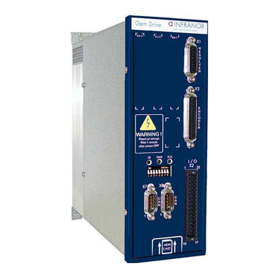
GD1 – Installation Guide Chapter 3 – Inputs-Outputs 3.1 – LOCATION OF THE GD1-uuu/cc CONNECTORS UPPER VIEW X1 Resolver X3 Encoder Address X5 Serial link X7: CAN X2 Inputs-Outputs X6: CAN BOTTOM VIEW 230 V Neutral Br - Br + A U X I L I A R Y S U P P L Y 2 4 V 400 V +24V... -
Page 21: Led Display
GD1 – Installation Guide 3.2 – LED DISPLAY 3.2.1 – I DENTIFICATION OF THE STATE DESCRIPTION ERROR LED (red) Flashing Error Error list: see GD1 User Guide "Undervolt. " Fault No fault SYS LED (green) System OK Quick flashing Firmware upgrade or OFF BUS LED (green) RUN LED CANopen... -
Page 22: X1 Connector: Resolver
GD1 – Installation Guide 3.4 – X1 CONNECTOR: RESOLVER SUB D 15 pins female Section: 4 x 2 x 0.25 mm (AWG22) twisted pairs, shielded, max. 100 m. Housing width ≤ 15,3 mm. Example: MH connectors Ref. 6260-0105-02 (width = 15 mm). Mandatory width ≤... -
Page 23: Specification Of The Logic Inputs Inx
GD1 – Installation Guide 3.5.1 – S PECIFICATION OF THE LOGIC INPUTS 3,3 V 8,2 kΩ 100 nF* Logic input 100 kΩ 0V external (*): 100 pF for Index and Capture inputs These optocoupled inputs operate in positive logic. The input voltage corresponding to level 1 must be between 18 V and 30 V. 3.5.2 –... -
Page 24: Specification Of The Logic Outputs Outx
GD1 – Installation Guide 3.5.3 – S OUTX PECIFICATION OF THE LOGIC OUTPUTS +24V external +24V external 10 kΩ 330 Ω Driver 0V external External supply +24 V (18 V < U < 30 V) Maximum voltage drop: 2 V Protection agains overload Available output current per output (mA) Number of activated outputs / Cycle ratio (%) -
Page 25: X3 Connector: Encoder
GD1 – Installation Guide 3.6 – X3 CONNECTOR: ENCODER 3.6.1 – X3 C "TTL & HES " (SUB D 25 ONNECTOR FOR INCREMENTAL ENCODER INPUT PINS FEMALE The "TTL incremental encoder & HES" configuration is software selectable and stored in the drive EEPROM. Section: 2 x 0,25 mm (AWG22) twisted pairs, shielded, max 25 m (see section... - Page 26 GD1 – Installation Guide 3.6.2 –X3 C "SIN/COS & HES " (SUB D 25 ONNECTOR FOR INCREMENTAL ENCODER INPUT PINS FEMALE The "SinCos & HES" incremental encoder configuration is software selectable and stored in the drive EEPROM. Section: 2 x 0.25 mm (AWG22) twisted pairs, shielded, max.
-
Page 27: X3 Connector For "Sin/Cos & Hes Incremental Encoder" Input (Sub D 25 Pins Female) 25 3.6.3 - X3 Connector For "Absolute Single-Turn Sin/Cos Encoder" Input (Sub D 25 Pins Female)
GD1 – Installation Guide 3.6.3 – X3 C "A SIN/COS " (SUB D 25 ONNECTOR FOR BSOLUTE SINGLE TURN ENCODER INPUT PINS FEMALE The "SinCos absolute single-turn" incremental encoder configuration (Heidenhain ERN 1085 or compliant) is software selectable and stored in the drive EEPROM. Section: 6 x 2 x 0.25 mm (AWG22) twisted pairs, shielded, max. -
Page 28: X4 Connector
GD1 – Installation Guide 3.7 – X4 CONNECTOR Connection cable between the GDPS power supply unit and the first axis drive: cable provided with the GDPS unit (see Part 2). To be connected only between the first GD1 axis and the GDPS-400/xx unit (see Part 3.8 –... -
Page 29: Connector X10: Power - Motor Output
GD1 – Installation Guide 3.12 –CONNECTOR X10: POWER – MOTOR OUTPUT 4 pins male (female connector provided). 7.62 mm pitch for current ratings ≤ 45 A. 10.16 mm pitch for current ratings > 45 A. Tightening torque of the connector screws: 0.5 to 0.6 Nm for connectors with 7.62 mm pitch 1.2 to 1.5 Nm for connectors with 10.16 m pitch SIGNAL... -
Page 30: X13 Connector: Additonnal Braking Resistor
GD1 – Installation Guide 3.14.2 – T 400 V HREE PHASE POWER INPUT CONNECTOR FOR THE SINGLE AXIS CONFIGURATION 4 pins male with 7.62 mm pitch (female connector provided). Tightening torque of the connector screws: 0.5 to 0.6 Nm. SIGNAL FUNCTION DESCRIPTION Phase L1... -
Page 31: Chapter 4 - Connections
GD1 – Installation Guide Chapter 4 – Connections 4.1 – CONNECTION DIAGRAM OF GD1 – STAND-ALONE 230 V OR 400 V GD1-uuu/cc/PS-R RESOLVER Motor temp. AOK+ (1) Motor temp. AOK- R ENABLE IN1 (ENABLE) Resolver IN2 (FC+) signal IN3 (FC-) IN4 (Index) 24 V Ext. -
Page 32: Connection Of The Serial Link Rs-232
GD1 – Installation Guide 4.2 – CONNECTION OF THE SERIAL LINK RS-232 360° shield connection Serial port Sub D 9 pins female Sub D 9 pins female REMARK: For PCs which are not equipped with the serial link RS232, RS232/USB converters must be used. But, since RS232/USB converters are generally an office equipment, they are not meant to be used in an industrial environment subjected to EMC disturbances. - Page 33 GD1 – Installation Guide Reference potential loops (especially with the ground) are recommended only if these connections have a very low impedance (<0.1 Ω). Any shield that is used as a conductor can be connected at both ends with the condition to be connected over 360°...
-
Page 34: Shield Connection On The Connectors
GD1 – Installation Guide 4.4.2 – S HIELD CONNECTION ON THE CONNECTORS RULE The shield should never be interrupted or corrupted over the whole cable length. NOTE When the 360° shield connection is made by means of a collar, it is not necessary to connect an additional cable on the pertaining pin of the SUB-D connector. -
Page 35: Motor, Resolver And Encoder Cables
GD1 – Installation Guide 4.5 – MOTOR, RESOLVER AND ENCODER CABLES Motors, resolvers and encoders are grounded via their housing. Cable inputs must be made by means of metal connectors with collars allowing the 360° shield connection. The resolver cable must be pair twisted and shielded (sin, cos, ref.). Motor cables MUST also be shielded and connected over 360°... -
Page 36: Serial Link And Can Communication Cables
GD1 – Installation Guide UNDESIRABLE EFFECTS OF MOTOR CABLES LONGER THAN 25 M ♦ Heating of the power module, the motor and the cable. ♦ High overvoltages on the motor windings involving a shortening of their life time. The reactance reduces the undesirable effects on motor and drive but it may be quite heated. This requires an appropriate fan. -
Page 37: Requirements For The Compliance With The Ul Standards
GD1 – Installation Guide 4.9 – REQUIREMENTS FOR THE COMPLIANCE WITH THE UL STANDARDS The UL listing requires the following conditions to be fulfilled by the installer of the drives. 4.9.1 – 24 V SUPPLY The end user has to provide a 24 V isolated power supply (i.e. -
Page 38: Chapter 5 - Appendix
X1 connector as well as the manufacturer's diagram: The factory-set resolver calibration allows an optimum operation for resolvers which transformation ratio is between 0.3 and 0.5. For the use of resolvers with transformation ratios out of the range 0.3 to 0.5, please contact the INFRANOR factory. NOTE When using resolvers with a number of pole pairs N >... -
Page 39: Energy Recuperation Via A Braking Resistor
GD1 – Installation Guide 5.3 – ENERGY RECUPERATION VIA A BRAKING RESISTOR All GD1 drives are equipped with the power feedback system. When the motor is decelerating with high inertia and high speed, the mechanical braking energy is reflected to the drive. This energy is dissipated inside a resistor called "braking resistor". - Page 40 GD1 – Installation Guide PART 2 GDPS ________ POWER SUPPLY Part 2 – GDPS power supply...
-
Page 41: Content Part 2
GD1 – Installation Guide Content Part 2 Page CHAPTER 1 - SPECIFICATIONS......................41 1.1 - INTRODUCTION........................41 1.2 - MULTIAXIS POWER SUPPLY UNIT GDPS-400/16-32 ............41 CHAPTER 2 - CONNECTORS ......................43 2.1 - LOCATION OF THE GDPS CONNECTORS................43 2.2 - J1 CONNECTOR: THREE-PHASE 400 V POWER INPUT FOR THE CONFIGURATION WITH EXTERNAL POWER SUPPLY UNIT (GDPS) ................... -
Page 42: Chapter 1 - Specifications
GD1 – Installation Guide Chapter 1 - Specifications 1.1– INTRODUCTION The external GDPS-400/xx power supply unit is the power supply for the GD1 actuators which power required for the application is higher than 4 kW in 230 V or 7 kW in 400/480 V GD1 actuators using the external GDPS power supply are not equipped with an integrated power supply (GD1- uuu/cc/00-0). - Page 43 GD1 – Installation Guide Low level link cable between the GDPS power supply unit and the first axis supplied with the GDPS power supply unit and to be connected to the first axis. The polarity DC+ with DC+ and DC- with DC- between the GD1-uuu/cc drives and the GDPS power supply unit must be observed.
-
Page 44: Chapter 2 - Connectors
GD1 – Installation Guide Chapter 2 - Connectors 2.1 – LOCATION OF THE GDPS CONNECTORS CONNECTION OF GDPS BRAKING RESISTOR BOTTOM VIEW DC BUS 400 VAC MAINS Part 2 – Chapter 2 - Connectors... -
Page 45: J1 Connector: Three-Phase 400 V Power Input For The Configuration With External Power Supply Unit (Gdps)
GD1 – Installation Guide 2.2 – J1 CONNECTOR: THREE-PHASE 400 V POWER INPUT FOR THE CONFIGURATION WITH EXTERNAL POWER SUPPLY UNIT (GDPS) External power supply unit GDPS-400/cc 4 pins male with 10.16 mm pitch (female connector provided) Tightening torque of the connector screws: 1.2 to 1.5 Nm SIGNAL FUNCTION DESCRIPTION... -
Page 46: Chapter 3 - Connexions
GD1 – Installation Guide Chapter 3 – Connexions 3.1 – CONNEXION DIAGRAM OF THE SUPPLIES IN MULTIAXIS CONFIGURATION WITH GDPS 400/XX POWER SUPPLY UNIT This connection type is required when the installation rated power of the application is higher than 7 kW in 400 V Part 2 –... -
Page 47: Power Supply And Ul Fuse Rating
GD1 – Installation Guide 3.2 – POWER SUPPLY AND UL FUSE RATING For the GDPS-400/xx multiaxis power supply unit: GDPS 400/16 400/32 FERRAZ A60Q20-2 A60Q40-2 Part 2 – Chapter 3 - Connexions... -
Page 48: Chapter 4 - Order Code
GD1 – Installation Guide Chapter 4 – Order code 4.1 – ORDER CODE GDPS – 400 / xx Voltage: 400 V Rated power: 16 or 32 kW 4.2 – ACCESSORIES BRAKING RESISTOR dp 50/200 (50 Ω/200 W) braking resistor external braking resistor on GD1-230/cc with internal power supply if 200 Ω/65 W integrated braking resistor is not enough (to be connected on X3) dp 33/280 (33 Ω/280 W) braking resistor for GDPS-16... - Page 49 GD1 – Installation Guide PART 3 APPENDIX ________ Part 2 – Chapter 4 – Order code...
-
Page 50: Content Part 3
GD1 – Installation Guide Content Part 3 Page 1 - OPERATING ENVIRONMENT CONDITIONS................. 50 2 - "SAFE TORQUE OFF" OPTION..................... 53 2.1 - DESCRIPTION.......................... 53 2.2 - RECOMMENDATIONS FOR THE INTEGRATION ..............53 2.2.1 - SAFETY INSTRUCTIONS....................53 2.2.2 - STO CONNECTION ......................54 2.2.3 - TIMINGS.......................... -
Page 51: Operating Environment Conditions
The drive must be mounted indoor, on a stiff surface, in rooms or additional housings without hindering the heatsink and the fan. The liability may be increased by installing a cooling system. Other installation conditions must be specifically analysed and be subjected to a technical specification agreed by INFRANOR. Mechanical mounting There are two possible mountings:... - Page 52 GD1 – Installation Guide UNUSUAL OPERATING ENVIRONMENT CONDITIONS The use of the power converter, its pertaining control system and of the servo in conditions which are diverging from the usual ones defined by the IEC 60146-1-1 standard must be considered as abnormal. These abnormal operation conditions must be specified by the purchaser.
- Page 53 GD1 – Installation Guide TRANSPORT 1 - Climatic conditions The equipment can be transported in its standard package in the environment conditions specified by class 2K3 of the IEC 60721-3-2. This includes: Room temperature: -25°C to +70°C NOTE: The room temperature is the temperature which is the nearest to the equipment, i.e. the inside of the container.
-
Page 54: Safe Torque Off" Option
GD1 – Installation Guide 2 – "SAFE TORQUE OFF" OPTION 2.1- DESCRIPTION Safe Torque Off (STO) definition according to the EN 61800-5-2 standard: "Power, that can cause rotation (or motion in the case of a linear motor), is not applied to the motor. The drive will not provide energy to the motor which can generate torque (or force in the case of a linear motor)'. -
Page 55: Sto Connection
GD1 – Installation Guide 2.2.2 – STO CONNECTION X2 N° SIGNAL FUNCTION DESCRIPTION STO1 Channel 1 for the STO function inhibition 24 Vdc releases the enabling STO2 Channel 2 for the STO function inhibition 24 Vdc releases the enabling 0 V internal GND internal Voltage reference of the STO1 and 2 inputs. - Page 56 GD1 – Installation Guide When using high inertia or low resistive torque machines, the user should initiate a controlled stop. To achieve a controlled stop in accordance with stop category 1 of the EN60204-1 standard, the control system of the machine must generate the following sequences: deceleration of the load by means of the drive, when the load is at standstill or almost, shutting down of the PWM by disabling the "enable/inhibit signal"...
Need help?
Do you have a question about the Gem Drive GD1 Series and is the answer not in the manual?
Questions and answers