Table of Contents
Advertisement
Quick Links
Advertisement
Table of Contents

Related Manuals for Infranor XtrapulsCD1-a Series


Summary of Contents for Infranor XtrapulsCD1-a Series
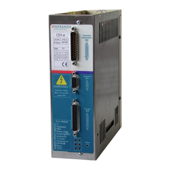
- Page 1 XtrapulsCD1-a Digital drive for AC sinusoidal brushless motors...
- Page 2 This symbol indicates that INFRANOR devices must be eliminated by selective disposal and not with household waste. INFRANOR does not assume any responsibility for physical or material damage due to improper handling or wrong descriptions of the ordered items. Any service on the items, which is not specified in the manual, will immediately cancel the warranty.
-
Page 3: Table Of Contents
XtrapulsCD1-a Content PAGE CONTENT ............................... 3 CHAPTER 1 - GENERAL DESCRIPTION ..................... 6 1- INTRODUCTION..........................6 2 - DESCRIPTION / COMPLIANCE WITH THE STANDARDS ............6 2.1 - GENERAL DESCRIPTION ....................... 6 2.2 - REFERENCE TO THE STANDARDS: "CE" CERTIFICATION ..........7 2.3 - REFERENCE TO THE STANDARDS: "UL"... - Page 4 XtrapulsCD1-a 4.3 - X3 CONNECTOR FOR ABSOLUTE SINGLE-TURN SinCos ENCODER (Sub D 25 pins female) ............................23 4.4 - X3 CONNECTOR FOR STEPPER MOTOR EMULATION (Sub D 25 pins female) ....24 5 - X5 SERIAL LINK (Sub D 9 pins male) ..................25 6 - X8: AUXILIARY SUPPLY CONNECTOR ..................
- Page 5 XtrapulsCD1-a 1.9 - "FEEDBACK" FAULT IN THE ENCODER FEEDBACK CONFIGURATION ......46 1.10 - "COUNTING" FAULT IN THE ENCODER FEEDBACK CONFIGURATION ....... 46 1.11 - "HES" FAULT ........................47 1.12 - "I T" FAULT .......................... 48 1.13 - FOLLOWING ERROR ......................48 2 - OPERATING PROBLEMS ......................
-
Page 6: Chapter 1 - General Description
XtrapulsCD1-a Chapter 1 - General description 1- INTRODUCTION Series XtrapulsCD1-a all-digital servo modules are PWM servo drives that provide speed control for AC sinusoidal motors (brushless) equipped with a position sensor. The XtrapulsCD1-a system is available as a stand-alone single-axis block including all supplies as well as the mains filters, and is 230 VAC or 400/480 VAC mains operated. -
Page 7: Reference To The Standards: "Ce" Certification
Standard to be applied to the electrical equipments of industrial machines: EN 60204.1. 2.3 - REFERENCE TO THE STANDARDS: "UL" LISTING XtrapulsCD1-a series have been « » listed according to UL508C and UL840 regarding the insulator. This product was evaluated to:... -
Page 8: Chapter 2 - Specifications
XtrapulsCD1-a Chapter 2 - Specifications 1 - TECHNICAL SPECIFICATIONS 1.1 – XTRAPULS CD1-a-230/I DRIVE Mains operating power supply 230 VAC +10 % / -15 %, 1~ or 3~, 50 - 60 Hz Isolated galvanic auxiliary supply voltage 24 VDC +/- 15 % - 320 mA Motor phase-phase output voltage 200 Vrms Integrated braking system... -
Page 9: Common Specifications To Both Drive Versions Xtrapuls Cd1-A-230/I And Xtrapuls Cd1-A-400/I
XtrapulsCD1-a DRIVE OUTPUT CURRENT RATINGS Output voltage range for 400-480 VAC (rms) three-phase mains. Output current range: 1.8 A, 2.7 A, 5.1 A, 7.2 A, 14 A, 30 A, 45 A, 70 A, 90 A (rms) Max. protection Max. output Rated Rated input fuses for line... - Page 10 XtrapulsCD1-a Max. motor speed Adjustable from 100 rpm to 25000 rpm Speed range 1 : 8192 with 14 bits input command resolution Encoder position output Two A and B channels in quadrature with 1 marker pulse per revolution. RS422 line driver. Programmable resolution between 64 ppr and 16384 ppr (according to the motor maximum speed) Arc minute accuracy = (8 + 5400/Resolution)
- Page 11 Electrical standards for industrial machines: mains filter. - EN 60204.1: - Insulator: 1500 VAC/1 min. - Leakage current > 30 mA (EMI filters) XtrapulsCD1-a series have been “ ” listed according to Compliance with the standards: listing UL508C and UL840 regarding the insulator.
-
Page 12: Block Diagram
XtrapulsCD1-a 2 - BLOCK DIAGRAM Chapter 2 – Specifications... -
Page 13: Main Protections
XtrapulsCD1-a 3 - MAIN PROTECTIONS 3.1 - STORED PROTECTIONS PROTECTION ERROR DISPLAY Drive rated current overload (see Chapter 8, part 3.2) Position feedback cable interruption (resolver or encoder) Feedback Hall Effect Sensors sequence error or cable interruption / ... -
Page 14: Dimensions
XtrapulsCD1-a 4 - DIMENSIONS 4.1 - XTRAPULS CD1-a-230/I 4.2 - XTRAPULS CD1-a-400/1,8 TO 7,2 A 4.3 - XTRAPULS CD1-a-400/14 4.4 - XTRAPULS CD1-a-400/30/45/70 AND 90 A Chapter 2 – Specifications... -
Page 15: Braking Resistors Dp 100/100, Dp 200/100, Dp 50/200, Dp 33/280 And Dp 16.5/560
XtrapulsCD1-a 4.5 - BRAKING RESISTORS dp 100/100, dp 200/100, dp 50/200, dp 33/280 AND dp 16.5/560 dp 16.5/560 Connection of the braking resistor dp 16.5/560 on pins 1 and 3 of the braking resistor connector DIMENSIONS dp 50/200, dp 100/100 and dp dp 33/280 dp 16.5/560 200/100... -
Page 16: Fastening
XtrapulsCD1-a 5 - FASTENING VERTICAL MOUNTING IS MANDATORY 5.1 - XTRAPULS CD1-a-230/I 5.2 - XTRAPULS CD1-a-400/1.8 TO 7.2 A 5.3 - XTRAPULS CD1-a-400/14 5.4 - XTRAPULS CD1-a-400/30/45/70 AND 90 A Chapter 2 – Specifications... -
Page 17: Multiaxes Cabinet Mounting
XtrapulsCD1-a 6 – MULTIAXES CABINET MOUNTING 6.1 - XTRAPULS CD1-a-230/I 6.2 - XTRAPULS CD1-a-400/1.8 TO 7.2 A 6.3 - XTRAPULS CD1-a-400/14 6.4 - XTRAPULS CD1-a-400/30/45/70 AND 90 A Chapter 2 - Specifications... -
Page 18: Chapter 3 - Inputs-Outputs
XtrapulsCD1-a Chapter 3 - Inputs-Outputs 1 - CONNECTORS LOCATION 1.1 - DRIVE CONNECTORS 2 - X1: RESOLVER CONNECTOR (Sub D 9 pins female) Same connector for both 230 V and 400 V ranges. FUNCTION REMARKS TC (thermal sensor) If thermal switch connected to X1 Shield connection The shield must have a 360°... -
Page 19: X2: Command Connector, Logic Inputs-Outputs And Encoder (Subd 25 Pins Male )
XtrapulsCD1-a 3 – X2: COMMAND CONNECTOR, LOGIC INPUTS-OUTPUTS AND ENCODER (Sub D 25 pins male) Same connector for both 230 V and 400 V ranges. Function I / O REMARKS FC+: Limit switch + Positive logic, optocoupled input, galvanic insulation FC-: Limit switch - Positive logic, optocoupled input, galvanic insulation Ref. -
Page 20: Specification Of The Analog Inputs: Cv+, Cv-, Ilim
XtrapulsCD1-a 3.1 - SPECIFICATION OF THE ANALOG INPUTS: CV+, CV-, Ilim X2-17 (CV+) 100K 100K 100K 100K X2-16 (CV-) X2-15 (GND) 2.2nF X2-3 (ILIM) 100K X2-25 (GND) 3.2 - SPECIFICATION OF THE LOGIC OPTOCOUPLED INPUTS: ENABLE, FCP, FCN, RESET, CVO, CI 8.2 k... -
Page 21: Specification Of The Encoder Outputs
XtrapulsCD1-a 3.4 - SPECIFICATION OF THE ENCODER OUTPUTS Recommended receiver: 26LS32 3.5 - SPECIFICATION OF THE ANALOG OUTPUT 4.7nF 200K X2/11 X2/25 4 - X3 ENCODER INPUT Same connector for both 230 V and 400 V ranges. 4.1 - X3 CONNECTOR FOR TTL INCREMENTAL ENCODER & HES INPUT (Sub D 25 pins female) The “TTL incremental encoder &... -
Page 22: X3 Connector For Sincos Incremental Encoder & Hes Input (Sub D 25 Pins Female)
XtrapulsCD1-a ENCODER INPUT LINES SPECIFICATION 3.3K Receiver 75-176 Receiver X3- 5 200R 200R 75-176 X3- 6,7 470R X3- 18 X3- 19,20 (*)The 470 resistor is wired as from index: 400/1.8 to 7.2 A 400/14 A 400/30 to 45 A 400/70 to 90 A XtrapulsCD1-a N... -
Page 23: X3 Connector For Absolute Single-Turn Sincos Encoder (Sub D 25 Pins Female)
XtrapulsCD1-a (1): The sum of the currents consumed by both X2 connector, pin 21, and X3 connector, pin 10, must not exceed 150 mA. SIN/COS ENCODER CHANNELS SPECIFICATION X3-1,2,13 120R X3-14,15,25 Uref HALL SENSORS INPUT LINES SPECIFICATION +3.3V X3-11,12,24 74HC14 X3-23 4.3 - X3 CONNECTOR FOR ABSOLUTE SINGLE-TURN SinCos ENCODER (Sub D 25 pins female) The “... -
Page 24: X3 Connector For Stepper Motor Emulation (Sub D 25 Pins Female)
XtrapulsCD1-a SIN/COS ENCODER CHANNELS SPECIFICATION X3-1,2,13 120R X3-14,15,25 Uref SIN/COS COMMUTATION CHANNELS SPECIFICATION X3-3,4 X3-16,17 Uref 4.4 - X3 CONNECTOR FOR STEPPER MOTOR EMULATION (Sub D 25 pins female) The "Stepper motor emulation" is software configurable and stored in the drive EEPROM. The corresponding X3 connector pin functions are described below. -
Page 25: X5 Serial Link (Sub D 9 Pins Male)
XtrapulsCD1-a 5 - X5 SERIAL LINK (Sub D 9 pins male) Same connector for both 230 V and 400 V ranges. FUNCTION REMARKS 0 Volt GND (connection of the shield if no "360°" connection on the connector) Transmit data RS-232 Receive data RS-232 Transmit data RS-422 Transmit data RS-422... -
Page 26: Chapter 4 - Connections
XtrapulsCD1-a Chapter 4 - Connections 1 - CONNECTION DIAGRAMS 1.1 – XTRAPULS CD1-a-230/I DRIVE (For the UL certified connection, see chapter 4, section 3.4). The protection, on source side, of both 24 V and power supplies must be made by the user. Chapter 4 –... -
Page 27: Xtrapuls Cd1-A-400/I Drive
XtrapulsCD1-a 1.2 – XTRAPULS CD1-a-400/I DRIVE (See chapter 4, section 3.5 for the UL compliant connection). The protection, on source side, of both 24 V and power supplies must be made by the user. 1.3 - SERIAL LINK CONNECTION 360° shield connection RxD 2 3 TxD CD1-a... -
Page 28: Connection Of A Backup Battery For The 24 Vdc Auxiliary Supply
XtrapulsCD1-a 1.4 - CONNECTION OF A BACKUP BATTERY FOR THE 24 VDC AUXILIARY SUPPLY The XtrapulsCD1-a drive consumption is 320 mA with 24V . So, a 24 V / 30 A/h battery can keep the drive on during i.e. a long 3 days week-end or during a mains cut-off without losing the machine initialization. This backup method is very interesting for saving the machine initialization as well as the axis position even when moving with the mains switched off. -
Page 29: Wiring
XtrapulsCD1-a 2 - WIRING (according to EN61000.4-2-3-4-5 and EN55011 standards - see diagram "Shield connection on the connectors " – chapter 4, section 2.2). 2.1 - GROUND WIRING AND LEAKAGE CURRENT CAUTION ! Each potential conducting element must be shielded. Several potential conductors in the same sleeve must be twisted and shielded. -
Page 30: Connectors Shield Connection
XtrapulsCD1-a 2.2 - CONNECTORS SHIELD CONNECTION RULE The shield should never be interrupted or corrupted over the whole cable length. NOTE When the 360° shield connection is made by means of a collar, it is not necessary to connect a cable on the appropriate pin of the SUB-D connector. -
Page 31: Connection View Of Xtrapuls Cd1-A-400/30 To 90 A
XtrapulsCD1-a 2.3 - CONNECTION VIEW OF XTRAPULS CD1-a-400/30 TO 90 A Maximum tightening torque of the ground connection: 3.6 Nm. 2.4 – MOTOR, RESOLVER AND ENCODER CABLES Motors, resolvers and encoders are grounded via their housing. Cable inputs must be made by means of metal connectors with collars allowing the 360° shield connection. The resolver cable must be pair twisted and shielded (sin, cos, ref.). -
Page 32: Input Command And Serial Link Cables
XtrapulsCD1-a Example The application requires an Heidenhain linear encoder supplied by 5 V ±5 % / 300 mA with 25 m cable length. Min. power voltage: 5 V ±5 % U = 0.25 V . Min. cross section: S = 1.2 mm². Such a large cross section is difficult to obtain, so the user can: ... -
Page 33: Requirements Of Compliance With The Ul Standards
XtrapulsCD1-a 3 - REQUIREMENTS OF COMPLIANCE WITH THE UL STANDARDS This UL listing requires some conditions to be fulfilled by the installer of the drives. 3.1 - CONNECTION BY MEANS OF FASTON SOCKET The installer must use a UL listed quick connect for ground connections (0.250 inches or 6.35 mm wide nominal) on all drives equipped with FASTON sockets. -
Page 34: Xtrapuls Cd1-A-230/I Drive: Connection Diagram With Protections By "Ul" Fuses
XtrapulsCD1-a 3.4 – XTRAPULS CD1-a-230/I DRIVE: CONNECTION DIAGRAM WITH PROTECTIONS BY "UL" FUSES (according to the table in section 3.3 of this chapter) IMPORTANT The installer of the drives has to use a UL listed quick connect for ground connection (0.250 inches or 6.35 mm wide nominal). -
Page 35: Xtrapuls Cd1-A-400/I Drive: Connection Diagram With Protections By "Ul" Fuses
XtrapulsCD1-a 3.5 – XTRAPULS CD1-a-400/I DRIVE: CONNECTION DIAGRAM WITH PROTECTIONS BY "UL" FUSES (according to the table in section 3.3 of this chapter) IMPORTANT The installer of the drives has to use a UL listed quick connect for ground connection (0.250 inches or 6.35 mm wide nominal). -
Page 36: Connection Example For A Ul Compliant Multiaxis Application
XtrapulsCD1-a 3.6 - CONNECTION EXAMPLE FOR A UL COMPLIANT MULTIAXIS APPLICATION Chapter 4 – Connections... -
Page 37: Chapter 5 - Parameter Setting
The parameter setting software VISUAL DRIVE SETUP, which is PC compatible with the WINDOWS® operating system, allows an easy modification of all drive parameters. Please, see website www.infranor.com for downloading the VISUAL DRIVE SETUP software. WARNING The auto-tuning procedure should be executed by the PC in control mode and at standstill. If the auto-tuning procedure must be executed with the drive controlled by the analog command input CV, the value of the input command MUST be 0 Volt. -
Page 38: Chapter 6 - Commissioning
XtrapulsCD1-a Chapter 6 – Commissioning 1 - DRIVE STANDARD CONFIGURATION The XtrapulsCD1-a drive hardware configuration is made for MAVILOR motors. Resolver ratio: 0.5. See Chapter 8, parts 2, 3 and 4 for the drive adjustment to other motor or resolver types. 2 - FIRST POWERING OF THE XTRAPULS CD1-a DRIVE 2.1 - VERY IMPORTANT Check the connections, particularly of the 24 V... -
Page 39: Drive Commissioning And Adjustment
XtrapulsCD1-a 3 - DRIVE COMMISSIONING AND ADJUSTMENT The drive command cables (input command, serial link, resolver, encoder, HES) as well as the power cables must be connected and disconnected with the drive turned off. 3.1 - COMMUNICATION VIA THE SERIAL LINK Connect the serial link RS 232 between the PC and the drive. -
Page 40: Parameters Adjustment To A Linear Motor
XtrapulsCD1-a Select the Encoder output resolution to close the position loop with the NC. Couple the motor to its load and select the speed regulator (P, PI or PI ). In the case of an axis with vertical load, see section 3.3. ... -
Page 41: Speed Loop Adjustment With Vertical Load
XtrapulsCD1-a 3.5 - SPEED LOOP ADJUSTMENT WITH VERTICAL LOAD In the case of an axis with unbalanced load (constant torque due to the gravity effect on a vertical axis), the incremental encoder configuration without HES is not valid because the motor phasing procedure at power up cannot be executed. -
Page 42: Application Of The Stepper Motor Emulation
XtrapulsCD1-a 3.8 - APPLICATION OF THE STEPPER MOTOR EMULATION The stepper motor emulation is only possible on motors equipped with a resolver. The Pulse and Direction signals are received via the input of the second drive position sensor, on the TTL encoder input pins. - Select Stepper emulation in the Position sensor configuration window. - Page 43 XtrapulsCD1-a - Enable the drive and check that the slave axis actually follows the displacement of the master axis with the correct reduction ratio. - If the slave axis does not follow the displacement of the master axis, check the CV0 input. It must be disabled. - If there is a loud noise in the motor during the axis motion, set at 0 the Feedforward acceleration gain.
-
Page 44: Chapter 7 - Troubleshooting
XtrapulsCD1-a Chapter 7 – Troubleshooting 1 - FAULTS 1.1 - SYSTEM FAULT If the red SYS led is lit when the drive is on, the logic board is not operational. Check that the 4 error LEDs are blinking. In this case, load the drive firmware via the serial link by using the CD1 updater software. -
Page 45: Power Stage" Fault
XtrapulsCD1-a When switching on the auxiliary 24 V supply, the Xtrapuls CD1-a drive always displays the "UNDERVOLT." fault. The "UNDERVOLT." LED will go out when switching on the power voltage, after a few seconds time delay that corresponds to the soft start of the power capacitors. If the fault display remains after switching on the power supply: ... -
Page 46: Feedback" Fault In The Encoder Feedback Configuration
XtrapulsCD1-a 1.9 - "FEEDBACK" FAULT IN THE ENCODER FEEDBACK CONFIGURATION Check the encoder supply connection on the drive X3 connector. Check the encoder A channel and B channel connections on the drive X3 connector. Remark: In the Incremental encoder configuration without HES, the motor Phasing procedure must be carried out again after a Feedback fault release. -
Page 47: Hes" Fault
XtrapulsCD1-a Remark: In the TTL incremental encoder configuration without HES, the motor Phasing procedure must be executed again after a Counting fault release. For the Sin/Cos encoder configuration: Check for the correct encoder supply voltage value Check for the correct encoder-drive-motor ground and shield connections with regard to the recommendations of chapter 4. -
Page 48: I T" Fault
XtrapulsCD1-a For the Absolute single-turn Sin/Cos encoder configuration: Check that the Sin/Cos encoder commutation channels are correctly wired on the drive X3 connector. Check for the correct Sin/Cos encoder supply voltage value. Check for the correct Sin/Cos encoder C channel and D channel signal amplitude value. ... -
Page 49: Discontinuous Motor Rotation With Zero Torque Positions
XtrapulsCD1-a Check the value of the Motor parameters in the Advanced Functions menu and execute the AUTO- PHASING command again, with unloaded motor, if necessary (see chapter 6, section 3). 2.4 - DISCONTINUOUS MOTOR ROTATION WITH ZERO TORQUE POSITIONS ... -
Page 50: Chapter 8 - Appendix
XtrapulsCD1-a Chapter 8 - Appendix 1 - HARDWARE ADJUSTMENTS All hardware adjustments of the XtrapulsCD1-a drive module are located on the hardware location diagram below. HARDWARE LOCATION DIAGRAM Chapter 8 – Appendix... -
Page 51: Adjustment To Various Resolver Types
For the use of resolvers with transformation ratios out of the range 0.3 to 0.5, the adjustment must be factory set by INFRANOR. Note When using resolvers with a number of pole pairs N > 1, all speed values displayed in the drive are equal to N times the motor rotation speed. -
Page 52: I T Protection
XtrapulsCD1-a 3.2 - I t PROTECTION 2 selection modes are available: Fusing or Limiting. It is advisable to use the Fusing mode during commissioning phases. In Fusing mode, the drive is disabled when the current limitation threshold is reached. In Limiting mode, the motor current is only limited at the value defined by the Rated current parameter when the limitation threshold is reached. -
Page 53: Encoder Counting Protection
XtrapulsCD1-a 3.2.2 - OPERATION OF THE CURRENT LIMITATION IN LIMITING MODE When the drive output RMS current (I t) reaches 85 % of the rated current, the I²t fault LED on the drive front panel is blinking (t1 in the diagram). When the RMS current (I t) drops below 85 % of the rated current, the blinking is inhibited. -
Page 54: Position Following Protection
XtrapulsCD1-a 3.4 - POSITION FOLLOWING PROTECTION The operation of the position following protection when selecting the Absolute mode in the Safety limits window is described below. Following error Following error threshold Position Comparator error Absolute value The position loop error value is continuously compared with the value of the Following error threshold parameter. -
Page 55: Use Of The "Cv0" Input
XtrapulsCD1-a 5 - USE OF THE "CV0" INPUT Response time = 500 µs. During the drive operation in speed mode (CI logic input inactive), the activation of the CV0 input stops the axis rotation (the deceleration time is depending on the value of the Accel/Decel time parameter). During the drive operation in torque mode (CI logic input active), the enabling of the CV0 input applies a zero current input command and the current reference is maintained at zero as long as the CV0 input is active. -
Page 56: Incremental Encoder Outputs
XtrapulsCD1-a 10 - INCREMENTAL ENCODER OUTPUTS Two A and B channels in quadrature with one Z marker pulse per revolution allow closing the position loop via the The Output encoder resolution parameter is chosen according to following table: Maximum motor speed (rpm) up to 1600 up to 3200 up to 6400... -
Page 57: Servo Controller Structure
XtrapulsCD1-a 12 – SERVO CONTROLLER STRUCTURE KA.s KF2.s KF1.s Position reference 2 .. Fev s+2. . Fev Speed Position Speed error low-pass filter (Fev): defines the cut-off frequency at -3dB of the first order filter which acts on the current command (Idc). This value is calculated by the drive during the auto tuning procedure and depends on the selected bandwidth and the selected filter type. -
Page 58: Drive Addressing Via Rs-232
XtrapulsCD1-a The choice of the speed loop bandwidth defines the cut-off frequency value of the closed loop frequency response (Low = 50 Hz, Medium = 75 Hz, High = 100 Hz). The choice "minimum following error" allows an accurate following of the position reference value during the entire motor displacement. -
Page 59: Drive Addressing Via Rs-422
XtrapulsCD1-a 14 - DRIVE ADDRESSING VIA RS-422 The XtrapulsCD1-a drives allow a multi-axis connection with a host PC via the RS-422 serial link according to the following connection diagram. All drives are parallel connected to the computer. - The drives reception signals (RxD) are connected to the computer transmission signal (TxD). - The drives transmission signals (TxD) are connected to the computer reception signal (RxD). -
Page 60: System Of Power Feedback Via A Braking Resistor
XtrapulsCD1-a Note 1: The motor cogging torque value is checked at the drive power up. If it contains some errors (storage problems in the drive memory), the EEPROM error is displayed and the Enable cogging torque compensation function is disabled. Note 2: When exchanging an drive on an axis, the file of the adjustment parameters (*.PAR) as well as the cogging torque file (*.COG) corresponding to the motor must be uploaded again.
Need help?
Do you have a question about the XtrapulsCD1-a Series and is the answer not in the manual?
Questions and answers