
Related Manuals for Infranor CD1-a


Summary of Contents for Infranor CD1-a
- Page 1 CD1-a SERVO DRIVES & MOTION CONTROL CD1-a digital drive for AC sinusoidal brushless motors CD1-a...
- Page 2 CD1-a CD1-a...
- Page 3 INFRANOR does not assume any responsibility for any physical or material damage due to improper handling or wrong descriptions of the ordered items.
- Page 4 CD1-a CD1-a...
-
Page 5: Table Of Contents
1 - TECHNICAL SPECIFICATIONS........................9 1.1 - CD1-a-230/I AMPLIFIER .......................... 9 1.2 - CD1-a-400/I AMPLIFIER .......................... 9 1.3 COMMON SPECIFICATIONS TO BOTH AMPLIFIER VERSIONS CD1-a-230/I AND CD1-a-400/I..10 2 - BLOCK DIAGRAM ............................12 3 - MAIN PROTECTIONS........................... 13 3.1 - STORED PROTECTIONS........................13 4 - DIMENSIONS.............................. - Page 6 3.2 - 24 V SUPPLY ............................28 3.3 - POWER SUPPLY AND UL FUSE RATINGS..................28 3.4 - CD1-a-230/I DRIVE: CONNECTION DIAGRAM WITH PROTECTIONS BY "UL" FUSES ..... 29 3.5 - CD1-a-400/I DRIVE: CONNECTION DIAGRAM WITH PROTECTIONS BY "UL" FUSES ..... 30 3.6 - CONNECTION EXAMPLE FOR A UL COMPLIANT MULTIAXIS APPLICATION ........
-
Page 7: Chapter 1 - General Description
Series CD1-a all digital servo modules are PWM servo amplifiers that provide speed control for AC sinusoidal motors (brushless) with transmitter resolver. The CD1-a system is available as a stand-alone single-axis block including all supplies as well as the mains filter, and is 230 VAC or 400/480 VAC mains operated. -
Page 8: Reference To The Standards: "Ce" Certification
CD1-a 2.2 - REFERENCE TO THE STANDARDS: "CE" CERTIFICATION The CD1-a amplifiers have been approved for their conformity with the EMC standards concerning the power servos referenced in the EN 61800.3 standard regarding "electrical power servos with variable speed": • EN 55011, Group 1, Class A regarding conducted and radiated radioelectric disturbances, •... -
Page 9: Chapter 2 - Specifications
CD1-a Chapter 2 - Specifications 1 - TECHNICAL SPECIFICATIONS 1.1 - CD1-a-230/I AMPLIFIER Mains operating power supply 230 VAC +10 % / -15 %, 1~ or 3~, 50 - 60 Hz Isolated galvanic auxiliary supply voltage 24 VDC +/- 15 % - 320 mA... -
Page 10: Common Specifications To Both Amplifier Versions Cd1-A-230/I And Cd1-A-400/I
230x288x110 20 A 5 kA Environment : Appendix type 1, compliant with a room temperature of 40°C. 1.3 COMMON SPECIFICATIONS TO BOTH AMPLIFIER VERSIONS CD1-a-230/I AND CD1-a-400/I Regulation loops: current, speed Digital Mains filter on power supply Integrated in the amplifier... - Page 11 < 50 % at 40°C and < 90 % at 20°C: (EN 60204.1 standard) Condensation prohibited (storage and operation) Cooling Forced air (fan integrated in the CD1-a amplifier) Check for free ventilation and no upper or lower obstruction of the air admissions...
-
Page 12: Block Diagram
CD1-a 2 - BLOCK DIAGRAM Enable Fault Resolver Position Rectifying Pulse Vector Current sensor Power counter control loops stage conversion filtering Sinusoidal Current U motor Current oscillator Speed input monitors V motor command W motor Encoder outputs Speed Current loop... -
Page 13: Main Protections
The power stage error includes the following faults: - power supply overvoltage - internal switch protection - short-circuit between motor phases or between motor phase and earth - amplifier overtemperature (on CD1-a-400/I only) - fan system error - PWM control error - power stage supply - braking system The detail of the “Power stage”... -
Page 14: Dimensions
CD1-a 4 - DIMENSIONS 4.1 - CD1-a-230/I AMPLIFIER 4.2 - CD1-a-400/1.8 to 7.2 A AMPLIFIER 202.5 229.80 4.3 – CD1-a-400/14 A AMPLIFIER 4.4 - CD1-a-400/30 and 45 A AMPLIFIER 229.72 Chapter 2 – Specifications... -
Page 15: Braking Resistors Dp 100/100, Dp 200/100, Dp 50/200 And Dp 33/280
CD1-a 4.5 - BRAKING RESISTORS dp 100/100, dp 200/100, dp 50/200 and dp 33/280 DIMENSIONS dp 50/200, dp 100/100 and dp 200/100 dp 33/280 Size A 157 mm 290 mm Size B 145 mm 278 mm Size C 52 mm... -
Page 16: Fastening
CD1-a 5 - FASTENING VERTICAL MOUNTING IS MANDATORY 5.1 - CD1-a-230/I AMPLIFIER 5.2 - CD1-a-400/1.8 to 7.2 A AMPLIFIER 2 M4 screws 2 M4 screws 64.8 64.8 5.3 - CD1-a-400/14 A AMPLIFIER 5.4 - CD1-a-400/30 and 45 A AMPLIFIER 82.80... -
Page 17: Multiaxes Cabinet Mounting
CD1-a 6 - MULTIAXES CABINET MOUNTING 6.1 - CD1-a-230/I AMPLIFIER 6.2 - CD1-a-400/1.8 to 7.2 AMPLIFIER 6.3 – CD1-a-400/14 AMPLIFIER 6.4 - CD1-a-400/30 AND 45 A AMPLIFIER Ground 234,5 Chapter 2 - Specifications... -
Page 18: Chapter 3 - Inputs-Outputs
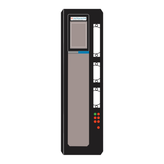
CD1-a Chapter 3 - Inputs-Outputs 1 - CONNECTORS LOCATION 1.1 - AMPLIFIER CONNECTORS CD1-a Command connector Resolver connector 24 Vdc connector Serial link connector Power connector ERROR DISPLAY 2 - X1: RESOLVER CONNECTOR Sub D 9 pins female (male connector is not supplied) -
Page 19: X2: Command Connector, Logic Inputs-Outputs And Encoder
Analog input for external max. current limitation 0 to 10 V for 100 % to 0 % of Imax Reserved input Do not use (to be used by INFRANOR only) 18, 19 AOK: amplifier ready Relay contact: closed if amplifier OK, open if fault. -
Page 20: Specification Of The Analog Inputs: Cv+, Cv-, Ilim
CD1-a 3.1 - SPECIFICATION OF THE ANALOG INPUTS: CV+, CV-, Ilim X2/17 X2/16 10 nF 10 nF X2/15 ILIM X2/3 10 nF X2/25 3.2 - SPECIFICATION OF THE LOGIC OPTOCOUPLED INPUTS: ENABLE, FCP, FCN, RESET, CVO, CI 8.2 KΩ 10 KΩ... -
Page 21: X5 Serial Link
Brake- Brake is not available on amplifier version CD1-a 6 - X9 POWER CONNECTOR: MAINS, MOTOR, BRAKING RESISTOR (CD1-a-230 V AND 400 V) CD1-a-230/I: 10 pins male connector (with 5.08 mm pitch) - Female connector supplied CD1-a-400/I: 10 pins male connector (with 7.62mm pitch) - Female connector supplied Fastening torque of the connector screws: 0.5 Nm... -
Page 22: Chapter 4 - Connections
CD1-a Chapter 4 - Connections 1 - CONNECTION DIAGRAMS 1.1 - CD1-a-230/I AMPLIFIER (For the UL certified connection, see chapter 4, section 3.4). Power relay CD1-a-230/I remote control MAVILOR Motor temp. Power Motor temp. ENABLE AOK/ relay Resolver ENABLE signal... -
Page 23: Cd1-A-400/I Amplifier
Braking resistor Braking ILIMIT Braking resistor resistor CD1-a-400/1.8 to 7.2 : dp 200/100 CD1-a-400/14 : dp 50/200 CD1-a-400/30 and 45: dp 33/280 Circuit breaker curve D I1s = 10 x In ** 10 A for I < or = 14 A 20 A for I = 30 and 45 A The protection, on source side, of both 24 V and power supplies must be made by the user. -
Page 24: Connection Of A Backup Battery For The 24 Vdc Auxiliary Supply
Battery 30A/h The CD1-a amplifier consumption is 320 mA with 24V . So, a 24 V / 30 A/h battery can keep the amplifier under voltage during i.e. a long 3 days week-end or during a mains cut-off without loosing the machine initialization. This backup method is very interesting for saving the machine initialization as well as the axis position even when moving with mains switched off. -
Page 25: Wiring
CD1-a 2 - WIRING (according to EN61000.4-2-3-4-5 and EN55011 standards - see diagram "Shield connection on the connectors " – chapter 4, section 2.2). 2.1 - EARTH WIRING AND EARTHING CAUTION ! Each potential conducting element must be shielded. Several potential conductors in the same sleeve must be twisted and shielded. -
Page 26: Connectors Shield Connection
CD1-a 2.2 - CONNECTORS SHIELD CONNECTION RULE The shield should never be interrupted or corrupted over the whole cable length. Self-sticking copper ribbon if necessary, for increasing the shield diameter in order to get it correctly tightened under the clamp... -
Page 27: Connection Vue Of Cd1-A-400/30 And 45
CD1-a 2.3 - CONNECTION VUE OF CD1-a-400/30 AND 45 Br + Br + Br - Br - 2.4 - MOTOR AND RESOLVER CABLES Motors and resolvers are grounded via their housing. Cable inputs must be made by means of metal connectors with collars allowing the 360° shield connection. -
Page 28: Input Command And Serial Link Cables
CD1-a 2.5 - INPUT COMMAND AND SERIAL LINK CABLES The analog input command signal CV requires a pair twisted and shielded cable. The shield must have a "360°" connection via metallic connectors at both ends. The input command (CV) wiring must be made according to the polarity between the controller and the amplifier (CV+ on "diff high"... -
Page 29: Cd1-A-230/I Drive: Connection Diagram With Protections By "Ul" Fuses
For a multiaxis application with N drives, the fuse rating is calculated by the formula given in the table above. But a rating of 20 A must not be exceeded on 230 V drives (see chapter 4, section 3.5). 3.4 – CD1-a-230/I DRIVE: CONNECTION DIAGRAM WITH PROTECTIONS BY "UL" FUSES (according to the table in section 3.3 of this chapter) -
Page 30: Cd1-A-400/I Drive: Connection Diagram With Protections By "Ul" Fuses
CD1-a 3.5 – CD1-a-400/I DRIVE: CONNECTION DIAGRAM WITH PROTECTIONS BY "UL" FUSES (according to the table in section 3.3 of this chapter) Power relay CD1-a-400/I UL remote control MAVILOR Motor temp. Power Motor temp. ENABLE AOK/ relay Resolver ENABLE signal... -
Page 31: Connection Example For A Ul Compliant Multiaxis Application
3.6 – CONNECTION EXAMPLE FOR A UL COMPLIANT MULTIAXIS APPLICATION 24 V 24 V 24 V 24 V Mains For the choice of the fuses, see chapter 4, section 3.3 CD1-a-230/I : 3 x 230 V CD1-a-400/I : 3 x 400 V Chapter 4 - Connections... -
Page 32: Chapter 5 - Parameter Setting
CD1-a Chapter 5 - Parameter setting The parameter setting softw are VISUAL DRIVE SETUP, which is PC compatible with the WINDOWS® operating system, allows an easy modification of all amplifier parameters. Please, see Web Site www.infranor.fr for downloading the VISUAL DRIVE SETUP software. -
Page 33: Chapter 6 - Commissioning
- dp 50/200 for 14 A current rating. - dp 33/280 for 30 and 45 A current ratings Any braking resistor value lower than 200 Ω for the CD1-a-400/1.8 to 7.2 A amplifier will definitely damage the braking system. The ENABLE signal (X2 connector, pin 20) must be inactive and the CV analog command input (X2 connector, pins 16/17) must be short-circuited. -
Page 34: Switch On The 230 Vac Or 400 Vac Supply (According To The Amplifier Type)
CD1-a 2.3 - Switch on the 230 VAC or 400 VAC supply (according to the amplifier type). Use the power supplies connection drawing while taking into account the AOK relay signal. The red UNDERVOLT. Led must go out after a few seconds. -
Page 35: Speed Loop Adjustment With Vertical Load
CD1-a In case of loud noise in the motor at standstill and when running, check the rigidity of the transmission between motor and load (backlashes and elasticities in gears and couplings). If necessary, start the Auto- tuning procedure while selecting a lower bandwidth. If the problem remains, renew the Auto-tuning while activating the antiresonance filter. -
Page 36: Chapter 7 - Troubleshooting
1.5 - "UNDERVOLT" FAULT (non stored) When switching on the auxiliary 24 V supply, the CD1-a amplifier always displays the UNDERVOLT. fault. The UNDERVOLT. Led will go out when switching on the power voltage, after a few seconds time delay that corresponds to the power capacitors soft start. -
Page 37: Power Stage" Fault
Power supply overvoltage Phase-earth short-circuit Phase-phase short-circuit Power stage short-circuit Power stage overtemperature (on CD1-a-400/I only) PWM control error Power stage supply Braking system error: transistor short-circuit or cycle too high. The VISUAL DRIVE SETUP software allows to identify the “Power stage” fault. -
Page 38: Following Error
CD1-a 1.10 - FOLLOWING ERROR The FOLLOWING ERROR fault corresponds to a following error of the speed loop. Check that the load is actually adjusted to motor and amplifier types. Reduce the accelerations/decelerations. Check that the axis is not positioned on a mechanical stop. -
Page 39: Loud Noise In The Motor At Standstill And When Running
CD1-a 2.7 - LOUD NOISE IN THE MOTOR AT STANDSTILL AND WHEN RUNNING Check the rigidity of the mechanical transmission chain between motor and load (backlash and elasticity in the gearboxes and couplings). Execute the AUTOTUNING command again by choosing a lower bandwidth (Medium or Low). -
Page 40: Chapter 8 - Appendix
CD1-a Chapter 8 - Appendix 1 - HARDWARE ADJUSTMENTS All hardware adjustments of the CD1-a amplifier module are located on the hardware location diagram below. HARDWARE LOCATION DIAGRAM Firmware memory EEPROM parameters LOGIC BOARD R109 Resolver transformation ratio (PRES) Chapter 8 – Appendix... -
Page 41: Adjustment To Various Resolver Types
14,3 K 12,7 K 6,34 K This adjustment is factory set by INFRANOR. Note When using resolvers with a number of pole pairs N > 1, all speed values displayed in the amplifier are equal to N times the motor rotation speed. -
Page 42: Adjustment To Various Motor Types
CD1-a 3 - ADJUSTMENT TO VARIOUS MOTOR TYPES 3.1 - MOTOR THERMAL SENSOR The thermal probe is connected to the X1 resolver connector, pins 1 and 2. 3.1.1 - PTC OR NTC THERMAL PROBE The PTC or NTC configuration is made by means of the VISUAL DRIVE SETUP software. -
Page 43: Use Of The "Limit Switch" Inputs
CD1-a Current limitation in Limiting mode When the amplifier RMS current (I t) reaches the Rated current value, the I t protection limits the amplifier current at this value. The amplifier current limitation diagram is shown below. Amplifier current Maximum current... -
Page 44: Use Of The "Enable" Input
CD1-a 8 - USE OF THE "ENABLE" INPUT The Enable input ensures the amplifier enabling/disabling as shown on the timing diagram below: Enable input pin 20 of X2 +24V Enable/Disable 60 ms Enable Disable 9 - INCREMENTAL ENCODER OUTPUTS Two A and B channels in quadrature with one Z marker pulse per revolution allow to close the position loop via the... -
Page 45: System Of Power Feedback Via A Braking Resistor
It is recommended to mount the braking resistor on the drive with highest current rating. On 400 V drives: CD1-a-400/1.8 to 7.2 A, as from index "P", CD1-a-400/14 A, as from index "H", CD1-a-400/30 and 45 A, as from index "A", an electronic control of the reflected power avoids the overloading of the braking resistor.
Need help?
Do you have a question about the CD1-a and is the answer not in the manual?
Questions and answers