Toshiba nv Series Instruction Manual
Type2 soe function unified controller
Hide thumbs
Also See for nv Series:
- Hardware manual (177 pages) ,
- Instruction manual (148 pages) ,
- User manual (70 pages)
Table of Contents
Advertisement
Quick Links
Advertisement
Table of Contents

Related Manuals for Toshiba nv Series


Summary of Contents for Toshiba nv Series
- Page 1 6F8C1511 Unified Controller nv Series type2 SOE Function Instruction Manual...
- Page 2 (1)The technical information provided herein describes typical operations and applications of the product and does not guarantee the intellectual property rights or other rights of Toshiba or third parties nor allows license of its use. (2)No part or the whole of this document may be reproduced without prior consent.
-
Page 3: Safety Precautions
Specific details Specific details are indicated near the symbol with Warning pictures and text. (Note) Descriptions of Prohibition, Mandatory Action, and Warning vary depending on the display on the main unit. Unified Controller nv series type2 SOE Function Instruction Manual... - Page 4 Safety Precautions on Installation WARNING Ground the device. Otherwise, it may cause an electric shock Ground or fire. CAUTION Do not install, store, or use it in Do not insert any foreign object the following environments. such as wasted lines into the Prohibited Prohibited module or unit.
- Page 5 Mandatory When using the contact relay Turn on the power of the nv series, and then turn on the I/O module supply used for relay output, check the external power and external load Mandatory contact life.
- Page 6 Share the external power supply for the I/O malfunction occurs in the nv series. module with the load power supply whenever possible. If this is not possible,...
- Page 7 Do not insert any metal into the Do not forcefully bend, pull, or gaps of the device main body. twist the power cord and cables. Prohibited Prohibited It may cause fire. It may cause breaks or heating. Unified Controller nv series type2 SOE Function Instruction Manual...
- Page 8 Safety Precautions on Maintenance and Inspection WARNING When installing or removing the When replacing the power fuse module, unit, terminal block, or or alarm fuse of the device, turn Mandatory Mandatory wiring cable, make sure that the off the device. external power supply is off.
- Page 9 For severe stain, use a wet cloth wrung Prohibited module, or board. tightly. It may cause deformation or discoloration Leaving them stained may cause wrong of the device panel, module, or board. decision or malfunction. Unified Controller nv series type2 SOE Function Instruction Manual...
- Page 10 Safety Precautions on Transportation, Storage, and Disposal WARNING Do not throw the lithium battery into a fire. Prohibited The battery may explode. CAUTION When dispose the product, it For transportation and storage treats as industrial waste and of the product, use a conductive Mandatory Mandatory follows the ordinances and...
- Page 11 (except for power supplies below 24V). Remove the sticker from the mount, and attach it on the main body of the nv series, or on a location near the nv series where it can be seen easily.
- Page 12 Toshiba shall not be responsible for any damage caused by an earthquake, lightning and wind, fire for which Toshiba is not responsible for, acts of a third party, other accidents, the user's willful acts or negligence, misuse, or use in abnormal conditions.
- Page 13 Do not use benzene or thinner to remove stain on device or module. It may cause deformation or discoloration of the device panel or module. To keep the system normal and avoid unnecessary troubles, perform daily inspections, regular inspections, and cleaning. Unified Controller nv series type2 SOE Function Instruction Manual...
- Page 14 (5) A place with high humidity 3. When the ambient or internal temperature of the device rises abnormally or failure occurs in the device, stop using the device, turn off the power, and contact one of Toshiba's service representatives. 4. Do not open the case of the device during operation for any purpose other than switch setting.
- Page 15 ("SOE function" hereafter) and the high-speed serial I/O adapter module ("SA9A1 module" hereafter) in the Unified Controller nv series type2. To use the devices correctly and safely, read "Safety Precautions" before use. After reading this manual, keep it in a safe place so that you can read it whenever necessary.
- Page 16 ● Notational conventions The following are the notational conventions for better understanding of this document. Describes what the user should be particularly aware of to handle the product Important correctly. Describes what the user should observe to handle the product correctly. Note Describes a remark.
-
Page 17: Table Of Contents
Start from TOSDIC-CIE DS OIS-DS Program ··········· 47 Show SOE Information ·············································· 48 Switch Node ······························································ 50 Update event run mode ············································· 51 SOE Restart ······························································· 51 Save CSV file ····························································· 52 4.10 Close SOE Information ·············································· 54 Unified Controller nv series type2 SOE Function Instruction Manual... - Page 18 Chapter 5 Troubleshooting …55 Inspection ································································· 60 Chapter 6 6.1.1 Daily inspection ·················································· 60 Maintenance and 6.1.2 Periodical inspection ··········································· 62 Inspection Maintenance Parts ····················································· 63 …59 Life Limited Parts ······················································ 63 Usage Constraints ····················································· 66 Chapter 7 7.1.1 Combination with the other modules and Application engineering tool ·················································...
- Page 19 …69 24VDC System Power Supply Specifications ············· 72 Appendix B Outside Dimensions …73 Appendix C Related Products …75 Appendix D Decimal- Hexadecimal Conversion Table …77 Appendix E Component Module …81 xvii Unified Controller nv series type2 SOE Function Instruction Manual...
- Page 20 xviii 6F8C1511...
- Page 21 Chapter 1 Introducing the SA9A1 Module This chapter describes functions and characteristics of the SA9A1 module, and names and functions of the parts. Functions and Characteristics of the SA9A1 Module ····· 2 Names and Functions of the Parts ································· 5 1.2.1 Names of the parts ··················································...
-
Page 22: Functions And Characteristics Of The Sa9A1 Module
The SA9A1 module collects TC-net I/O event data in the Unified Controller nv series type2. The SA9A1 module connects to the Unified Controller nv Series type2 controller module via high-speed serial TC-net I/O loop transmission, and to the I/O module via high-speed serial TC-net I/O bus transmission. - Page 23 *2 : If one node of SA9A1 module is used, the connection number of other SA9** modules will decrease by one node. *3 : A node is one element which constitutes the network. Unified Controller nv series type2 SOE Function Instruction Manual...
- Page 24 Chapter 1 Introducing the SA9A1 Module Example of system configuration OIS #2 Engineering tool OIS #1 GPS antenna Ethernet Primary Secondary TC-net I/O loop Input data DI module TC-net I/O AI m odule Figure 1-1 Example of SOE function system configuration 6F8C1511...
-
Page 25: Names And Functions Of The Parts
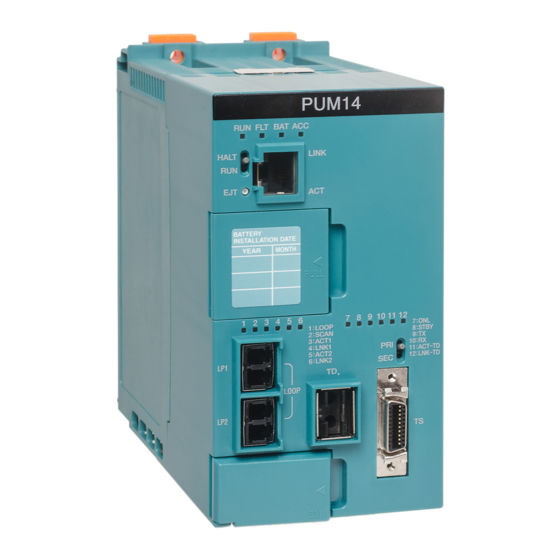
Loop address setting switch ・STN-H ・STN-L Operation mode setting switch ・MODE Serial communication port ・TOOL Maintenance switch ・MAINT TC-net I/O loop connectors ・LP1 ・LP2 Figure 1-2 Names of the parts of the SA9A1 module Unified Controller nv series type2 SOE Function Instruction Manual... -
Page 26: Functions Of The Parts
Chapter 1 Introducing the SA9A1 Module 1.2.2 Functions of the parts State display LED The SA9A1 has state display LEDs in the front that displays the state of the module. Table 1-2 SA9A1 state display LED LED name Description : Module is normal or waiting for parameter download RUN(green) : Module is abnormal : Module is abnormal... - Page 27 Blinking : Transmission/reception is done (normal) Other than above : Transmission/reception is not done (abnormal) Note When the maintenance switch is set to the maintenance state (MAINT), all LEDs go off. Unified Controller nv series type2 SOE Function Instruction Manual...
- Page 28 Chapter 1 Introducing the SA9A1 Module 6F8C1511...
-
Page 29: Installation And Wiring
Chapter 2 Installation and Wiring This chapter describes how to install and wire the TC-net I/O base unit and the SA9A1 module. Types of I/O Base Units ··········································· Installing the Module ··············································· 2.2.1 Vertical Installing of the module ································ 13 2.2.2 Horizontal Installing of the module ····························... - Page 30 Chapter 2 Installation and Wiring Before installing or removing the module, WARNING make sure that the basic unit to which the SA9A1 module is installed is turned off. Mandatory Otherwise, it may cause an electric shock. Do not touch the interior of the product WARNING except the switches.
- Page 31 CAUTION To prevent damage to the screws, use a screwdriver that is suitable for the screws. Prohibited Perform a notification check in the CAUTION application level using the transmission protocol. Mandatory Unified Controller nv series type2 SOE Function Instruction Manual...
-
Page 32: Types Of I/O Base Units
Chapter 2 Installation and Wiring Types of I/O Base Units The SA9A1 module is installed to the base unit (BU901). Connect it to the base unit with other I/O modules installed using a connection cable. For the types and standards of the I/O base unit, refer to "Unified Controller nv series High-speed Serial I/O System TC-net I/O Instruction Manual"... -
Page 33: Installing The Module
CAUTION extreme vibrations, insert a cushion rubber cap (ADP901) or other cushion material Mandatory between the base unit and DIN rail stopper. This will prevent damage and scratch of the case. Unified Controller nv series type2 SOE Function Instruction Manual... - Page 34 Chapter 2 Installation and Wiring Connect the base unit connection cable and cable terminating connector. Connect the cable terminating connector to the base unit at the both ends of the TC-net I/O bus. Normally, the base unit BU901 of the SA9A1 is located at the end of the TC-net I/O bus.
- Page 35 Cross cable CN9R05 (sold separately) Terminating connector TR901 (BU901 accessory) Secure the center part of the cable with Insulok or store the cable in a duct. Figure 2-3 Base unit connection Unified Controller nv series type2 SOE Function Instruction Manual...
- Page 36 Chapter 2 Installation and Wiring Install the SA9A1 module to each of the base units. (1) Hook the module to the slot on the bottom of the module in the lower part of the base unit, and rotate it to fit the connector. (2) Secure it to the base unit with the fixing screw on the top of the module.
-
Page 37: Horizontal Installing Of The Module
I/O module 50mm or more 50mm or more BU901 Power supply External line wiring (Facing the bottom) terminal block (Left side) Figure 2-5 Horizontal installing Unified Controller nv series type2 SOE Function Instruction Manual... -
Page 38: Connecting The Tc-Net I/O Loop Transmission Cable
Chapter 2 Installation and Wiring Connecting the TC-net I/O Loop Transmission Cable Connect the TC-net I/O loop transmission cable. Figure 2-6 shows the order of connection of the cables. Important The connection state between the modules may not be displayed in the V-TOOL if the cables are not connected correctly. -
Page 39: Replacing The Module
Mandatory When the maintenance switch is set to MAINT, the module communication stops and major failure occurs. The controller goes down if no fallback is specified. . Unified Controller nv series type2 SOE Function Instruction Manual... -
Page 40: Removing The Base Unit
Chapter 2 Installation and Wiring Removing the Base Unit When removing the base unit, perform the steps in "2.2 Installing the module" in the reverse order. Also turn off the power. To remove the base unit from the DIN rail, remove all the cables, and slide the stopper (white plastic) on the back of the base unit outward by using a screwdriver. - Page 41 Chapter 3 Setting This chapter describes how to set the switches and parameters to use the module correctly. Switch Setting of the SA9A1 ······································ 22 3.1.1 Loop address setting switch (STN-H, STN-L) ············· 22 3.1.2 Operation mode setting switch (MODE) ···················· 23 Maintenance switch (MAINT) ·································...
-
Page 42: Switch Setting Of The Sa9A1
Chapter 3 Setting Switch Setting of the SA9A1 This section describes how to set the switch in the front of the SA9A1. Important Set the switch that determines the loop address of the SA9A1 module before turning on the power. 3.1.1 Loop address setting switch (STN-H, STN-L) Figure 3-1 shows the configuration of the loop address switch. -
Page 43: Operation Mode Setting Switch (Mode)
Important To avoid wrong operation in a normal state, use a precision screwdriver to operate the maintenance switch that is behind the front panel. Unified Controller nv series type2 SOE Function Instruction Manual... -
Page 44: Setting With The Engineering Tool
/ Integrated Controller V series Engineering Tool 4 Operation Manual -Basic-“ (6F8C1290). Connect the engineering tool and nv series controller via Ethernet. The Ethernet connection in the nv controller can be made using the FN812 module or EN811 module. (Figure 3-4 System configuration of the setting... -
Page 45: Module Parameter Setting
Select I/O node under PU821 in the station tree and select [File]-[New (W)]. Select a I/O node number and select SA9A1 from Node Catcode and click the OK button. Figure 3-5 Module registration screen Figure 3-6 Node Catecode select screen Unified Controller nv series type2 SOE Function Instruction Manual... - Page 46 Chapter 3 Setting Add Unit to the station tree Select unit under SA9A1 in the station tree and select [File]-[New (W)]. Select a unit number and select SOEUnit from Unit Catcode and click the OK button. Figure 3-7 Unit addition screen Figure 3-8 Unit Catecode select screen 6F8C1511...
- Page 47 Select module under SOEUnit in the station tree and select [File]-[New (W)]. Select a slot number and select I/O module from Module Catcode and click the OK button. Figure 3-9 I/O Module addition screen Figure 3-10 Module Catecode select screen Unified Controller nv series type2 SOE Function Instruction Manual...
- Page 48 Chapter 3 Setting Set module parameters Select SA9A1 and select [File]-[ModuleParameter], or right-click SA9A1 and select Module Parameter. Figure 3-11 Module parameter setting screen 6F8C1511...
- Page 49 3.2 Setting with the Engineering Tool The contents of each module parameter are shown as follows. Figure 3-12 Target point setting screen DI bit mask Set up the target point which detects an event Unified Controller nv series type2 SOE Function Instruction Manual...
- Page 50 Chapter 3 Setting Figure 3-13 Stop trigger point setting screen Stop trigger Set up usage of stop trigger point(YES/NO) DI slot No. Set up the slot number of target DI module DI point No. Set up the target DI point number Stop trigger point condition Set up the conditions which a target DI point makes a stop trigger (ON/OFF) 6F8C1511...
- Page 51 Save 2000 event data from the determination time of a condition precedent. When 10 seconds have passed after the condition precedent was satisfied. Last Stop simultaneously with the condition precedent is satisfied. Unified Controller nv series type2 SOE Function Instruction Manual...
- Page 52 Chapter 3 Setting Figure 3-15 AI point setting screen Target point Set up the method of a save as event data at the time of event detection (YES/NO) AI slot No. Set up the slot number of AI module which is the target of event data storage AI point No.
-
Page 53: Soe Guidance Tag Registration
SOE Guidance tag registration is necessary to use OIS Guidance View for SOE condition. Please carry out tag registration in the following procedure. The tag registration uses tag editor of nV-Tool. Select the parameter : [PB:Push Button] Figure 3-16 Tag Editer Parameter Type Unified Controller nv series type2 SOE Function Instruction Manual... - Page 54 Chapter 3 Setting Input a value in the following item to do Tag registration Table 3-3 Tag registration contents Item Set value TYPE PB4 (*1) %MX2.1720.0 *1 : Tag Type can select another PB tag type. (PB2,PB8,etc) Figure 3-17 Tag Editer setting screen 1 6F8C1511...
- Page 55 3.3 Tag Registration Figure 3-18 Tag Editer setting screen 2 Save the parameter after input a set value. Download to Controller Download a parameter to a controller. Unified Controller nv series type2 SOE Function Instruction Manual...
-
Page 56: Time Service Module Ts811
Run mode, Unified Controller nv series type2 becomes Time Data valid status. In the case TS811 GPS valid, Unified Controller nv series type2 can't set the calendar from OIS-DS and nV-Tool. Even if TS811 GPS Fix Status becomes no-fix status, Unified Controller nv series type2 continues valid of Time Data state. -
Page 57: About Leap Second Correction
3.4.2 About leap second correction GPS Time of TS811 is affected by leap second correction. The correction of the leap second of the Unified Controller nv series type2 occurs after controller power supply ON start. And it occurs when conventional world time revises a leap second during Unified Controller nv series type2 operation. - Page 58 Chapter 3 Setting Table 3-4 SOE/TS811 Related System Variables 1720 Information of forming SOE condition <0> Information of forming SOE condition (0: non-formation 1: formation) (for OIS guidance) 1721 SOE operating state state of soe processing active mode <0 , 1> Active mode(SA9A1 event active mode) 0: Initialize 1: download wait 2: active...
-
Page 59: Ois-Ds Engineering Tool
Table 3-5 Event Condition Setting Item Setting Value Exp(UCS1) Event Name SOE_EVENT1 Tag No. The tag number for the notice of SOE SOE_TAG1 registered by nV-Tool Status Figure 3-19 Event Condition Unified Controller nv series type2 SOE Function Instruction Manual... -
Page 60: Program Menu
Chapter 3 Setting 3.5.2 Program Menu In order to start a SOE Information display from Guidance, it is necessary to register a SOE Information display into a “Program Menu”. It is necessary to register the following items by number of UCS. Table 3-6 Program Menu Setting Item Setting Value... -
Page 61: Guidance
Minor ALM Auto Screen No. 10000 + “Program Menu No.” 10001 Event Condition The "Event Name" which registered the tag for the notice of SOE on SOE_EVENT1 "Event Conditions" Figure 3-21 Guidance Unified Controller nv series type2 SOE Function Instruction Manual... - Page 62 Chapter 3 Setting 6F8C1511...
- Page 63 Chapter 4 Startup/Shutdown and Operation This chapter describes startup and the shutdown method of a SOE functional system and the operations of the SOE Information Screen. Checking the Switch before Startup ··························· 42 Startup of the System ················································ 42 Shutdown of the System ············································ 43 Start SOE Information ················································...
-
Page 64: Checking The Switch Before Startup
(or in the order of external power supply → load power supply). Turn on the power in the following order: CAUTION Turn on the power of the nv series, and then turn on the I/O module external power supply and external load Mandatory power. -
Page 65: Shutdown Of The System
Share the external power supply for the I/O module with the load power supply whenever possible. If this is not possible, construct the system so that the external power supply and load power supply are turned off simultaneously. Unified Controller nv series type2 SOE Function Instruction Manual... -
Page 66: Start Soe Information
Chapter 4 Startup/Shutdown and Operation Start SOE Information The method of starting a SOE Information display has the method of starting from guidance, and the method of starting from a TOSDIC-CIE DS OIS program. 4.4.1 Start from Guidance In order to start a SOE Information display from guidance, it is necessary to register “Event Condition”... -
Page 67: Start From Tosdic-Cie Ds Ois-Ds Program
4.4 Start SOE Information 4.4.2 Start from TOSDIC-CIE DS OIS-DS Program Click on the "TOSDIC-CIE DS" - "OIS-DS Program" - "SOE Information" Click Figure 4-2 TOSDIC-CIE DS - OIS-DS Program Unified Controller nv series type2 SOE Function Instruction Manual... -
Page 68: Show Soe Information
Chapter 4 Startup/Shutdown and Operation Show SOE Information The contents displayed on SOE Information are explained. Figure 4-3 SOE Information (1) Node Information Node Type Select Node Type Range: UCS1 to UCS32. Run Mode SA9A1 event run mode is displayed. Contents: Initialize/DL wait/Running/Trigger Stop (2) Event Information Parameter Num... - Page 69 Slot address is displayed. Range: 0 to 15 Point No. Point number is displayed. Range: 0 to 15 Ext Info1 to Ext Info3 Extension Information is displayed. Range: 0 to 4294967295 Unified Controller nv series type2 SOE Function Instruction Manual...
-
Page 70: Switch Node
Chapter 4 Startup/Shutdown and Operation Switch Node How to switch the Node type classification which displays SOE Information is explained. (1) Choose a Node to switch by the Node type of Node Information area, and click on the [switch Node] button. Figure 4-4 Node Information (2) SOE Information is displayed. -
Page 71: Update Event Run Mode
How to switch Run Mode is explained. (1) Click on the [Update] button. Figure 4-6 Update Run Mode button (2) The present Run Mode is displayed. Figure 4-7 Update Run Mode Unified Controller nv series type2 SOE Function Instruction Manual... -
Page 72: Soe Restart
Chapter 4 Startup/Shutdown and Operation SOE Restart How to restart SOE is explained. (1) Click on the [SOE Restart] button. Figure 4-8 SOE Restart botton (2) Since a confirmation message is displayed. Please click on the [Yes] button. Figure 4-9 SOE Restart confirmation message (3) A SOE restart request is notified to SA9A1 module, and SOE resumes. -
Page 73: Save Csv File
How to save CSV file of the contents currently displayed on the SOE Information display is explained. (1) Click on the [Save] button Figure 4-11 Save button (2) [Save As] is displayed. Please specify and save a file name. Figure 4-12 Save as Unified Controller nv series type2 SOE Function Instruction Manual... -
Page 74: Close Soe Information
Chapter 4 Startup/Shutdown and Operation (3) Completion of preservation will display a confirmation message. Please click on the [OK] button. Figure 4-13 Completed 4.10 Close SOE Information How to close a SOE Information display is explained. (1) Click on the [X] button or the [Close] button. Figure 4-14 Close button (2) Close confirmation message is displayed. -
Page 75: Troubleshooting
Chapter 5 Troubleshooting This chapter describes troubleshooting for the TC-net I/O. - Page 76 Abnormal Module error Replace the module. operation Contact one of Toshiba's service representatives. Fault diagnosis of the TC-net I/O loop The SA9A1 has a LED display on the front that displays the state of the TC-net I/O loop. Perform diagnosis by referring to the following table.
- Page 77 Loading the RAS data and system log To load the RAS data and system log, refer to "Unified Controller nv series / Integrated Controller V series Engineering Tool 4 -Basic-” (6F8C1290). When loading fails during serial communication Load them again. Logs related to serial communication may be traced.
- Page 78 Chapter 5 Troubleshooting 6F8C1511...
-
Page 79: Maintenance And
Chapter 6 Maintenance and Inspection This chapter describes details and methods of daily inspection and periodical inspection, and the maintenance parts and the life limited parts. Checking the Switch before Startup ··························· 60 Daily inspection ·················································· 60 6.1.1 6.1.2 Periodical inspection ············································ 62 Maintenance Parts ·····················································... -
Page 80: Inspection
When an error occurs, stop using it CAUTION immediately. When an error occurs such as unable to turn on the Mandatory power, stop using it and contact one of Toshiba's service representatives. Inspection 6.1.1 Daily inspection Check the following items daily while the controller is running. - Page 81 RUN is ON and ALM is OFF during ・Check the registration state and display of the operation. error state of the I/O from the TC-net I/O unit controller for taking measures. Unified Controller nv series type2 SOE Function Instruction Manual...
-
Page 82: Periodical Inspection
WARNING adjust the device, module, or board. It may cause an electric shock, fire, injury, or failure. Prohibited In case of an operation error or failure, contact one of Toshiba's sales representatives. Table 6-2 Periodical inspection items Item Inspection details... -
Page 83: Maintenance Parts
Life Limited Parts To use the product safely for a long time, replace the life limited parts regularly. When replacing them, consult with one of Toshiba's service representatives. The following table shows the life limited parts and their replacement cycles. - Page 84 Chapter 6 Maintenance and Inspection 6F8C1511...
- Page 85 Chapter 7 Application Interface This chapter describes usage constraints of the user application, and the examples of the diagnostic functions. Usage Constraints ····················································· 66 7.1.1 Combination with the other modules and engineering tool ·················································· 66 Implementation Constraints ··································· 66 7.1.2 About TS811 diagnostic ·············································...
-
Page 86: Usage Constraints
Chapter 7 Application Interface Usage Constraints 7.1.1 Combination with the other modules and engineering tool The SA9A1 module is supported in the following PU* modules. Moreover, the engineering tool is supported in the following versions. In the SOE function, the follwing I/O module correspond. PU module Support Remark... -
Page 87: About Ts811 Diagnostic
7.2.1 TS811 diagnostic functions The conditions of TS811 do not influence an operation mode of the Unified controller nv series type2. Therefore, please decide an operation mode of the controller by user program from status of TS811. 7.2.2 Sample program 1 (Duplex switching by GPS Fix Status of TS811) This sample program execute a duplex switching on the following condition. -
Page 88: Sample Program 2
Chapter 7 Application Interface 7.2.3 Sample program 2 (Make a calendar date setable from nV-Tool and OIS-DS) When the online side and standby side GPS Fix status of TS811 is invalid, this program enables set to calendar date on a controller from nV-Tool and OIS-DS. 1. -
Page 89: Specifications
Appendix A Specifications A.1 Common Specifications ·············································· 70 A.2 SA9A1 Specifications ·················································· 71 A.3 BU901 Specifications ··················································· 72 A.4 24VDC System Power Supply Specifications ··············· 72... -
Page 90: Common Specifications
Appendix A Specifications A.1 Common Specifications Table A.1-1 and A.1-2 show the common specifications and long-term storage environment respectively. Table A.1-1 Common specifications Item Specification Operating temperature 0 to 55ºC Storage temperature -40 to 70ºC Humidity 10 to 95%RH (no condensation) Vibration (when not 5 ≤... -
Page 91: Sa9A1 Specifications
Natural air cooling specification Dimensions 35W × 185H × 95Dmm Weight 250g or less Power supply 20.4VDC to 26.4VDC (24VDC + 10% - 15%) Current consumption 24VDC-400mA or less (SA9A1/1 unit) Unified Controller nv series type2 SOE Function Instruction Manual... -
Page 92: Bu901 Specifications
Appendix A Specifications A.3 BU901 Specifications Table A.3-1 shows the specifications of the BU901. Table A.3-1 BU901 specifications Category Item Specification Module Usage For transmission module specification Power terminal 24V, 0V, FG (M3.5 screw each) Insulation resistance 10MΩ or more (50VDC megger) Dimension 72W x 200H x 30D mm (excluding the protrusion) Weight... - Page 93 Appendix B Outside Dimensions...
- Page 94 Appendix B Outside Dimensions The following figure shows the outside dimensions of the SA9A1. Unit:mm Figure B-1 SA9A1 outside dimensions 6F8C1511...
- Page 95 Appendix C Related Products...
- Page 96 Appendix C Related Products Table C-1 Related products Product name Rating Remark 9-pin RS-232C cable Standard length 5m D-sub 6F8C1511...
- Page 97 Appendix D Decimal-hexadecimal Conversion Table...
- Page 98 Appendix D Decimal-hexadecimal Conversion Table Table D-1 Decimal-hexadecimal conversion table (1) Decimal Hexadecimal Decimal Hexadecimal Decimal Hexadecimal Decimal Hexadecimal 6F8C1511...
- Page 99 Table D-1 Decimal-hexadecimal conversion table (2) Decimal Hexadecimal Decimal Hexadecimal Decimal Hexadecimal Decimal Hexadecimal Unified Controller nv series type2 SOE Function Instruction Manual...
- Page 100 Appendix D Decimal-hexadecimal Conversion Table 6F8C1511...
- Page 101 Appendix E Component Module...
- Page 102 Appendix E Component Module Configuration If the time service module TS811 is mounted in UCS, the component module which displays the state of TS811 on the station status display of an OIS window will be added. Current time UCS1 - UCS32 Operation mode CPU I/O Loop Loop connection...
- Page 103 Unified Controller nv Series type2 SOE Function Instruction Manual May, 2013 Second Edition Social Infrastructure Systems Company Automation Products & Facility Solution Division 1-1, Shibaura 1-chome, Minato-ku, Tokyo 105-8001, Japan © Toshiba Corporation 2013 No part of this document may be reproduced All Rights Reserved.
- Page 104 1511.2.1305...
Need help?
Do you have a question about the nv Series and is the answer not in the manual?
Questions and answers