Toshiba nv Series Instruction Manual
Hide thumbs
Also See for nv Series:
- Hardware manual (177 pages) ,
- Instruction manual (148 pages) ,
- User manual (70 pages)
Table of Contents
Advertisement
Quick Links
Advertisement
Table of Contents

Related Manuals for Toshiba nv Series


Summary of Contents for Toshiba nv Series
- Page 1 6F8C1375 Uni ed Controller nv Series FL-net (FL911) Module Instruction Manual...
- Page 2 (1) The technical information provided herein describes typical operations and applications of the product and does not guarantee the intellectual property rights or other rights of Toshiba or third parties nor allows license of its use. (2) No part or the whole of this document may be reproduced without prior consent.
- Page 3 Indicates Warning. Specific details are indicated near the symbol with pictures and text. Warning (Note) Descriptions of Prohibition, Mandatory Action, and Warning vary depending on the display on the main unit. Unified Controller nv series FL-net (FL911) Module Instruction Manual...
- Page 4 Safety Precautions on Installation WARNING Ground the device. Otherwise, it may cause an electric shock Ground or fire. CAUTION Do not install, store, or use it Do not block the ventilation in the following environments. hole or air inlet/outlet. Prohibited Prohibited ・...
- Page 5 Mandatory cloth. For severe stain, use a wet cloth wrung tightly. Leaving them stained may cause wrong decision or malfunction. Unified Controller nv series FL-net (FL911) Module Instruction Manual...
- Page 6 It may cause an electric shock, fire, overheat. injury, or failure. Upon faulty operation or failure, contact Do not touch the terminals of Toshiba's branch office or service the module and unit during offices. No touch energization. Before using, check that the It may cause an electric shock.
- Page 7 When you return the product in its individual package, put the package in a box suitable for transportation of electronic equipment. Unified Controller nv series FL-net (FL911) Module Instruction Manual...
- Page 8 (e.g. employing fool-proof design, fail-safe design, or redundant design). Disclaimer Toshiba shall not be responsible for any damage caused by fire or earthquake, acts of a third party, other accidents, the user's willful acts or negligence, misuse, or use in abnormal conditions.
- Page 9 (6F8C1226) Describes the detailed specifications of the instruction words of the program languages (LD, FBD, and SFC) supported by the nv series and Integrated Controller V series. Unified Controller nv series/Integrated Controller V series Engineering Tool 4 (Basic) Instruction Manual (6F8C1290) Describes how to create, debug, print, and save programs using nV-Tool.
- Page 10 ●Notational conventions The following are the notational conventions for better understanding of this document. Describes what the user should be particularly aware of to handle the product correctly. Important: Describes what the user should observe to handle the product correctly. Note: Describes a remark.
-
Page 11: Table Of Contents
Setting with the Engineering Tool ·····································19 3.3.1 Module parameter setting··············································20 3.3.2 Adding of network ··························································24 3.3.3 Setting network variables ··············································26 3.3.4 Setting FL911 RAS variables·········································29 Chapter 4 Operation ...39 Chapter 5 Troubleshooting ...41 Unified Controller nv series FL-net (FL911) Module Instruction Manual... - Page 12 Inspection ·················································································44 Chapter 6 6.1.1 Daily inspection······························································44 Maintenance and 6.1.2 Periodical inspection······················································45 Inspection Life Limited Parts ···································································45 ...43 Message Transmission ·························································49 Chapter 7 7.1.1 Supported message transmission service types···········49 Application 7.1.2 XMIT_N function block ··················································50 Interface 7.1.3 Message transmission client request ...47 request command/transmission data ····························51 7.1.4...
- Page 13 Main module details·······················································97 E.2.3 Version display·······························································98 E.2.4 Time setting ···································································98 E.2.5 Run mode setting···························································99 E.2.6 LAN management information screen·························100 E.2.7 Scan healthy map ························································101 E.2.8 Memory clear ·······························································102 E.2.9 System log ···································································103 Unified Controller nv series FL-net (FL911) Module Instruction Manual...
- Page 14 Appendix F Ping Response Function …105 6F8C1375...
- Page 15 Chapter 1 Introducing the FL911 Module This chapter describes the functions, characteristics, and names and functions of the FL911 module Functions and Characteristics of the FL911 Module ······ 2 Names and Functions of the Parts ········································ 4 1.2.1 Names of the parts····························································· 4 1.2.2 Functions of the parts·························································...
-
Page 16: Functions And Characteristics Of The Fl911 Module
The FL-net module FL911 is a device to connect the controller main unit of the Unified Controller nv series to FL-net. The Unified Controller nv Series can communicate with other devices on the FL-net system via the FL911. The FL911 complies with the FL-net (OPCN-2) protocol version 2.00. - Page 17 1.1 Functions and Characteristics of the FL911 Module Example of system configuration Unified Controller TC-net I/O loop SA911 SA911 FL911 TC-net FL-net I/O bus FL-net product Figure 1-1 System configuration example Unified Controller nv series FL-net (FL911) Module Instruction Manual...
-
Page 18: Names And Functions Of The Parts
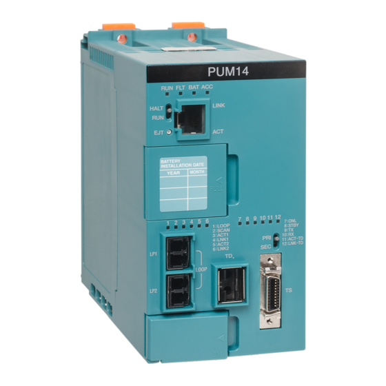
Chapter 1 Introducing the FL911 Module Names and Functions of the Parts 1.2.1 Names of the parts Figure 1-2 shows the names of the parts of the FL911 module. State display LED ・ RUN ・ ERR ・ I/O ・ FLN ・... -
Page 19: Functions Of The Parts
OFF: Transmission is not performed (Note) 1. Check the LED states from the front. (Note) 2. All the LEDs in the above table are OFF when the maintenance switch is turned upward. Unified Controller nv series FL-net (FL911) Module Instruction Manual... - Page 20 Chapter 1 Introducing the FL911 Module Node address setting switch (STN-H, STN-L) Switches to set the station address in hexadecimal. For setting method, refer to "Chapter 3 Setting." Operation mode setting switch (MODE) Switches to set the operation mode. For setting method, refer to "Chapter 3 Setting."...
- Page 21 Chapter 2 Installation and Wiring This chapter describes installation and wiring methods of the FL911 module. Before installation and wiring, read this operation manual thoroughly. Types of I/O Base Units ··························································· 10 Installing the Module ······························································· 11 Replacing the Module ····························································...
- Page 22 Chapter 2 Installation and Wiring Before installing or removing the module, WARNING make sure that the basic unit to which the FL911 module is installed is turned off. Mandatory Otherwise, it may cause an electric shock. Do not touch the interior of the product WARNING except the switches.
- Page 23 CAUTION To prevent damage to the screws, use a screwdriver that Prohibited is suitable for the screws. Perform a notification check in the CAUTION application level using the transmission protocol. Mandatory Unified Controller nv series FL-net (FL911) Module Instruction Manual...
-
Page 24: Types Of I/O Base Units
Chapter 2 Installation and Wiring Types of I/O Base Units The FL911 module is installed to the base unit (BU901). Connect it to the base unit with other I/O modules installed using a connection cable. For the types and standards of the I/O base unit, refer to "Unified Controller nv series High-Speed Serial I/O System TC-net I/O Instruction Manual"... -
Page 25: Installing The Module
DIN rail. DIN rail DIN rail stopper (for upper end) Base unit DIN rail stopper (for lower end) Figure 2-1 Installing the base unit to the DIN rail Unified Controller nv series FL-net (FL911) Module Instruction Manual... - Page 26 Chapter 2 Installation and Wiring When using it in an environment with CAUTION extreme vibrations, insert a cushion rubber Mandatory cap (ADP901) or other cushion material between the base unit and DIN rail stopper. This will prevent damage and scratch of the case. Connect the base unit connection cable and cable terminating connector.
- Page 27 Figure 2-3 Installing the module Perform a check before operation. Before turning on the power to operate the product, check again that the switch setting, installation, and wiring are as described in this operation manual. Unified Controller nv series FL-net (FL911) Module Instruction Manual...
-
Page 28: Replacing The Module
Chapter 2 Installation and Wiring Replacing the Module The FL911 module can be replaced while the system is energized or not energized. When replacing them while the system is energized, set the maintenance switch to the up (MAINT) position for the FL911 module. For the FL911, remove the FL-net transmission cable (Ethernet cable :... - Page 29 Chapter 3 Setting Switch Setting ········································································· 16 3.1.1 TC-net I/O bus address switch (I/O) ································ 16 3.1.2 Node address setting switch (STN-H, STN-L)················· 16 3.1.3 Operation mode setting switch (MODE) ·························· 17 3.1.4 Maintenance switch (MAINT) ······································· 17 Module Parameter Setting ······················································...
-
Page 30: Switch Setting
Chapter 3 Setting Switch Setting The switches that determine the operation mode and node address are on the front panel of the FL911 module. The method to set the switches is shown below. Important Set the switches that determine the operation mode and station address of the FL911 module before turning the power on. -
Page 31: Operation Mode Setting Switch (Mode)
・ For setting, use a small slotted screwdriver. Turn the switch upward (MAINT) when inserting or removing the module to separate from the system. After completing the installation, turn the switch downward (RUN) before returning to normal operation. Unified Controller nv series FL-net (FL911) Module Instruction Manual... -
Page 32: Network Parameter Setting
Chapter 3 Setting Network Parameter Setting The network parameters can be set with the operation mode setting switches and node address setting switches. For methods to set these switches, refer to "Table 3-1 Station address setting" and "Table 3-2 Operation mode setting table." For the FL911 module, the following network parameters must be set. -
Page 33: Setting With The Engineering Tool
Controller V series Engineering Tool 4(Basic) Instruction Manual"(6F8C1290). Connect the engineering tool and nv series controller via Ethernet. The Ethernet connection in the nv controller can be made using the FL911 module. (Figure 3-1 System configuration of the setting example). -
Page 34: Module Parameter Setting
Chapter 3 Setting 3.3.1 Module parameter setting Set the parameters of the FL911 in the following steps. Register the FL911 module from the product tree. Select [Station] under the created system, and select [New]. Figure 3-2 Module registration screen 6F8C1375... - Page 35 When you select the added module and select [Module Parameters] from the File menu, the parameter screen is displayed. Alternately, select the FL911, and right-click it, and select Module Parameters. Figure 3-3 Module parameter select screen Unified Controller nv series FL-net (FL911) Module Instruction Manual...
- Page 36 Chapter 3 Setting Set module parameters. In the module parameter setting screen of the FL911, set the module parameters for the FL911. Figure 3-4 Module parameter setting screen The details of the module parameters are shown below. I/O loop scan speed The scan speed for data about the FL911 module in the I/O loop is specified.
- Page 37 Restart the system. The downloaded information becomes effective from the next startup. After the download is complete, turn ON the power of the FL911, which is supplied to SA9**, from OFF. Unified Controller nv series FL-net (FL911) Module Instruction Manual...
-
Page 38: Adding Of Network
Chapter 3 Setting Note Be careful so that the address does not overlap with other nodes. 3.3.2 Adding of network Add a network from the product tree. Select Network under Systems, and select [New]. Figure 3-5 Network name setting screen Select FL-net LAN in Network Model Name. - Page 39 Register the FL911 to the created FL-netLAN. The FL911 module previously added is displayed in the module addition dialog. Select it to connect to the FL-netLAN. Figure 3-7 Network registration screen Unified Controller nv series FL-net (FL911) Module Instruction Manual...
-
Page 40: Setting Network Variables
Chapter 3 Setting 3.3.3 Setting network variables Assign the common memory of the FL-net to the system network variables. This operation allows the user programs on the controller to use the cyclic data of the common memory Area 1 and Area 2 communicated via cyclic transmission of the FL-net as network variables. - Page 41 In the lower half of the network edit screen, register the network variables as input data. From the [Reception Node] and [Input Controller] pull-down menus, select the controller inputting the network variables. Unified Controller nv series FL-net (FL911) Module Instruction Manual...
- Page 42 Chapter 3 Setting In the upper half of the network edit screen, select the network variables to output, and click the [Assign to Inputs] button. They are registered in the lower half of the screen. Figure 3-10 Network edit (input variable selection) screen 6F8C1375...
-
Page 43: Setting Fl911 Ras Variables
Select the target FL911, and right-click it to select [I/O Variables]. Figure 3-11 I/O variables select screen The RAS variables such as FL-net RAS information, own node management information, MIB information, and FA debug counter can be selected using tabs. Unified Controller nv series FL-net (FL911) Module Instruction Manual... - Page 44 Chapter 3 Setting FL-net RAS information The FL-net RAS information includes healthy information, message reception information, online map, and cyclic data validity map. The details and structure of the information are shown below. Figure 3-12 FL-net RAS information screen ...
- Page 45 239 238 237 236 235 234 233 232 231 230 229 228 227 226 225 224 254 253 252 251 250 249 248 247 246 245 244 243 242 241 240 Figure 3-15 Online map (FL_ONL) Unified Controller nv series FL-net (FL911) Module Instruction Manual...
- Page 46 Chapter 3 Setting Cyclic data validity map (FL_CYC) It displays the effective node numbers of the FL-net cyclic data in a bit map (the same as in "2.1.3 Online map"). Remark The own node is not displayed. Bit='1':Enabled, Bit='0':Disabled offset b15 b14 b13 b12 b11 b10 111 110 109 108 107 106 105 104 103 102 101 100...
- Page 47 Area 2 on the FL-net. Therefore, it is different from the address of Area 2 registered in the Engineering Tool. Example: If "512" is registered in the Engineering Tool, the display above will be "0." Unified Controller nv series FL-net (FL911) Module Instruction Manual...
- Page 48 Chapter 3 Setting Network management table information (FL_NET) It displays the network management table information of the FL-net. offset Reserved Token retention node number Reserved Minimum allowable frame interval Refresh cycle allowed time setting value Refresh cycle measured value (current value) Refresh cycle measured value (maximum value) Refresh cycle measured value (minimum value) Reserved...
- Page 49 3.3 Setting with the Engineering Tool MIB information The details and structure of the MIB information are shown below. Figure 3-21 MIB information screen Unified Controller nv series FL-net (FL911) Module Instruction Manual...
- Page 50 Chapter 3 Setting MIB information (FL_MIB) It displays the MIB information. offset Total number of reception octets Number of reception packets other than broadcast/multicast Number of reception packets of broadcast/multicast Number of reception packets discarded due to resource restrictions Number of reception packets discarded due to a format error Number of reception packets sent to an undefined protocol Total number of transmission octets...
- Page 51 RCT timeout count Cyclic data discarding count Event State Cyclic CBN error occurrence count Cyclic TBN error occurrence count Cyclic BSIZE error occurrence count Figure 3-24 FA debug counter information (FL_FA) (Part 1) Unified Controller nv series FL-net (FL911) Module Instruction Manual...
- Page 52 Chapter 3 Setting Message V-SEQ error occurrence count Message SEQ error occurrence count Message retransmission over count ACK error ACK normal Buffer full error Queuing initialization not complete Sequence number error (message reception side) Sequence number version error (message reception side) Size error (message reception side) Reserved Reserved...
- Page 53 Chapter 4 Operation This chapter describes the operations of the FL911 module, such as checking before operation, startup, and shutdown.
- Page 54 5. If the module doesn't start up or if the operation is erroneous, stop using the product immediately and contact one of Toshiba's service representatives. Shutdown operation To shut down, turn off the power of the power supply module.
- Page 55 Chapter 5 Troubleshooting This chapter describes troubleshooting for the FL911 module.
- Page 56 Loading the RAS data and system log To load the RAS data and system log, refer to "Unified Controller nv series / Integrated Controller V series Engineering Tool 4 (Basic) Instruction Manual (6E8C4890)." When loading fails during serial communication Load them again.
- Page 57 Chapter 6 Maintenance and Inspection This chapter describes maintenance and inspection such as daily inspection, periodical inspection, and cleaning of FL911 module. Inspection ··················································································· 44 6.1.1 Daily inspection ······························································ 44 6.1.2 Periodical inspection ······················································ 45 Life Limited Parts ······································································ 45...
-
Page 58: Inspection
The cable is connected correctly. Cable connection is normal. The modular connector is locked. Cable connection is not loose or has an abnormal appearance. If any abnormality is found, contact one of Toshiba's service representatives. 6F8C1375... -
Page 59: Periodical Inspection
To prevent accidents and use the product safely for long-term operation, it is recommended performing a periodical inspection every 6 months. Also, it is recommended replacing life limited parts regularly (refer to "6.2 Life limited parts"). For a periodical inspection, consult with one of Toshiba's service representatives. Life Limited Parts To use the product safely for a long time, replace the life limited parts regularly. - Page 60 Chapter 6 Maintenance and Inspection 6F8C1375...
- Page 61 Chapter 7 Application Interface This chapter describes message transmission, various types of information that can be viewed with the MRE-AD_N instruction, and usage constraints of the application interface. Message Transmission ··························································· 49 7.1.1 Supported message transmission service types ············· 49 7.1.2 XMIT_N function block·····················································...
- Page 62 Chapter 7 Application Interface 7.2.15 Management information area········································· 72 Usage Constraints ···································································· 75 Assignment of FL911 Management Blocks ······················· 76 6F8C1375...
-
Page 63: Message Transmission
Table 7-2 List of supported message transmission services (one to N) Message transmission type Client function Server function Log data clear ○ ○ Vendor-specific message × × Permeation message × × ○: Supported/×:Not supported Unified Controller nv series FL-net (FL911) Module Instruction Manual... -
Page 64: Xmit_N Function Block
Chapter 7 Application Interface 7.1.2 XMIT_N function block This section describes the XMIT_N function block that is used to issue a message transmission request from the Unified Controller to the FL911. <Symbols> XMIT_N BOOL DONE BOOL ERROR BOOL STATUS DATA : Execution request (BOOL) (Note: The instruction is executed at the rising edge of the REQ signal.) : FL911 installation location/target node number of message... -
Page 65: Message Transmission Client Request
"-5106(M_RLT= abnormal reception" is stored in the STATUS area of the XMIT_N function block. The error code of the server side node is not stored. Figure 7-3 Byte block write request Unified Controller nv series FL-net (FL911) Module Instruction Manual... - Page 66 Chapter 7 Application Interface Word block read DATA 65005 Data read from the specified virtual address Virtual address (L) Virtual address (H) Read word size (Note) 1. The completion status information after the execution of this request is stored in the STATUS area of the XMIT_N function block.
- Page 67 2. If an abnormal response (M_RLT=1) is returned from the server side node, "-5106(M_RLT= abnormal reception" is stored in the STATUS area of the XMIT_N function block. The error code of the server side node is not stored. Figure 7-9 Operation instruction request Unified Controller nv series FL-net (FL911) Module Instruction Manual...
- Page 68 Chapter 7 Application Interface Profile read DATA 65011 +0 Read data length Data area length +1 Read profile information (Note) 1. The completion status information after the execution of this request is stored in the STATUS area of the XMIT_N function block. For the details of the completion status information, refer to "7.1.5 Completion status."...
- Page 69 2. If an abnormal response (M_RLT=1) is returned from the server side node, "-5106(M_RLT= abnormal reception" is stored in the STATUS area of the XMIT_N function block. The error code of the server side node is not stored. Figure 7-13 Message loopback request Unified Controller nv series FL-net (FL911) Module Instruction Manual...
-
Page 70: Communication Data Of Message Transmission
Chapter 7 Application Interface 7.1.4 Communication data of message transmission Byte block read Table 7-3 Byte block read Item Data part detail Request None Normal response Read data (M_RLT=0) The size can be any size up to 1024 octets. Abnormal response None (M_RLT=1) - Page 71 +24 Refresh cycle allowed time setting value +25 Refresh cycle measured value (current value) +26 Refresh cycle measured value (maximum value) +27 Refresh cycle measured value (minimum value) Abnormal response None (M_RLT=1) Unimplemented None response (M_RLT=2) Unified Controller nv series FL-net (FL911) Module Instruction Manual...
- Page 72 Chapter 7 Application Interface Note "Common memory Area 2 start address" is displayed as the offset address from the beginning of Area 2 on the FL-net. Therefore, it is different from the address of Area 2 registered in the Engineering Tool. (Example) If "512"...
- Page 73 Item Data part detail Request None Normal response Permeation message service data (M_RLT=0) The size can be any size up to 1024 octets. Abnormal response None (M_RLT=1) Unimplemented response None (M_RLT=2) Unified Controller nv series FL-net (FL911) Module Instruction Manual...
- Page 74 Chapter 7 Application Interface Log data read Table 7-13 Log data read Item Data part detail Request None Normal response Read data (M_RLT=0) For the data, refer to JEM1479 Attachment 2. The size is 512 octets. Abnormal response None (M_RLT=1) Unimplemented response None...
-
Page 75: Completion Status
-161 An address other than Class C was specified for the IP address of the FL911 for a parameter setting request. LP→ OS information error -5100 Parameter error of XMIT_N FB (data length specification value) Unified Controller nv series FL-net (FL911) Module Instruction Manual... - Page 76 Chapter 7 Application Interface Table 7-16 Completion status list (Part 2) Completion name Code Description Port being used by user -5101 Other XMIT_N FB is executing message transmission and FL911 dedicated request. Port being used by OS -5102 The controller OS is executing message transmission and FL911 dedicated request.
-
Page 77: Mread_N, Mwrite_N
Device profile [Refer to 7.2.13 Device profile] (112 bytes) 0x120 Log information area [Refer to 7.2.14 Log information area] (224 bytes) 0x2000 Management information area [Refer to 7.2.15 Management information area] (6656 bytes) 0x1BFE Unified Controller nv series FL-net (FL911) Module Instruction Manual... -
Page 78: Sw Healthy Information
Chapter 7 Application Interface 7.2.1 SW healthy information Displays that the software is running. It is counter (48-bit) information updated in intervals of 1ms. 0x000 0x002 0x004 7.2.2 HW version information Displays the HW version information (Fenix3). offset b15 0x00A Version Revision 7.2.3... -
Page 79: Online Map
0x05C 239 238 237 236 235 234 233 232 231 230 229 228 227 226 225 224 0x05E 254 253 252 251 250 249 248 247 246 245 244 243 242 241 240 (Bit='1': Subscribing, Bit='0': Not subscribing) Figure 7-14 Online map Unified Controller nv series FL-net (FL911) Module Instruction Manual... -
Page 80: Cyclic Data Validity Map
Chapter 7 Application Interface 7.2.6 Cyclic data validity map Displays the effective node numbers of the FL-net cyclic data in a bit map. It does not display the own node. b15 b14 b13 b12 b11 b10 0x060 15 0x062 31 0x064 47 0x066 63 0x068 79... -
Page 81: Station Status
0 : No overlapping node number exists 1 : In test operation Used in a certification test. Always '0' in normal operation. 0 : In normal operation Unified Controller nv series FL-net (FL911) Module Instruction Manual... -
Page 82: Down Information
Chapter 7 Application Interface 7.2.8 Down information The down information contains the reason why the FL-net module entered the ERR mode. 0x082 Down information Table 7-18 Down information Down information Description 0x0010 External WDT error NMI occurred due to external WDT. 0x0020 Bus stall NMI occurred due to bus stall. -
Page 83: Node Number
The MAC address (Example: AA-BB-CC-DD-EE-FF) of the FL-net module is set (valid in other than the INZ mode). 0x096 0x098 0x09A 7.2.13 Device profile The device profile of the FL911 is set (112 bytes). Unified Controller nv series FL-net (FL911) Module Instruction Manual... -
Page 84: Log Information Area
Chapter 7 Application Interface 7.2.14 Log information area 0x120 Totalizing socket part transmission count Transmission 0x122 Reserved 0x124 Totalizing socket part transmission error count 0x126 Reserved 0x128 Ethernet transmission error count (not implemented) 0x12A Reserved 0x12C Totalizing socket part reception count 0x12E Reserved 0x130... - Page 85 Frame wait state count 0x1AE Reserved 0x1B0 Subscription count 0x1B2 Reserved 0x1B4 Self separation count 0x1B6 Reserved 0x1B8 Skip separation count 0x1BA Reserved 0x1BC Other node separation recognition count 0x1BE Reserved Unified Controller nv series FL-net (FL911) Module Instruction Manual...
-
Page 86: Management Information Area
Chapter 7 Application Interface 7.2.15 Management information area 0x200 Own node management table [Refer to 7.2.15 (1)] 0x240 Network management table [Refer to 7.2.15 (2)] 0x250 RAS counter [7.2.15 (3) RAS counter] (32 bytes) 0x400 Not used 0x408 Subscription node management table (Subscription #CTBL) Node #1 [Refer to 7.2.15 (4)] 0x410 Subscription node management table (Subscription #CTBL) - Page 87 Reserved Token retention node number 0x242 Reserved Minimum allowable frame interval 0x244 RCT current value 0x246 RCT measured value 0x248 Maximum RCT measured value 0x24A Minimum RCT measured value 0x24C Reserved Unified Controller nv series FL-net (FL911) Module Instruction Manual...
- Page 88 Chapter 7 Application Interface (3) RAS counter 0x250 Normal reception count 0x252 Not used Long packet reception count 0x254 Short packet reception count 0x256 0x258 Alignment error count CRC error count 0x25A Overflow count 0x25C 0x25E Reception buffer error count Normal transmission count 0x260 Transmission request count...
-
Page 89: Usage Constraints
Area 2 can be assigned from the beginning to 1.5K word. (Do not assign the last 6.5K word of Area 2 as transmission area. All 0.5K word can be assigned for Area 1). Unified Controller nv series FL-net (FL911) Module Instruction Manual... -
Page 90: Assignment Of Fl911 Management Blocks
Chapter 7 Application Interface Assignment of FL911 Management Blocks The management blocks of the FL911 are assigned to the following blocks on the TC-net I/O loop. 96+(TC-net I/O loop address of the SA911/SA912 to which the FL911 is installed -3)×16+TC-net I/O bus address at which the FL911 is installed (Example) TC-net I/O loop address of the SA911/SA912 to which the FL911 is installed: 5 TC-net I/O bus address at which the FL911 is installed: 2... - Page 91 Version Revision Reception message flag Notifies that a FL-net message is received. '0x00000000' is set if no message exists, or '0x00000001' is set if any message exists. offset b15 Unified Controller nv series FL-net (FL911) Module Instruction Manual...
- Page 92 Chapter 7 Application Interface Online map Displays the node numbers subscribing to the FL-net network in a bit map. It also displays the own node. (Bit='1': Subscribed, Bit='0': Not subscribed) offset b15 b14 b13 b12 b11 b10 111 110 109 108 107 106 105 104 103 102 101 100 127 126 125 124 123 122 121 120 119 118 117 116 115 114 113 112...
- Page 93 Appendix A Specifications A.1 General Specifications ···························································· 80 A.2 FL911 Transmission Specifications ···································· 81 A.3 Function Specifications ·························································· 82 A.4 Serial Communication Port (RS-232C) Transmission Specifications ················································· 82...
-
Page 94: General Specifications
Appendix A Specifications A.1 General Specifications Table A-1 FL911 general specifications Item Specification Operating temperature range 0 to 55 C (product ambient temperature) Operating humidity range 10 to 95%RH (no condensation) -40 to 70 C Storage temperature range Storage humidity range 5 to 95%RH (no condensation) Power voltage range... -
Page 95: Fl911 Transmission Specifications
Transmission path Single bus Transmission cable/cable Category 5 length Twisted pair cable: Max.100m Node count Up to 254 nodes/system Maximum number of FL911 Up to 16 modules/controller modules installed Interface RJ-45 connector Unified Controller nv series FL-net (FL911) Module Instruction Manual... -
Page 96: Function Specifications
Appendix A Specifications A.3 Function Specifications Table A-3 Function specifications Item Specification Protocol UDP/IP、FA link protocol Cyclic transmission Transmission method (Note) Perform a transmission check of transmission data in the application level. A.4 Serial Communication Port (RS-232C) Transmission Specifications Table A-4 Serial specifications Item Specification... - Page 97 Appendix B Outside Dimensions...
- Page 98 Appendix B Outside Dimensions The following figure shows the outside dimensions of the FL911. 94.5 Figure B-1 FL911 outside dimensions 6F8C1375...
- Page 99 Appendix C Related Products...
- Page 100 Appendix C Related Products Table C-1 Related products Product name Rating Remark 9-pin RS-232C cable Standard length 5m D-sub 6F8C1375...
- Page 101 Appendix D Decimal-hexadecimal Conversion Table...
- Page 102 Appendix D Decimal-hexadecimal Conversion Table Table D-1 Decimal-hexadecimal conversion table (1) Decimal Hexadecimal Decimal Hexadecimal Decimal Hexadecimal Decimal Hexadecimal 6F8C1375...
- Page 103 Table D-1 Decimal-hexadecimal conversion table (2) Decimal Hexadecimal Decimal Hexadecimal Decimal Hexadecimal Decimal Hexadecimal Unified Controller nv series FL-net (FL911) Module Instruction Manual...
- Page 104 Appendix D Decimal-hexadecimal Conversion Table 6F8C1375...
- Page 105 Appendix E FL654 System View Screen Instruction Manual When using the PU811/PU866 controller, the FL654 system view screen with the engineering tool is available. Introduction ··································································· 92 Attention ········································································ 92 FL654 Module Parameters ········································ 93 E.1.1 FL654 connect route ········································ 94 E.1.2 Parameters ··························································...
-
Page 106: Introduction
Remark ・ The above function is supported from FL911 firmware version V01.10. Reference documents Unified Controller nv series/Integrated Controller V series Engineering Tool 4 (Basic) Instruction Manual (6F8C1290) model2000 FL-net(OPCN-2) Remote I/O Station Module(FL654)User’s Manual... -
Page 107: Fl654 Module Parameters
E.1 FL654 Module Parameters To display the FL654 module parameter screen, select FL654 from the module tree, right-click it and select [Module Parameters] from the menu displayed. The Module parameter screen is displayed. Unified Controller nv series FL-net (FL911) Module Instruction Manual... -
Page 108: Fl654 Connect Route
Appendix E FL654 System View Screen Instruction Manual E.1.1 FL654 connect route setting To operate the FL654 module from the tool, you need to set the path information as to which nv station and FL911 module you use to transmit data. The settings can be made on the [nv Connect route] tab on the FL654 Module parameters screen. -
Page 109: Parameters
E.1 FL654 Module Parameters E.1.2 Parameters To read/write the module parameters, select the [Parameter] tab on the Module parameters screen. E.1.3 Data To display data, select the [Data] tab on the Module parameters screen. Unified Controller nv series FL-net (FL911) Module Instruction Manual... -
Page 110: System View
Appendix E FL654 System View Screen Instruction Manual E.2 System View Select the FL654 station you wish to display from the station tree, and right-click it to select [System View] from the menu displayed. The Station Status display screen is displayed. 6F8C1375... -
Page 111: Station Status Display
Select FL654 from [Station Status] on the system view, and select [Main Module Detail Alarm] from the [Tool] menu. (You can also activate it by clicking the [Open Detail] button.) Detailed information on the main module alarm status is displayed. Unified Controller nv series FL-net (FL911) Module Instruction Manual... -
Page 112: Version Display
Appendix E FL654 System View Screen Instruction Manual E.2.3 Version display Select FL654 from [Station Status] on the system view, and select [Version] from the [Tool] menu. The version information of the FL654 module is displayed. E.2.4 Time setting Select FL654 from [Station Status] on the system view, and select [Set Time] from the [Tool] menu. -
Page 113: Run Mode Setting
The request for changing the operation status to the specified status is executed. After the request is executed, make sure that the operation status is changed over to the desired status. Unified Controller nv series FL-net (FL911) Module Instruction Manual... -
Page 114: Lan Management Information Screen
Appendix E FL654 System View Screen Instruction Manual E.2.6 LAN management information screen Select FL654 from [Station Status] on the system view, select [LAN Management Information] from the [Tool] menu. The LAN Management Information is displayed. 6F8C1375... -
Page 115: Scan Healthy Map
Click the [Scan healthy map] button on the LAN management information screen. The Scan healthy map screen is displayed. The node number is displayed in each block. Green characters mean healthy, while red means unhealthy. Unified Controller nv series FL-net (FL911) Module Instruction Manual... -
Page 116: Memory Clear
Appendix E FL654 System View Screen Instruction Manual E.2.8 Memory clear Select FL654 from [Station Status] on the system view, and select [Maintenance] from the [Tool] menu. (You can also activate it by clicking the [Maintenance] button.) The Maintenance Panel screen is displayed. Select the [Memory operation] tab, and select [Clear memory] from the [Operation] pull-down menu. -
Page 117: System Log
On the [System Log] screen, system log information of the specified controller is displayed by date. All information on the error, event, transmission and intervention logs are displayed by default. You can also select part of the information to be displayed. Unified Controller nv series FL-net (FL911) Module Instruction Manual... - Page 118 Appendix E FL654 System View Screen Instruction Manual If you wish to see further information on the logs, you can check the details on the [Log Details] screen. To display [Log Details], double-click on the target log, or select [Details] from the [Display] menu while the target log is being selected. Causes and countermeasures are also displayed on the log details display screen.
- Page 119 Appendix F Ping Response Function...
- Page 120 Appendix F Ping Response Function The FL911 module can respond to ping. This function can be used to check the connection of transmission paths during system configuration. *Ping cannot be sent from the FL911 module. *Please note that the FL-net transmission may be affected if ping is sent during the FL-net data transmission when the system is active.
- Page 121 Uni ed Controller nv Series FL-net (FL911) Module Instruction Manual June 30, 2011 Seventh Edition Social Infrastructure Systems Company Automation Products & Facility Solution Division 1-1, Shibaura 1-chome, Minato-ku, Tokyo 105-8001, Japan © Toshiba Corporation 2008-2011 No part of this document may be reproduced All Right Reserved.
- Page 122 1-1, Shibaura 1-chome, Minato-ku, Tokyo 105-8001, Japan 1375.7.1106...
Need help?
Do you have a question about the nv Series and is the answer not in the manual?
Questions and answers