Toshiba nv Series Instruction Manual
Hide thumbs
Also See for nv Series:
- Hardware manual (177 pages) ,
- Instruction manual (148 pages) ,
- User manual (70 pages)
Table of Contents
Advertisement
Quick Links
Advertisement
Table of Contents

Related Manuals for Toshiba nv Series


Summary of Contents for Toshiba nv Series
- Page 1 6F8C1865 Unified Controller nv series Secure System Instruction Manual...
- Page 2 Microsoft, Windows is registered trademark of U.S. Microsoft Corporation in the U.S. and other countries. Linux is registered trademark or trademark of Mr. Linus Torvalds in the U.S., Japan and other countries. © Toshiba Infrastructure Systems & Solutions Corporation. 2018-2019 All Rights Reserved.
- Page 3 Mandatory Indicates Warning. Specific details are indicated near the symbol with pictures and text. Warning (Note) Descriptions of Prohibition, Mandatory Action, and Warning vary depending on the display on the main unit. Unified Controller nv series Secure System Instruction Manual...
- Page 4 Safety Precautions in Installation WARNING Ground the device. DO NOT disassemble or adjust the optical module. Otherwise, it may cause an electric shock Ground Prohibited or fire. The device using laser beam is class 1 device and won’t radiate harmful light but may cause eye injury if it is disassembled or adjusted by an unqualified person.
- Page 5 Construct the emergency stop circuit shock or mechanical failure. and interlock circuit outside the nv series. Mandatory Otherwise, failure or malfunction of nv series may cause injury or damage to the equipment. Unified Controller nv series Secure System Instruction Manual...
- Page 6 When the ambient or internal Upon faulty operation or failure, contact temperature of the device rises Toshiba's branch office or service offices. abnormally or failure occurs in the Prohibited device, stop using the device. Using it as it is may cause fire due to overheat.
- Page 7 Mandatory Mandatory Turn on the power of the nv series, If this order is not followed, it may cause and then turn on the I/O module an accident or damage to the machine.
- Page 8 Safety Precautions in Maintenance and Inspection WARNING When installing or removing the When replacing the power fuse or module, unit, terminal block, or wiring alarm fuse of the device, turn off the cable, make sure that the external device. Mandatory Mandatory power supply is off.
- Page 9 Dispose the unit and module of the the ordinances or rules of the local nv series as industrial waste. government. Mandatory Mandatory Otherwise, it may cause environmental Otherwise, it may cause environmental damage. damage. Unified Controller nv series Secure System Instruction Manual...
- Page 10 6. Checking the Warning Label on the Main Body Check that warning label is attached on the main body. If the label is missing or hard to read due to stain, contact one of Toshiba sales representatives. [Warning symbols on the nv series main body] This symbol is a warning symbol for dangerous parts.
- Page 11 ■ Toshiba shall not be responsible for any damage caused by an earthquake, lightning and wind, fire for which Toshiba is not responsible for, acts of a third party, other accidents, the user's willful acts or negligence, misuse, or use in abnormal conditions.
- Page 12 Precautions in Use ● About system protection If there is a power outage during operation or if the power supply system including the AC power switch is turned off, the system malfunctions and the program and data may be lost. We recommend installing an uninterruptible power supply and utilizing the shutdown function to prevent these damages.
- Page 13 Manuals of nv series In addition to this manual, there are the following as manuals of the nv series. ・ Unified Controller nv series / Integrated Controller V series Programming Instructions (LD/FBD/SFC/ST) (6F8C1226) It describes the specification details of each command about program languages (LD, FBD, SFC and ST) supported by nv series, nv series and V series.
- Page 14 Introduction This manual describes Unified Controller nv series Secure System. To use the device correctly, read this manual thoroughly before use. Keep this manual in a safe place so that you can read it whenever necessary. For installation, setting, operation and maintenance of the security compliant module(PU821S / FN812S), refer to each instruction manual.
-
Page 15: Table Of Contents
Security Authentication screen ················································· 52 Function Authentication history ················································· 65 …39 PU821S ···································································· 72 Appendix A FN812S ···································································· 73 Hardware specification …71 I/O modules ······························································· 76 Appendix B Supported modules …75 xiii Unified Controller nv series Secure System Instruction Manual... - Page 16 Backup of System Information ····································· 80 Appendix C Restore of System Information ···································· 81 Maintenance of System Information …79 6F8C1865...
- Page 17 Chapter 1 Secure System The secure system is one which adopted the Unified Controller nv series type2 conforming to EDSA certification level 1. Outline ·································································· 2 System Configuration ················································ 3 Constraints and operational conditions ·························· 5 Secure package configuration ····································· 8 Recommended configuration ······································...
-
Page 18: Outline
Chapter 1 Secure System Outline The secure system is one which adopted the Unified Controller nv series type2 conforming to EDSA certification level 1. This manual is for an administrator of the secure system. The administrator is responsible for overseeing the secure system to be designed, operated, and maintained under the constraints and operating conditions described in this manual. -
Page 19: System Configuration
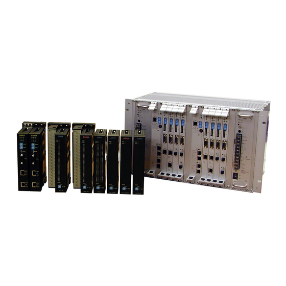
Component Outline PU821S module It is a secure CPU module of Unified controller nv series type2. (abbr. PU or PU821S) FN812S module It is a secure Ethernet module of Unified controller nv series (abbr. - Page 20 Chapter 1 Secure System The following figure shows a system configuration. Figure1.1. Outline 6F8C1865...
-
Page 21: Constraints And Operational Conditions
Devices other than those listed in 1.2 shall not be connected to information LAN or control LAN. 4. Prohibition of physical access to TC-net I/O network Take measures to prevent physical access such as wiring TC-net I/O loop cables in the underfloor dust. Unified Controller nv series Secure System Instruction Manual... - Page 22 Chapter 1 Secure System 1.3.2 Operational conditions The system must be installed in the plant or factory and the following operational conditions must be satisfied. 1. Physical security boundary Establish a physical security boundary so that only authorized personnel can work on the system.
- Page 23 Take measures according to the level of data that is suspected to be lost or spilled. 1.3.4 Prerequisites for users Users must properly understand the constraints and operational conditions described in this section and operate the system appropriately at user's responsibility. Unified Controller nv series Secure System Instruction Manual...
-
Page 24: Secure Package Configuration
Chapter 1 Secure System Secure package configuration Secure package is optional software to be installed on OIS / SVR / EWS / nV-Tool and is a necessary condition for configuring secure system. Table1.1 Secure package Model Software name Terms of use EASECPKA Secure package Windows 10 Pro Version 1609 64bit... -
Page 25: Recommended Configuration
This section describes the recommended configuration of the secure system. In the secure system, the control parameters, data, programs and system information possessed by the Unified Controller nv series (EDSA certified one, installed in the control panel below) are assets to be protected from security threats. - Page 26 Chapter 1 Secure System Table1.3 Risk of threats and measures(1) Threat Risk Risk reduction measure · Display different from actual. · Non-plaintext communication Interception of · Unintended operation or communication (*1). · Physical security protection saving. by control panel, underfloor duct, etc.
- Page 27 When connecting a secure system and an intranet via EWS, it is recommended to install a firewall / router between the EWS and the intranet, select only the necessary data flow from the intranet, and block others. Unified Controller nv series Secure System Instruction Manual...
-
Page 28: Vulnerability Contact Point
Chapter 1 Secure System Vulnerability contact point The contact point is below when you find a vulnerability for the component of the secure system. Inquiries About Integrated Controllers: URL : https://www.toshiba.co.jp/sis/en/contact/indust/vseries/index.htm Describe the content of vulnerability in the inquiry form. 6F8C1865... - Page 29 Chapter 2 Installation This chapter describes how to install the Secure Package on OIS/SVR/EWS/nV-Tool in TOSDIC-CIE DS secure system. Installation ····························································· 15 Uninstallation ························································· 20...
- Page 30 Chapter 2 Installation Note For OIS/SVR, install according to the following instruction manual. 6F8C1636 OIS-DS53, OIS-DS63, OIS-DS/SMART, SVR-DS63 Windows 10 Version Installation Manual For EWS, install according to the following instruction manual. 6F8C1322 Open Network Service Support Package for Windows 7 /Windows Server 2008/Windows10 Instruction Manual 6F8C1865...
-
Page 31: Installation
Installation Sign in Administrator and follow the steps below. In the case of OIS/SVR, stop "Toshiba System Control service". In the case of EWS, stop "Toshiba ONS System Control service". Click the [Next >] button. Select [Install] and click the [Next >] button. - Page 32 Chapter 2 Installation Select the installation target and click the [Next >] button. Confirm installation destination directory and click [Next >]. Click the [Yes] button. Click the [OK] button. This completes the installation. Figure2.1. Installation 6F8C1865...
- Page 33 In Windows 10, set the following after installation. Sign in Administrator and follow the steps below. Right-click "atserv.exe" installed in C:\OIS\Service or C:\nV-Tool\Service and open its properties. On the [Compatibility] tab, click [Change settings for all users]. Unified Controller nv series Secure System Instruction Manual...
- Page 34 Chapter 2 Installation Check [Run this program as an administrator] and select [OK]. This completes the setting. Figure2.2. Installation 6F8C1865...
-
Page 35: Uninstallation
Uninstallation Sign in Administrator and follow the steps below. In the case of OIS/SVR, stop "Toshiba System Control service". In the case of EWS, stop "Toshiba ONS System Control service". Click the [Next >] button. Select [Uninstall] and click the [Next >] button. - Page 36 Chapter 2 Installation Select the installation target and click the [Next >] button. Click the [Yes] button. Click the [OK] button. This completes uninstallation. Figure2.3. Required settings after installation 6F8C1865...
- Page 37 Chapter 3 Settings This chapter describes settings of each component of the secure system. Unused service ····························································· 23 Windows Defender Firewall ············································ 27 Whitelist type security software ······································· 34 Switch of FN812S ························································· 35...
- Page 38 Chapter 3 Settings This chapter describes settings of each component of the secure system. The sections related to the setting of each component are shown in the table below. Table3.1 Settings Section nV-Tool 3-1. ...
-
Page 39: Unused Service
Windows network login. This section describes how to invalidate the Windows Remote Desktop. Sign in Administrator and follow the steps below. 1. Set the System Properties up. From the start menu, select [Windows System] - [Control Panel] - [System]. Figure3.1. System Unified Controller nv series Secure System Instruction Manual... - Page 40 Chapter 3 Settings Select [Advanced system settings] to open the System Properties. Figure3.2. System Properties Select the [Remote] tab, make sure [Don’t allow connections to this computer] is selected, and click the [OK] button. Note If [Don’t allow connections to this computer] is not selected, select [Don’t allow connections to this computer] and click the [OK] button.
- Page 41 Select [Allow an app or feature through Windows Defender Firewall] to open [Allowed apps]. Figure3.4. Allowed apps In the list of the [Allowed apps and feature:], make sure that [Remote Desktop] and [Remote Assistance] are not checked and click the [OK] button. Unified Controller nv series Secure System Instruction Manual...
- Page 42 Chapter 3 Settings Note If [Remote Desktop] and [Remote Assistance] is checked, check [Remote Desktop] and [Remote Assistance] and click the [OK] button. Regarding the above, periodically check from the viewpoint of preserving the computer and the system. 6F8C1865...
-
Page 43: Windows Defender Firewall
From the start menu, select [Windows System] - [Control Panel] - [Windows Defender Firewall]. Figure3.5. Windows Defender Firewall Select [Advanced settings] in the left column to open [Windows Defender Firewall with Advanced Security]. Figure3.6. Windows Defender Firewall with Advanced Security Unified Controller nv series Secure System Instruction Manual... - Page 44 Chapter 3 Settings Select [Properties] in the right column to open [Windows Defender Firewall with Advanced Security on Local Computer Properties]. Defender Figure3.7. Windows Firewall with Advanced Security on Local Computer Properties On the [Public Profile] tab, the [Domain Profile] tab, and the [Private Profile] tab, block the [Incoming connections:], allow [Outbound connections:], and click [Customize] button to open [Protected Network Connections].
- Page 45 Check all of the [Network connections:] and click the [OK] button. 2. Allow an app or feature through Windows Defender Firewall. From the start menu, select [Windows System] - [Control Panel] - [Windows Defender Firewall]. Defender Figure3.9. Windows Firewall Unified Controller nv series Secure System Instruction Manual...
- Page 46 Chapter 3 Settings Select [Allow an app or feature through Windows Defender Firewall] to open [Allowed apps]. Figure3.10. Allowed apps Select [Allow another app] and open [Add an app]. Figure3.11. Add an app 6F8C1865...
- Page 47 NetworkCommunication.exe GetBroadCastMsg.exe dcpM.exe itag.exe scand.exe mcSend.exe mcRecv.exe toolif.exe toolif-svr.exe atserv.exe C:\OIS\WBIN\ rasinf.exe EWS: Folder path C:\Windows\System32\(*3) pmd.exe tmd.exe C:\OIS\SERVICE\ atserv.exe C:\ONS\SERVICE\ NetworkCommunication.exe GetBroadCastMsg.exe scand.exe mcSend.exe mcRecv.exe nV-Tool: Folder path C:\Windows\System32\(*3) pmd.exe tmd.exe Unified Controller nv series Secure System Instruction Manual...
- Page 48 Chapter 3 Settings Note (*3) The path for the 64 bit environment is as follows. C:\Windows\SysWOW64\ Note Depending on option packages, apps listed may not exist. In that case, setting is unnecessary. 3.2.1 Ping response Ping response at OIS / SVR / EWS station can be permitted by troubleshooting. This section describes how to allow ping response.
- Page 49 ICMPv4-In)] and click [Enable Rule]. Figure3.14. Windows Defender Firewall with Advanced Security [Inbound Rules] Note There is a rule for each profile (public / domain / private). Be enable the rule of the connected profile. Unified Controller nv series Secure System Instruction Manual...
-
Page 50: Whitelist Type Security Software
Chapter 3 Settings Whitelist type security software In the secure system, the OIS / SVR / EWS station and the nV-Tool’s computer need to install the whitelist package and enable the whitelist type security function. Use the whitelist package according to the instruction manual (* 4). Note (*4) 6F8C1861 Whitelist Package Instruction Manual 6F8C1865... -
Page 51: Switch Of Fn812S
Set the switches that determine the operation mode and station address of the FN812 module before turning the power on.. For the basic setting of a FN812S module, set according to the instruction manual (*5). Note (*5) 6F8C1361 Ethernet (FN812) Module Instruction Manual Unified Controller nv series Secure System Instruction Manual... - Page 52 Chapter 3 Settings 3.4.1 Station address setting switch (STN-H, STN-L) The station address setting switches are hexadecimal rotary switches that determine the station address on the Ethernet network. For setting of the IP address, refer to "6F8C1361 Ethernet (FN812) Module Instruction Manual 3.2 Network parameter setting."...
- Page 53 Initialization of authentication information When turning on the DIP-SW4 and turning on the power supply module, the authentication information set in the FN812S module is initialized. To communicate, download the authentication information from nV-Tool again. Unified Controller nv series Secure System Instruction Manual...
- Page 54 Chapter 3 Settings 6F8C1865...
- Page 55 Chapter 4 Security Function This chapter describes the security function in the secure system. Outline ······································································ 40 Authentication ··························································· 42 Authentication screen ················································· 52 Authentication history ················································· 65...
-
Page 56: Outline
Chapter 4 Security Function Outline In the secure system, a security function not existing in the conventional system is introduced. The following outlines the authentication function that requires special attention. Important The prerequisite for the OIS / SVR / EWS / nV-Tool of the secure system to communicate with the UCS is to be authenticated to the UCS. - Page 57 (UCS). B) Set authentication clients with the user ID and password for authentication with authentication servers. In accordance with 4.2.3, register the authentication client setting information in each authentication client. Unified Controller nv series Secure System Instruction Manual...
-
Page 58: Authentication
Chapter 4 Security Function Authentication Authentication is performed between the authentication server and the authentication clients. The authentication server is UCS. The authentication clients are OIS, SVR, EWS and nV-Tool. The process of authentication is described below. 1. The authentication client requests authentication to the authentication server with the user ID and password. - Page 59 Confirmation Massage Click [OK] button, and open [Authentication management] window. (1) Module (3) User List (5) Com. partner (2) Client IP address (6) View (7) Menu (4) Authentication limitation Figure4.5. Authentication management Unified Controller nv series Secure System Instruction Manual...
- Page 60 Chapter 4 Security Function (1) Module Select the target FN812S module. (2) Client IP address Set the IP address of authentication clients. It is enable to edit by Double-click the cell. Input the IP address and press [Enter] key. Up to 36 clients can be registered. (3) User list Display the user ID and authority of each client.
- Page 61 Close [Authentication management]. View Authentication Open [Authentication failure log]. failure log Read the log from FN812S module and display. Authentication Open [Authentication success log]. success log Read the log from FN812S module and display. Unified Controller nv series Secure System Instruction Manual...
- Page 62 Chapter 4 Security Function Select <User list> from the <File> menu in [Authentication management] window to open [User list] window. (1) User List Figure4.6. User List (1) User list Display the user ID and authority of authorize users. To delete user ID, select user ID and press [Del] key. A system can be registered up to 20 user IDs.
- Page 63 In the case of “Administrator”, clear the registered information of authentication server and set again. For details of clearing of setting, refer to “4.2.2 Initialization of the setting of the authentication server” Unified Controller nv series Secure System Instruction Manual...
- Page 64 Chapter 4 Security Function 4.2.2 Initialization of the setting of the authentication server Initialize the authentication client information set in the authentication server, such as in case of communication error or setting error. Turn off the power of the authentication server that initializes the setting. Turn ON the DIP-SW4 (CL1) of the target FN812S module and turn the power on again.
- Page 65 B.WRITE A.READ Authentication client setting information Figure4.8. Process of authentication(2) How to write/register (B) is described below. The following figure shows each part related to authentication client setting on the authentication screen. Unified Controller nv series Secure System Instruction Manual...
- Page 66 Chapter 4 Security Function (1)User ID (2)Password (5)Delete (3)UCS selection (4)Register Figure4.9. Authentication screen (1) User ID The user ID of the authentication client is displayed in this area. The user ID of the authentication client is the same as the Windows sign in user ID. (2) Password This button is used to set the password of the UCS station selected in the UCS selection.
- Page 67 (5) Delete This button is used to restore the password from the authentication client setting information file. The authentication client configuration information file is not initialized. Unified Controller nv series Secure System Instruction Manual...
-
Page 68: Authentication Screen
Chapter 4 Security Function Authentication screen The authentication screen has three operation modes according to the computer / station installed. 1. Setting mode It is an operation mode dedicated to OIS / SVR / EWS station. 2. Automatic authentication mode It is an operation mode dedicated to OIS / SVR / EWS station. - Page 69 (2) User ID The user ID of the authentication client is displayed in this area. The user ID of the authentication client is the same as the Windows sign in user ID. Unified Controller nv series Secure System Instruction Manual...
- Page 70 Chapter 4 Security Function (3) Password This button is used to set the password of the UCS station selected in the UCS selection. Set the password same as the password set for the authentication server. As shown in the following figure, password characters are hidden and displayed, so pay attention to typing errors.
- Page 71 (7) Delete This button is used to restore the password from the authentication client setting information file. The authentication client configuration information file is not initialized. Unified Controller nv series Secure System Instruction Manual...
- Page 72 Chapter 4 Security Function (8) UCS status The setting status of the password for UCS (authentication server) selected in the UCS selection area is displayed. The UCS status is updated when the UCS station is selected in the UCS selection area. 6F8C1865...
- Page 73 "Enable", editing of the authentication client setting information file becomes enable, at this time it is the same as the setting mode. Remark About the setting mode, see “4.3.1. Setting mode”. Unified Controller nv series Secure System Instruction Manual...
- Page 74 Chapter 4 Security Function Note Authentication will be attempted automatically regardless of the edit mode area "Enable / Disable". When the edit mode area is "Disable", the authentication status with the authentication server is displayed in the UCS selection area and the UCS status area.
- Page 75 (8) UCS status The authentication status with the UCS (authentication server) selected in the UCS selection area is displayed. The error contents displayed at the time of authentication failure are as follows. Unified Controller nv series Secure System Instruction Manual...
- Page 76 Chapter 4 Security Function Table4.7 Display color (authentication state) Error Meaning number Timeout (5 seconds) error. This error is judged by the authentication screen. It may be caused by illegal user ID / password or transmission error. At this time, the number of continuous failures is displayed.
- Page 77 When the edit mode is "Disable", the authentication status of the authentication server is displayed in the UCS selection and the UCS status. The following (5), (8), (10) indicate the display contents when the edit mode is "Disable". Unified Controller nv series Secure System Instruction Manual...
- Page 78 Chapter 4 Security Function (5) UCS selection Select UCS (authentication server) to set the password. After selecting, press the Password button to make the setting. The meaning of the display characters is as follows. UCS*(?) Controller number (1-64) P or S (P) represents the primary in the duplex station, and (S) represents the secondary in the duplex station.
- Page 79 (10) Update When the edit mode is "Disable", the authentication status is updated according to the judgment of nV-Tool. Unified Controller nv series Secure System Instruction Manual...
- Page 80 Setting of the program menu In the OIS / SVR / EWS, the authentication screen is always activated with the Toshiba System Control service. When you press the close button at the upper right of the authentication screen, the authentication screen is minimized and displayed on the task bar.
-
Page 81: Authentication History
Time of authentication (YYYY: MM: DD: HH: mm: ss) Code: SUCCESS or ERROR Info1: User ID number Info2: Continuous failure count (authentication success is 0) Info3: Host part of client IP address Info4: Continuous failure count (authentication success is 0) Unified Controller nv series Secure System Instruction Manual... - Page 82 Chapter 4 Security Function 4.4.2 Authentication history (nV-Tool) Authentication history recorded on the authentication server can also be read from the nV-tool. The authentication history has history of authentication failure and history of authentication success. - Authentication failure log (1) Menu (2) Display filter (3) Com.
- Page 83 Source IP address Display the source IP address of authentication failure. Failure count Display the count of consecutive authentication failure each source address. After authentication success, the count is cleared and recounted from 1. Unified Controller nv series Secure System Instruction Manual...
- Page 84 Chapter 4 Security Function - Authentication success log (1) Menu (2) Display filter (3) Com. partmer (4) Log Figure4.16. Authentication success log (1) Menu Perform the operation to the selected FN812S module. Table4.13 Menu of Authentication success log Menu Description File Open File Read [Authentication success log] from file.
- Page 85 Description Date and Time Display the date and time of authentication success. User ID Display the user ID of authentication success. Source IP address Display the source IP address of authentication success. Unified Controller nv series Secure System Instruction Manual...
- Page 86 Chapter 4 Security Function 4.4.3 Operation of authentication history Depending on the authentication history, you can check whether unintended unknown users are accessing the UCS. Check regularly in order to preserve the system and reduce the risk of a security incident. If unintended unknown users are confirmed in the authentication history, check if there is an unauthorized computer on the control LAN.
- Page 87 Appendix A Hardware specification PU821S ······································································· 72 FN812S ······································································· 73...
- Page 88 The PU821S has no Ethernet connector (RJ45) for engineering tool in the figure, but other hardware specifications are the same as PU811 / PU811A / PU821 / PU821A. Remark For the details of the hardware specifications, refer to the following instruction manual. 6F8C1220 Unified Controller nv series Controller Unit Instruction Manual 6F8C1865...
- Page 89 The hardware specification of FN 812S is the same as FN812. Remark For the details of the hardware specifications, refer to the following instruction manual. 6F8C1361 Unified Controller nv series Ethernet (FN812) Module Instruction Manual Unified Controller nv series Secure System Instruction Manual...
- Page 90 Appendix A Hardware specification 6F8C1865...
- Page 91 Appendix B Supported modules I/O modules ··································································· 76...
- Page 92 Appendix B Supported modules I/O modules The table below shows supported I / O modules of the security compliant module (PU821S). TableB.1 TC-net I/O (1/2) Module Description AC100/240V- 2A/point output AC963 0-5V 14bits input (1ms) AI914 0-5V 14bits input (16bits format, 10ms) AI918 0-5V 14bits input (16bits format, 10ms) with distributor AI918D...
- Page 93 G3 I/O fast 4 AO ,-10to+10V with channel isolation DA334S G3 I/O fast 4 AO ,-10to+10V,-5to+5V,0-10V,0-5V DA364 G3 I/O fast 4 AO ,output mode user setup, with channel DA364S isolation (with output hold) Unified Controller nv series Secure System Instruction Manual...
- Page 94 Appendix B Supported modules TableB.4 G3 I/O (2/2) Module Description G3 I/O 4 AO ,0-20mA,4-20mA DA374 G3 I/O fast 4 AO ,output mode user setup, with channel DA374S isolation (with output hold) G3 I/O fast 4 AO ,-10to+10mA with channel isolation DA384S G3 I/O 32 DI with strobe , 12/15Vdc DI324S...
- Page 95 Appendix C Maintenance of System Information Backup of System Information ············································ 80 Restore of System Information ··········································· 81...
- Page 96 AppendixC Maintenance of System Information Backup of System Information Using the export functions enables backup the information registered in nV-Tool , which are the user system information (all of the information which is downloaded to PU821S) and the user information (user ID and password which are downloaded to FN812S), to external file.
- Page 97 (4) Download the user system information Select the relevant station in the [Product Tree] and select <Download> from the <File> menu. Following the displayed instructions, download the user system information to PU821S. Unified Controller nv series Secure System Instruction Manual...
- Page 98 AppendixC Maintenance of System Information 6F8C1865...
- Page 99 Unified Controller nv series Secure System Instruction Manual September 2019 2nd Edition Industrial Systems Division 72-34, Horikawa-cho, Saiwai-ku, Kawasaki 212-8585, Japan © Toshiba Infrastructure Systems & Solutions Corporation 2018-2019 All Right Reserved.
- Page 100 1865.2.1909...
Need help?
Do you have a question about the nv Series and is the answer not in the manual?
Questions and answers