Toshiba nv Series Instruction Manual
Light controller unit
Hide thumbs
Also See for nv Series:
- Hardware manual (177 pages) ,
- Instruction manual (138 pages) ,
- User manual (70 pages)
Table of Contents
Advertisement
Quick Links
Advertisement
Table of Contents

Related Manuals for Toshiba nv Series


Summary of Contents for Toshiba nv Series
- Page 1 6F8C1575 Unified Controller nv Series type2 light Controller Unit...
- Page 2 Notes The technical information provided herein describes typical operations and applications of the product and does not guarantee the intellectual property rights or other rights of Toshiba or third parties nor allows license of its use. No part or the whole of this document may be reproduced without prior consent.
- Page 3 Indicates Warning. Specific details are indicated near the symbol with pictures and text. Warning (Note) Descriptions of Prohibition, Mandatory Action, and Warning vary depending on the display on the main unit. Unified Controller nv series type2 light Controller Unit Instruction Manual...
- Page 4 Do not use it alone or for other purposes. done easily. Mandatory Otherwise, it may cause accidents. Install the TC-net I/O module on the base unit for the nv series controller. Do not block the ventilation hole or Mandatory Otherwise, it may cause an electric air inlet/outlet.
- Page 5 Ends of the lead wire of the parts may screws tightly. cause an injury, or electrostatic breakdown of the ICs or LSIs may Insufficient tightening may cause failure occur, resulting in failure. or malfunction due to vibrations. Unified Controller nv series type2 light Controller Unit Instruction Manual...
- Page 6 2. Safety Precautions on Wiring DANGER Connect the cables while the power Install the terminal block cover is off. securely to the terminal block. Otherwise, it may cause an electric shock Exposed conducting parts may cause Mandatory Mandatory or failure. an electric shock.
- Page 7 If the life is expired, replace it with a new one. Do not forcefully bend, pull, or twist the power cord and cables. Prohibited It may cause breaks or heating. Unified Controller nv series type2 light Controller Unit Instruction Manual...
- Page 8 Install the battery before use. For system safety, turn off the load power before the power of the nv If the RAM is operated without any series type2 light. battery, memory data or programs may Mandatory Mandatory be lost, causing an accident or damage If this order is not followed, it may to the machine due to malfunction.
- Page 9 Mandatory Mandatory Otherwise, it may cause environmental Otherwise, it may cause environmental damage. damage. Unified Controller nv series type2 light Controller Unit Instruction Manual...
- Page 10 6. Checking the Warning Label on the Main Body Check that warning label is attached on the main body. If the label is missing or hard to read due to stain, contact the nearest Toshiba office or agent. [Warning symbols on the nv series type2 light main body] This symbol is a warning symbol for dangerous parts.
- Page 11 Toshiba shall not be responsible for any damage caused by an earthquake, lightning and wind, fire for which Toshiba is not responsible for, acts of a third party, other accidents, the user's willful acts or negligence, misuse, or use in abnormal conditions.
- Page 12 Precautions on Usage ● Installation ・ Do not give strong impact to the controller and modules such as dropping and banging which may cause failures. ・ Use your cellular phone or PHS one meter or more away from the product main unit in operation, various transmission cables, and I/O cable.
- Page 13 3. When the ambient or internal temperature of the device rises abnormally or failure occurs in the device, stop using the device, turn off the power, and contract the nearest Toshiba office or agent. 4. Do not open the maintenance cover except for switch setting and battery replacement.
- Page 14 ● nv series operation manuals In addition to this manual, there are the following related manuals for the nv series type2 light controller: ・ Unified Controller nv Series type 2 light Function Manual (6F8C1576) Describes the function and usage of the type 2 light controller and information necessary to create user programs.
- Page 15 To use the device correctly, read "Safety precautions" before use. Repairs and replacements due to depletion or wear are offered at cost even within the warranty period of this product. xiii Unified Controller nv series type2 light Controller Unit Instruction Manual...
- Page 16 ●Reading this document This document consists of the following chapters. ・ Chapter 1 Introducing the type2 light controller This chapter describes the system installing the unified controller nv series type2 light controller including its configuration. ・ Chapter 2 Installing/Uninstalling This chapter describes how to install and uninstall modules comprising the controller unit.
-
Page 17: Table Of Contents
How to Start the Controller ··············································· 51 Stopping The Status of LED when the Controller is Started ················· 52 …47 How to Stop the Controller ··············································· 53 Chapter 5 Program Download …55 Chapter 6 Operation …61 Unified Controller nv series type2 light Controller Unit Instruction Manual... - Page 18 ·················································· 66 If Failure Suspected Chapter 7 ·············································· 72 Trouble Details Checks Troubleshooting …65 Daily Inspections ··························································· 80 Chapter 8 Periodic Inspections ······················································· 81 Service Parts ································································ 82 Maintenance and Replacing the Battery ····················································· 83 Inspection Disposing of the Module ·················································· 86 …79 General Specification ·····················································...
- Page 19 Chapter 1 Introducing type2 light Controllers The type2 light controller is mainly used for loop control of small- and medium-scale systems. Functions and Characteristics of the Controller ··········· 2 Names and Functions of Parts of the Controller ··········· 3 Part Names and Functions of Serial Bus Interface Module ·······...
-
Page 20: Functions And Characteristics Of The Controller
Chapter 1 On Installing type2 light Controllers Functions and Characteristics of the Controller Unified controller nv series type2 light controllers inherit functions of the conventional unified controller V series and have the following features: ■ High reliability has been achieved by the redundant structure of modules and application of ECC circuit of the internal memory. -
Page 21: Names And Functions Of Parts Of The Controller
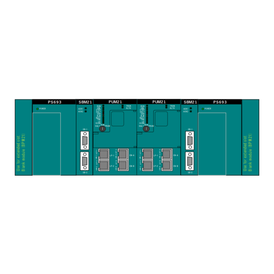
Names and Functions of Parts of the Controller The part names and functions of controller modules PUM21, serial bus interface module SBM21, and power module PS693 of the unified controller nv series type2 light controller are described. ■ Controller modules PUM21 ①... - Page 22 Chapter 1 On Installing type2 light Controllers ① Controller status display LED This displays the operation status of the controller module. ② Operation mode key switch This is used to set the operation mode. ③ Maintenance cover This is not used usually. ④...
- Page 23 Sets lower-order digits (0 - F) of LSD STN-L STN-L of IP address in hex. ・The switch is set to ‘00’ when out of manufacture. ・The switch cannot set to ‘00h’ or ‘FFh’. Unified Controller nv series type2 light Controller Unit Instruction Manual...
- Page 24 (Note) Check the error log at error status. About the checking method, refer to “7.2 Trouble Details Checks” in this manual. About the function of controller module, refer to 6F8C1576 「Unified Controller nv Series type 2 light Function Manual」. 6F8C1575...
-
Page 25: Part Names And Functions Of Serial Bus Interface Module
This is used to connect the serial bus 2. Table 1-5 Serial bus interface module LEDs Name Color Meaning Remark ACK1 Green Serial bus 1 transmission in progress ACK2 Green Serial bus 2 transmission in progress Unified Controller nv series type2 light Controller Unit Instruction Manual... -
Page 26: Part Names And Functions Of Power Module
Never touch the terminal. Prohibited Failure to do so may cause an electric shock. Precautions for using the power module ・This power module is dedicated to unified controller nv series CAUTION type1 and type2 controllers. Do not use it independently for any Mandatory other purposes. - Page 27 This is the neutral point of the primary power side line filter (grounding terminal). ⑥ Frame ground terminal (FG) This is connected to the frame (grounding terminal). This is connected to the internal circuit SG (signal ground) via a capacitor. Unified Controller nv series type2 light Controller Unit Instruction Manual...
-
Page 28: System Configuration
Base unit BUM22 Single/duplex chassis extended slot x 1 Rear mounted, Duplexed power support Power module PS693 100 - 240VAC (85 - 264V) power 5V-7A Controller module PUM21 nv series type2 light controller Serial bus interface module SBM21 SBIF adapter 6F8C1575... - Page 29 Rear mounted, Duplexed power support Power module PS693 100 - 240VAC (85 - 264V) power 5V-7A Controller module PUM21 nv series type2 light controller Serial bus interface module SBM21 SBIF adapter Unified Controller nv series type2 light Controller Unit Instruction Manual...
- Page 30 Chapter 1 On Installing type2 light Controllers Configuration with TC-net I/O connection ■ The type2 light controller connects TC-net I/O in a single loop configuration. I/O single configuration P U M 2 1 ...
- Page 31 TC-net I/O module Figure1-7 1-chassis duplex configuration and I/O duplex configuration ・ For the connection of the TC-net I/O module, see “High-speed Serial I/O System TC-net I/O Instruction Manual” (6F8C5098). Unified Controller nv series type2 light Controller Unit Instruction Manual...
- Page 32 Chapter 1 On Installing type2 light Controllers ■ Configuration with intelligent I/O connection An SBIF adapter is installed and inserted in the extended slot in the configuration with the intelligent I/O connection. (1) Intelligent I/O connection in a single controller configuration Loop A Loop A Loop B ...
- Page 33 Format BL7 (max 30m) left-hand figure SBIF1/2 installation Installation of two units PI/O module (max 14 units) I/O bus cable (max 5m) Terminal connector Figure 1-9 Duplex Intelligent I/O configuration Unified Controller nv series type2 light Controller Unit Instruction Manual...
-
Page 34: Installation Condition
Chapter 1 On Installing type2 light Controllers Installation Condition Use the product under the following installation condition. Do not install, store and use the equipment under CAUTION the following environment • Dusty place Prohibited • Place where corrosive gas (SO S) and flammable gas are generated •... - Page 35 ◆Note Avoid installing the unified controller nv series in the following places. ・ Place where the ambient temperature exceeds the range from 0 to 55°C (The temperature on the board gets close to the ambient temperature while it is stored.) ・...
- Page 36 Chapter 1 On Installing type2 light Controllers Power condition ■ Do not use other power module than PS693 for the controller unit Table 1-10 PS693 Power specification Item Specification Remark AC100-240V Rated voltage AC85-264V Allowable range of voltage 50/60Hz Rated frequency 47-53/57-63Hz Allowable range of frequency Allowable instantaneous...
-
Page 37: Grounding Of The Controller
It is ideal to ground the controller unit separately from the power system and ground two or more controller units to a single point. Unified controller nv series are designed to be noise-proof taking the actual application into consideration and the equipment is fully noise-proof. - Page 38 Chapter 1 On Installing type2 light Controllers ■ Grounding method Installing the control board nv series nv シリ ーズ The ground current passing from the 動力盤 連結盤の場合、 高周波機器や動力盤から流れ Power board controller コント ローラ high-frequency devices and the power board る接地電流が、...
- Page 39 This is the grounding terminal of the controller unit. The metal part of the base unit has the same electric potential as that of the FG terminal. Be sure to ground them at a single point for anti-static measures, security and safety reasons. Unified Controller nv series type2 light Controller Unit Instruction Manual...
- Page 40 Chapter 1 On Installing type2 light Controllers 6F8C1575...
- Page 41 Chapter 2 Installing/Uninstalling Install each module to base units comprising the controller unit. Implement the controller unit to the chassis. Before Starting the Work ········································· 25 Implementation to the chassis·································· 26 Grounding of the Controller and I/O Units ·················· 27 Installing the Base Unit ············································...
- Page 42 Chapter 2 Installing/Uninstalling Install the power module, controller module, CAUTION system bus module, TC-net I / O module to the Mandatory Mandatory base unit. Failure to observe it may cause an electric shock, an injury and a trouble. Do not use it alone or for other purposes.
-
Page 43: Before Starting The Work
(1) Do not disassemble the equipment. The equipment may fail. CAUTION (2) Be sure to turn off the power before the work. Failure to Prohibited do so may cause damage due to burn or electric shock. Unified Controller nv series type2 light Controller Unit Instruction Manual... -
Page 44: Implementation To The Chassic
Chapter 2 Installing/Uninstalling Implementation to the Chassis An example of installing the controller unit is shown in Figure 2-2. The figure illustrates the installation of the controller unit, power distribution unit and terminal block unit I/O system power unit External power unit ... -
Page 45: Grounding Of The Controller And I/O Units
The best way to ground the controller unit is to provide a dedicated ground separate from the power system and use a single point ground for two or more controller units. The nv series unified controllers are designed to be noise-proof taking the actual application into consideration and the equipment itself is sufficiently noise-proof. -
Page 46: Installing The Base Unit
Chapter 2 Installing/Uninstalling Installing the Base Unit Pay attention to the following items to install the base unit. For installing the base unit for TC-net I/O, refer to “TC-net I/O Instruction Manual” (6F8C1240). For installing the intelligent I/O, refer to “Intelligent PI/O Instruction Manual” (6F8C0779). Precautions for installing the base unit for type2 light controllers ■ ... -
Page 47: Installing/Uninstalling The Module
(4) Properly connect and firmly secure the connectors, cables and modules to the base unit using fixing tools such as screws. Check the omission and loose connection. If the screw is not sufficiently tightened, failure or malfunction may be caused by vibration. Unified Controller nv series type2 light Controller Unit Instruction Manual... - Page 48 Chapter 2 Installing/Uninstalling ■Procedure to install the controller module (1) Turn off the power of the type2 light controller. Also turn off the external power supply to the I/O module. (2) Mount the base unit on the vertical panel of the control board. (Refer to 2.4 “Installing the Base Unit.”) (3) Confirm the slot for mounting the base unit of the module.
- Page 49 (7) Check that the orange lock is completely set. Lock (8) Connect the required cables. Remark (1) Remove the connector cover, provided at the factory for shipment, to connect the cable. Unified Controller nv series type2 light Controller Unit Instruction Manual...
- Page 50 Chapter 2 Installing/Uninstalling ■Procedure to install the power module (1) Turn off the power of the type2 light controller. Also turn off the external power supply to the I/O module. (2) Mount the base unit on the vertical panel of the control board. (Refer to 2.4 “Installing the Base Unit.”) (3) Confirm the slot for mounting the base unit of the module.
- Page 51 Remark (1) After mounting the module on the base by fastening the screw, secure the base during transportation and storage so that the module can be installed vertically. Unified Controller nv series type2 light Controller Unit Instruction Manual...
- Page 52 Chapter 2 Installing/Uninstalling ■Procedure to install the serial bus interface module (1) Turn off the power of the type2 light controller. Also turn off the external power supply to the I/O module. (2) Mount the base unit on the vertical panel of the control board. (Refer to 2.4 “Installing the Base Unit.”) (3) Confirm the slot for mounting the base unit of the module.
- Page 53 Protrusion (b) While lightly pressing the protrusion, remove the cover by pulling the lower part of the cover. (Note) Take the above steps in reverse for mounting the cover. Unified Controller nv series type2 light Controller Unit Instruction Manual...
- Page 54 Chapter 2 Installing/Uninstalling 6F8C1575...
- Page 55 Chapter 3 Connecting Devices This chapter describes cable connection to the connectors of the external I/O terminal block of the power module for the control unit and the control unit. Power Wiring ································································· 38 Connection of TC-net I/O Loop Cable ································ 42 Connecting the Intelligent I/O···········································...
-
Page 56: Power Wiring
Chapter 3 Connecting Devices Power Wiring Observe the precautions listed below for wiring the type2 light controller. For the wiring of TC-net I/O, refer to “TC-net I/O Instruction Manual” (6F8C1240). For the wiring of the intelligent I/O, refer to “Intelligent PI/O Instruction Manual (6F8C0779). Ground the equipment. - Page 57 130 V in the 100 VAC line, or 260 V in the 200 VAC line. Basic unit Shield Ferrite core Noise filter transforme Two turns 100/240 VAC Figure 3-1 An example of recommended wiring for AC power Unified Controller nv series type2 light Controller Unit Instruction Manual...
- Page 58 Chapter 3 Connecting Devices ■ Wiring the power module of the type2 light controller 24V output 24VDC (The sum of internal 3.3V/5V and 24V output should be within 35W.) contact output Input power 100-240VAC フェライトコア Ferrite core 2 ターン Two turns Figure 3-2 Wiring power module PS693 *1: Line filter ground (LG) 5000 pF or less ...
- Page 59 Be sure to insert a circuit breaker in the input power line to turn off the power of PS693 separately. When replacing the failed module, open the circuit breaker for the line before staring the work. Unified Controller nv series type2 light Controller Unit Instruction Manual...
-
Page 60: Connection Of Tc-Net I/O Loop Cable
Chapter 3 Connecting Devices Connection of TC-net I/O Loop Cable Connect the TC-net I/O loop cable to the TC-net I/O loop connector (RJ45) of the controller module. ■ Connecting the TC-net I/O loop cable ・Connect the controller unit and TC-net I/O nodes by connecting LP2 and LP1 with the TC-net I/O loop cable in order from the smallest node number. - Page 61 TRK LP SCAN RUN HALT PRUN EN-A LP-1 To TC-net I/O connector LP1 of LP-2 EN-B TC-net I/O adapter Figure 3-5 Connection of TC-net I/O loop cable (Duplex configuration) Unified Controller nv series type2 light Controller Unit Instruction Manual...
-
Page 62: Connecting The Intelligent I/O
Chapter 3 Connecting Devices Connecting the Intelligent I/O Dedicated cable Serial bus Bus 1 connector Junction Intelligent I/O terminal block Serial bus Bus 2 connector Junction Intelligent I/O terminal block Figure 3-6 Connecting the intelligent I/O 6F8C1575... -
Page 63: Ethernet Connection
ONL HLTH STBY HALT ERR ALM BATT TRK LP SCAN RUN PRUN HALT Dedicated cable Ethernet loop A EN-A LP-1 EN-B LP-2 Ethernet loop B Figure 3-7 Ethernet connection Unified Controller nv series type2 light Controller Unit Instruction Manual... - Page 64 Chapter 3 Connecting Devices 6F8C1575...
- Page 65 Chapter 4 Starting and Stopping Check the switch setting of the controller module and start or stop the controller unit. Checking the Switch before Starting ························· 48 Installing the Battery to the Controller Module ··········· 50 How to Start the Controller ······································ 51 The Status of LED when the Controller is Started ·······...
-
Page 66: Checking The Switch Before Starting
Chapter 4 Starting and Stopping Checking the Switch before Starting The controller module has the operation mode switch and nV-Tool Ethernet IP address setting switch. Check if these switches are correctly set. ■ Operation mode key switch Table 4−1 Operation mode key switch Key position Description Key switch... - Page 67 Sets lower-order digits (0 - F) of LSD of IP STN-L STN-L address in hex. ・The switch is set to ‘00’ when out of manufacture. ・The switch cannot set to ‘00h’ or ‘FFh’. Unified Controller nv series type2 light Controller Unit Instruction Manual...
-
Page 68: Installing The Battery To The Controller Module
Chapter 4 Starting and Stopping Installing the Battery to the Controller Module The controller module is shipped from a plant with a battery attached instead of being built in. Attach the battery before using it. See “8.4 Replacing the battery” for the installing procedure. Mount the battery before using the equipment. -
Page 69: How To Start The Controller
4.3 How to Start the Controller How to Start the Controller Start the nv series type2 light controller according to the following procedure: Turn on the power with the operation mode key switch of the controller module set to HALT. -
Page 70: The Status Of Led When The Controller Is Started
(Note) Check the error log at error status. About the checking method, refer to “7.2 Trouble Details Checks” in this manual. About the function of controller module, refer to 6F8C1576 「Unified Controller nv Series type 2 light Function Manual」. 6F8C1575... -
Page 71: How To Stop The Controller
4.5 How to Stop the Controller H ow to Stop the Controller Stop the nv series type2 light controller according to the following procedure: Turn the operation mode key switch of the controller module to HALT. Note: In the case of duplex constitution, set both primary and secondary to "HALT". - Page 72 Chapter 4 Starting and Stopping 6F8C1575...
- Page 73 Chapter 5 Program Download Download programs created with nV-Tool to the controller unit. ...
- Page 74 Chapter 5 Downloading a Program Download programs to the controller unit according to the following procedure. Connect nV-Tool to the controller unit. Connect it directly via USB to controller module or via the control LAN. Set communication with the controller unit with nV-Tool. About the setup method, please refer to nv-Tool setup manual (6F8C1291) 「Section2 Setup V-tool」...
- Page 75 ・ Divided download Specify “configuration”, “programs” or “global variables” to download them without clearing the memory. Click Next button. The download destination setting screen is displayed. Unified Controller nv series type2 light Controller Unit Instruction Manual...
- Page 76 Chapter 5 Downloading a Program Check the controller of the download destination. When the divided download is selected in step the download target conformation dialog is displayed. Check required items. Click Next button.
- Page 77 Set the controller to RUN (operating condition). The controller starts operation. Remark ・ Even if the batch download finishes, the operation mode of the controller stays HALT. HALT may transition only to RUN. Unified Controller nv series type2 light Controller Unit Instruction Manual...
- Page 78 Chapter 5 Downloading a Program 6F8C1575...
- Page 79 Chapter 6 Operation When the power of the controller is turned on and programs have been downloaded, the controller is ready to operate. Then, you can start the operation. View the controller status display LED to change the operation mode switch while the controller is operating.
- Page 80 Chapter 6 Operation ■ Changing the operation mode using the operation mode key switch Table 6-1 Changing the operation mode key switch Switch position Operation HALT Selecting HALT from other position changes to the HALT mode. If you turn on the power in the HALT condition, the controller starts in the HALT mode.
- Page 81 About the checking method, refer to “7.2 Trouble Details Checks” in this manual. About the function of controller module, refer to 6F8C1576 「 Unified Controller nv Series type 2 light Function Manual 」 Unified Controller nv series type2 light Controller Unit Instruction Manual...
- Page 82 Chapter 6 Operation 6F8C1575...
- Page 83 Chapter 7 Troubleshooting When a failure occurs in the controller, the controller unit or other equipment indicates it using the status display LEDs. If you suspect that the controller or system is at fault, check the error details and take action to recover from the failure. If Failure Suspected ················································...
-
Page 84: If Failure Suspected
Output module may be faulty. synchronous with operation of the Go to "●Output signal check". system or a function? Contact the Toshiba's service representatives. Figure 7-1 Procedure of checks in occurrence of failure Before removing or installing the module, terminal block, or CAUTION cable, be sure to keep power off. - Page 85 POWER LED goes out. Figure 7-2 Power system check procedure Remark ・ When removing or reinstalling a cable or module, make sure that power is kept off throughout the process. Unified Controller nv series type2 light Controller Unit Instruction Manual...
- Page 86 Chapter 7 Troubleshooting ■ Controller module check If the RUN LED of the controller module does not light up although POWER LED of the power module remains lit up, check the following: 点滅/ 点灯 ERRのL EDが点滅または点灯して Is ERR LED blinking or on? If the LED is still blinking or remains lit up, the 電源を再投入しても...
- Page 87 常になるのか of I/O unit? have occurred on a cable or the I/O ケーブルの異常またはT C - ne t I/ Oイ ンタ フ interface. ェ ースの異常も考えられます。 Figure 7-4 Input signal check procedure Unified Controller nv series type2 light Controller Unit Instruction Manual...
- Page 88 ・ If the fuse has blown out, be sure to examine and eliminate the cause. If you replace the fuse without eliminating the cause and then turn on the power again, destruction of the module may proceed. If you cannot identify the cause of blowout, consult with Toshiba with the module as it is. 6F8C1575...
- Page 89 In addition to the above cases, stable operation of the system will not be guaranteed if the ambient temperature is outside the range required in the specification. Pay special attention also to the environmental conditions. Unified Controller nv series type2 light Controller Unit Instruction Manual...
-
Page 90: Trouble Details Checks
Chapter 7 Troubleshooting Trouble Details Checks You can use the controller status display LED and nV-Tool log information about the controller in order to check the trouble occurring in the controller. ■ Checks with the controller module's controller status display LEDs When the RUN or ERR LED of the controller front panel remains stopped in one of the cases listed in Table 7-1, this indicates that an error has occurred. - Page 91 7.2 Trouble Details Checks Figure 7-6 Product tree In the nV-Tool product tree, select the menu bar > File > System View to start System View. Figure 7-7 System View Unified Controller nv series type2 light Controller Unit Instruction Manual...
- Page 92 Chapter 7 Troubleshooting From System View, select the main slot number of the appropriate controller. Then, select the menu bar > nV-Tool > System Logs. System Logs appears. System Logs shows the error, event, and transmission logs. Update the log : To view the latest logs, click the Read Log icon or select the menu bar >...
- Page 93 Click Error Reset. A confirmation dialog box appears. Select Yes. The error reset finishes, and the controller enters the HALT mode. Perform the desired operations such as program amendments in this mode. Unified Controller nv series type2 light Controller Unit Instruction Manual...
- Page 94 Chapter 7 Troubleshooting Then start RUN again. Change the controller's operation mode key switch to HALT once before switching to RUN. Alternatively, run the RUN command in Set Run Mode on nV-Tool. Remark ・ Even if the calendar has gone abnormality, the error logs are registered; however, the date and time are displayed in the form of “date-time”...
- Page 95 I/O Node Status button, or double-click the I/O status cell of the appropriate controller. I/O Node Status appears. In Figure 7-13, you can see that the I/O status of I/O node No. 3 is abnormal. Figure 7-13 I/O Node Status Unified Controller nv series type2 light Controller Unit Instruction Manual...
- Page 96 Chapter 7 Troubleshooting Viewing I/O status details Select the appropriate I/O node number of I/O Node Status. Click the I/O Module Status button, or double-click the I/O status cell of the appropriate I/O node number. I/O Module Status appears. In Figure 7-14, you can see that the I/O module DO934 of Slot No. 1 of I/O Node No. 3 is faulty.
- Page 97 Chapter 8 Maintenance and Inspection To maintain normal operation of the controller, you should perform daily and periodic inspections. In addition, you should also replace consumables such as the battery. Daily Inspections ···················································· 80 Periodic Inspections ··············································· 81 Service Parts ·························································· 82 Replacing the Battery ··············································...
-
Page 98: Daily Inspections
Chapter 8 Maintenance and Inspection Daily Inspections Check the items below daily while the controller is in operation. If you find smoke or catch an unusual odor, power CAUTION off the controller. Mandatory Fire or explosion may result. Remark ・... -
Page 99: Periodic Inspections
Check whether the battery connector is connected firmly. Must not be loose. Check the Change master and slave mode by nv-Tool and RUN normally Duplex confirm that MASTER-RUN, SLAVE-RUN operate function normally Unified Controller nv series type2 light Controller Unit Instruction Manual... -
Page 100: Service Parts
Chapter 8 Maintenance and Inspection Service Parts To recover from trouble early, it is recommended that at least the service parts below be prepared. Replace the fuse and the battery with the WARNING specified product. Mandatory Using other products may cause a fire and a trouble. Table 8-3 Service parts Product name Amount... -
Page 101: Replacing The Battery
Complete the battery replacement process within 3 min. Open the front battery cover and take out the battery from battery holder. Pull out the connector (brown) for the battery module frontwards. Unified Controller nv series type2 light Controller Unit Instruction Manual... - Page 102 Chapter 8 Maintenance and Inspection Insert the connector (brown) for the new battery module into the controller connector. Mount the battery in the battery module. Take care do not sandwich the cable of the battery between the main body and maintenance cover. ...
- Page 103 A short circuit between the positive and negative electrodes of the lithium battery may generate smoke or cause fire. Dispose of the lead wires or the like without cutting or disassembling them and without any short circuit between the positive and negative electrodes. Unified Controller nv series type2 light Controller Unit Instruction Manual...
-
Page 104: Disposing Of The Module
Chapter 8 Maintenance and Inspection Disposing of the Module When disposing of the module, comply with the regulations of the local government. 6F8C5572... - Page 105 Appendix A Specification A.1 General Specification ·············································· 88 A.2 Power Module Specification ····································· 90 A.3 Controller Module Specification ······························· 92 A.4 Serial Bus Interface Module Specification ·················· 93 A.4 Base Unit Specification ··········································· 93 A.6 Life-time Components ············································· 94 A.7 List of TC-net I/O Modules and Other Related Modules ·······...
-
Page 106: General Specification
Appendix A Specification General Specification Table A-1 General specification Item Specification Remarks 0°C to 55°C; 40°C or less on average over 24 hours (Note 1) Operating ambient temperature Storage temperature -40 to 70°C Operating ambient 10% to 95%RH, Level RH2 (no condensation) (Note 2) relative humidity Dust... - Page 107 The lifetime components include memory backup battery, aluminum electrolytic capacitor, relay, fuse, photocoupler. Section A.4 contains information about main lifetime components including the replacement cycles. Unified Controller nv series type2 light Controller Unit Instruction Manual...
-
Page 108: Power Module Specification
Appendix A Specification Power Module Specification Table A-2 Power module specification Item Specification Remarks Model PS693 Rated voltage 100 - 240VAC Voltage tolerance 85 - 264VAC range Rated frequency 50/60Hz Frequency 47-53/57-63Hz tolerance Permitted duration 10 ms or less of instantaneous power failure Permitted 10%or less... - Page 109 Do not use Mandatory it independently for any other purposes. ・Take at least one second from power-off to subsequent power-on; otherwise, the module may not start properly or malfunction. Unified Controller nv series type2 light Controller Unit Instruction Manual...
-
Page 110: Controller Module Specification
Appendix A Specification Controller Module Specification Table A-3 Controller module specification (hardware) Item SPECIFICATION Remarks PUM21 Model Substrates sheets SH7730(SH4A) ×2 32bit Bus width 50MHz Operating frequency 2.5A (Max.) Current consumption Slot width 2 slots occupied Weight About 360g Excluding protrusions Outside dimensions Approx.70.6W×135.0H×105.0Dmm RUN, ONL, STBY, HALT, ERR,... -
Page 111: Serial Bus Interface Module Specification
Table A-5 Base Unit specification Content Specification Name BUM22 Backplane System Bus, Tracking Bus Duplication Duplication in one base unit Dimension 416.5W×135.0H×29.0D (mm) (Excluding protrusions ) Weight About 0.9kg(Only base unit) Unified Controller nv series type2 light Controller Unit Instruction Manual... -
Page 112: Life-Time Components
Appendix A Specification Life-time Components ■ Battery (Memory backup battery) To keep the backup and calendar data retained, replace the memory backup battery every 90 days of the total period of power outage or every 5 years when the annual average temperature is 30 C or less, or every 2 years when the annual average... -
Page 113: List Of Tc-Net I/O Modules And Other Related Modules
LP900 series exclusive interface (electrical) SA941 Signal conditioner interface (electrical) SA942 Signal conditioner interface (optical) SA961 Duplex TC-net I/O interface (electrical) SA962 Duplex TC-net I/O interface (optical) PA912 PROFIBUS-DP master module (optical) Unified Controller nv series type2 light Controller Unit Instruction Manual... -
Page 114: List Of Intelligent I/O Modules And Other Related Modules
Appendix A Specification Table A-8 TC-net I/O module Model Outline Channel points insulation DI934 24VDC 5 mA digital filter None DI934I 24VDC 4mA digital filter None DI935 24VDC 4 mA digital filter None DO934 24VDC 100 mA, sink output None DO935 24VDC 50mA, sink output None... -
Page 115: List Of Intelligent I/O Modules And Other Related Modules
Terminal block unit for analog input (F series) (vertical DIN rail) UTBA8 Terminal block unit for analog output (F series) (vertical DIN rail) UDBU2 Terminal block unit for digital module (F series) (vertical DIN rail) Unified Controller nv series type2 light Controller Unit Instruction Manual... - Page 116 Appendix A Specification Table A-12 Intelligent I/O modules Model Outline Channel points insulation SAI01/ Analog input module (mV/V input) None SAI012 SAI02/ Analog input module(1-5VDC input) Provided SAI022 SAI03/ Analog input module(1-5VDC input), with a distributor Provided SAI032 STC01/ Analog input module (thermocouple input) Provided STC012 SRT01/...
-
Page 117: List Of Current Consumptions And Weights By Module
BU902A, BU903A, BU904A are the modules used for common bar or short bar for addition. Other specifications are the same as the modules without `A'. The modules without `A' cannot add the common bar or short bar to modules. Unified Controller nv series type2 light Controller Unit Instruction Manual... - Page 118 Appendix A Specification Table A-15 TC-net I/O module / IO adapter External 24 Internal 24 Module VDC current Weight Model Outline supply Remarks consumption (Or less) name current (max) (max) SA911 TC-net I/O(electrical) 400mA 250g Adapter - SA912 TC-net I/O(optical) 400mA 250g -...
- Page 119 120mA 200g - SAOF1 16-ch analog output (F series) 50mA 200g - SDIF1 32-pt digital input (F series) 65mA 200g - SDOF1 32-pt digital output (F series) 80mA 200g - Unified Controller nv series type2 light Controller Unit Instruction Manual...
-
Page 120: Cable
Appendix A Specification Table A-17 Intelligent Terminal block Weight Model Outline less) USCB1 For SBIF1/SBIF2 (vertical DIN rail) 300g USCB2 For SBIF1/SBIF2 (horizontal DIN rail) 300g USCB3 For SSIF1 (horizontal DIN rail) 300g UTBA1 For analog module (vertical DIN rail) 750g UTBA2 For SAI02, SAI03, SRT01 and SAO02 (vertical DIN rail) - Page 121 Appendix B Outline Drawing B.1 Base Unit ····························································· 104 B.2 Power Module ······················································ 105 B.3 Controller Module ················································· 106 B.4 Serial Bus Interface Module ··································· 107 ...
-
Page 122: Base Unit
Appendix B Outline Drawing Base Unit 6 402.5 8 2 9 . 0 2 9 416.5 Figure B-1 Outside dimensions of base unit BUM22 6F8C1575... -
Page 123: Power Module
Power Module 70.5 104.5 7 0 . 5 1 0 4 . 5 Figure B-2 Outside dimensions of power module PS693 Unified Controller nv series type2 light Controller Unit Instruction Manual... -
Page 124: Controller Module
Appendix B Outline Drawing Controller Module PUM21 RUN TRUN ONL HLTH STBY HALT ERR ALM BATT TRK LP SCAN LP−1 EN−A LP−2 EN−B 7 0 . 6 70.6 1 0 5 . 0 105... -
Page 125: Serial Bus Interface Module
Serial Bus Interface Module Figure B-4 Outside dimensions of Serial Bus Interface Module SBM21 Unified Controller nv series type2 light Controller Unit Instruction Manual... - Page 126 Appendix B Outline Drawing 6F8C1575...
-
Page 127: Dc Input Modules
Appendix C Notes on Applying the I/O Modules C.1 DC Input Modules ················································· 109 C.2 AC Input Modules ·················································· 115 C.3 DC Output Modules ················································ 118 C.4 AC Output Modules ··············································· 121 C.5 Analog Input Modules ··········································· 122 C.6 Analog Output Modules ········································· 123 ... - Page 128 Appendix C Notes on Applying the I/O Modules Introduce the notes on applying TC-net I/O module in this section. About the details of TC-net I/O modules, refer to 6F8C1240 「High-speed Serial I/O System TC-net I/O Instruction Manual」 and 6F8C1381 「Industrial TC-net I/O System Instruction Manual」. About the Serial PI/O modules, refer to 6F8C0779 「Serial PI/O System Intelligent PI/O Instruction Manual」.
- Page 129 LED, disabling input OFF to be read. In this case, install a bleeder resistor to lower the input impedance. Input module 入力モジュール Figure C-3 Switch with LED Unified Controller nv series type2 light Controller Unit Instruction Manual...
- Page 130 Appendix C Notes on Applying the I/O Modules (Example of selecting bleeder resistor R) Input module DI934 (input impedance approx. 4.6 kΩ, OFF voltage 6.0 V) Input voltage V = 24 VDC Suppose that the switch leakage current IL = 2mA. Let R [kΩ] and P [W] be the resistance of the bleeder resistor and the wattage, respectively.
- Page 131 CPU scanning as well as response lag in output and input. For the hardware, a backflow prevention diode is required to prevent input errors caused by the peripheral circuit. (4x4 input is shown in the following figure.) Unified Controller nv series type2 light Controller Unit Instruction Manual...
- Page 132 Appendix C Notes on Applying the I/O Modules Input module ・ module ・Output For example, if contact a is ON, the change timing from Output 0 to Input 0 is as follows: CPU scanning cycle Output 0 (internal) Output 0 (external) Input 0 (external) Input 0 (internal) ...
-
Page 133: Ac Input Modules
Let R [kΩ] be the resistance of the bleeder resistor to be selected. Let P [W] be the wattage. The following is satisfied in this case: 8[kΩ]×R 35[V] × <20[V] 8[kΩ]+R 8[kΩ] Hence, R<11 [kΩ] → R = 10 [kΩ] Unified Controller nv series type2 light Controller Unit Instruction Manual... - Page 134 Appendix C Notes on Applying the I/O Modules Where (100[V]) × (2.5〜3) ≒ 3 [W] 10[kΩ] In addition, you must make sure that when the bleeder resistor is selected as above, the output current at sensor ON time is within the tolerance. Sensor output current If a log external wiring of AC input is routed, an induced current may flow from the charging wiring to the open-circuited wiring because of the capacity across the...
- Page 135 OFF delay timer) is effective. The figure below shows an example of program applying OFF delay timer to AC input “X0003.” 100ms 100ms X0003 R1003 Figure C-9 Program timing example Unified Controller nv series type2 light Controller Unit Instruction Manual...
-
Page 136: Dc Output Modules
Appendix C Notes on Applying the I/O Modules DC Output Modules The DC output modules require that power to drive the output transistor be supplied externally. Connect the voltage within the rated load voltage criterion to the predefined terminals for each of the common terminals. (Refer to the TC-net I/O Instruction Manual: Module Individual Specification.) If connection made with the polarity of the power supply inverted, the module may fail. - Page 137 To restrict the rush current, it is useful to take measure where the resistor is connected in parallel to the load, or a dark current flowing through the lamp load with the resistor installed between the output terminals. Unified Controller nv series type2 light Controller Unit Instruction Manual...
- Page 138 Appendix C Notes on Applying the I/O Modules If the inductive load is connected to an output module, a transient voltage with a relatively large energy is generated at OFF time. This surge voltage is absorbed with Diode D mentioned above to protect the transistor. If the external wiring is used for routing, this surge voltage may have an adverse affect on other signal systems.
-
Page 139: Ac Output Modules
The AC output module does not have the zero cross function. OFF-to-ON change occurs regardless of the phase of the load voltage. However, at ON-to-OFF change time, the load current changes near zero. For the load response, also take this into consideration. Unified Controller nv series type2 light Controller Unit Instruction Manual... -
Page 140: Analog Input Modules
Appendix C Notes on Applying the I/O Modules Analog Input Modules For the analog input signal line, use a shielded twisted pair cable and wire it at the minimum distance. Ground the cable shield at the analog input module. To satisfy the requirements in the EMC instructions, connect the shielded cable at the minimum (i.e., within 3 cm) distance to the chassis that contains the installed nv series type2 light controller. -
Page 141: Analog Output Modules
The converted value may be unstable, depending on the voltage state of the 24 V power supply. If the converted result is unstable, replace the analog external power supply with the dedicated power supply. Unified Controller nv series type2 light Controller Unit Instruction Manual... - Page 142 Appendix C Notes on Applying the I/O Modules 6F8C1575...
- Page 143 Appendix D Migration Method Migration Method ··························································· 125 ...
-
Page 144: Migration Method
Appendix D Migration Method This chapter explains the method of migrate to the type2 light controller by the system of Integrated Controller V series model 2000 L2PU22 (herein after called the”L2 controller”). About the L2 controller modules, refer to 6F8C0883 「Loop Controller L2 User's Manual - Basic Hardware」. About the details of TC-net I/O modules, refer to 6F8C1240 「High-speed Serial I/O System TC-net I/O Instruction Manual」... - Page 145 (Refer to “1.5 System Configuration”,”3.3 Connecting the Intelligent I/O”) Turn on the power of type2 light controller. Note ・About the setting the nv-Tool Refer to 6F8C1576 「Unified Controller nv Series type 2 light Function Manual」 and 6F8C1290 「Unified Controller nv series/Integrated Controller V series Engineering Tool 4 -Basic-Instructions」.
- Page 146 Appendix D Migration Method 6F8C1575...
- Page 147 Unified Controller nv Series type2 light Controller Unit Instruction Manual First edition in June 2015 Toshiba Corporation Social Infrastructure Systems Company Industrial System & Components Division 72-34 Horikawa-Cho, Saiwai-Ku, Kawasaki 212-8585, Japan ©Toshiba Corporation All Rights Reserved. 2015...
- Page 148 72-34 Horikawa-cho, Saiwai-ku, Kawasaki-shi, Kanagawa 212-8585, Japan 1575.1.1506...
Need help?
Do you have a question about the nv Series and is the answer not in the manual?
Questions and answers