
Related Manuals for Red Pitaya HAMlab 80-10 10W

Summary of Contents for Red Pitaya HAMlab 80-10 10W
- Page 1 Red Pitaya HAMlab Documentation Red Pitaya HAMlab Documentation HAMlab models that are covered by this user manual: HAMlab 80-10 10W HAMlab 160-6 10W Red Pitaya The manual is made on the site https://trcvr.ru...
- Page 2 Update HAMlab software Applications and Features 3.1. Oscilloscope with Signal Generator 3.2. Spectrum Analyzer 3.3. Logic Analyzer 3.4. Power SDR HAMlab 80-10 10W Specifications 4.1. SDR specifications 4.2. Measurement instruments specifications 4.3. General Electrical specifications 4.4. Mechanical specifications 4.5. HAMlab system architecture 4.6.
- Page 3 This product shall only be powered by an external power supply providing 13.8 VDC power supply that can provide at least 4A of constant power. The power supply used with Red Pitaya HAMlab must comply with relevant regulations and standards applicable in the country of use.
-
Page 4: Instructions For Safe Handling
1. Do not expose the product to any liquid, moisture, flammable materials or chemicals. 2. Do not expose the product to heat from any source. The Red Pitaya product is designed for reliable operation only at normal ambient room temperatures. -
Page 5: Quick Start
Red Pitaya HAMlab Documentation 2. Quick start Quick start 2.1. What is in the box 2.2. Other additional requirements 2.3. Start using HAMlab measurement instruments 2.3.1. Connecting the cables 2.3.1.1. Back panel connections 2.3.1.2. Front panel connections 2.3.2. Turning it on and start using measuring instruments 2.4. -
Page 6: What Is In The Box
DC power cord with Anderson Power Pole™ connector Ethernet cable USB 2.0 Cable - A-Male to Mini-B (only for HAMlab 80-10 10W) Rx filters bypass BNC cable 2.2. Other additional requirements In addition to the supplied accessories, software and cables supplied with the HAMlab, you will need to provide the following: ... - Page 7 Red Pitaya HAMlab Documentation Anderson Power Pole™ power connector (1) Ethernet connection (2) - connect the HAMlab to your local network using Ethernet cable. Note Other connections are at the moment not important, you can read more about them later in the Back panel controls and connections section.
- Page 8 Red Pitaya HAMlab Documentation 2.3.2. Turning it on and start using measuring instruments 1.) Turn on power supply, and press momentary power button on the HAMlab to turn it ON. Blue led on power button will turn on and after 30s HAMlab will be ready to use.
-
Page 9: Start Using Hamlab As Radio Station - Sdr
USB cable (3) - connect the HAMlab with the PC using USB 2.0 Cable - A-Male to Mini-B. USB cable will provide a way for PowerSDR software to use HAMlabs audio outputs. USB cable for audio is only required for HAMlab 80-10 10W model. Ethernet Connection (4) - connect the HAMlab to your local network using Ethernet cable HAMlab should be powered by DC 13.8V Power Supply that can provide at least 4 A of constant power. - Page 10 Red Pitaya HAMlab Documentation 2.4.1.2. Front panel connections Microphone (1) Note More information about compatibility of microphone, key and headphones and front panel connections in general can be found in the Front panel controls and connections section. Iambic Morse Code Paddle Keyer (2) Note Keyer is supported only with software 0.97-93 or later.
- Page 11 Red Pitaya HAMlab Documentation Congratulations, HAMlab is now ready for use, now let’s install Power SDR. Note Exiting this SDR WEB application will close the connection to Power SDR. 2.4.2. Power SDR installation and SDR configuration Click here to download Power SDR installation package.
- Page 12 Red Pitaya HAMlab Documentation 3. Follow the instructions of the setup routine and accept the license agreements if asked for. The manual is made on the site https://trcvr.ru...
- Page 13 Red Pitaya HAMlab Documentation The manual is made on the site https://trcvr.ru...
- Page 14 Red Pitaya HAMlab Documentation 4. At the end of the installation you are asked if you want to run PowerSDR software immediately, feel free to do so. The manual is made on the site https://trcvr.ru...
- Page 15 Red Pitaya HAMlab Documentation 5. PowerSDR software will start with the calculation of the FFT wisdom file, which will take a while depending on the CPU power of your computer. This is only done once, even after updating the software to a new version in the future: 6.
- Page 16 Red Pitaya HAMlab Documentation 7. Select the region where you are using your STEMlab, this is important due to the different frequency ranges your are allowed to transmit in the different countries all over the world: 8. Your initial setup is completed click finish.
-
Page 17: Alternative Networking For Hamlab
Red Pitaya HAMlab Documentation Note Power SDR software is described in Power SDR section. Optionally you can connect MIDI controller to your PC. MIDI controller can be used to control radio software parameters like frequency with physical knobs. 2.5. Alternative networking for HAMlab 2.5.1. - Page 18 Red Pitaya HAMlab Documentation 2.5.2. Wired 2.5.2.1. Local Area Network (LAN) This is the most common and recommended way of connecting and using your HAMlab. Your LAN network needs to have DHCP settings enabled which is the case in majority of the local networks, whit this, simple “plug and play”...
- Page 19 Red Pitaya HAMlab Documentation 2.5.2.2. Direct Ethernet cable connection It is possible to establish direct connection between your pc and HAMlab. For Windows 10 just connect HAMlab to your computer and access it using rp-xxxxxx.local/ method. Note Windows 7/8 users should install Bonjour Print Services, otherwise access to *.local addresses will not work.
- Page 20 Red Pitaya HAMlab Documentation b. Add new Ethernet connection (There is no need to create new network since you can set static IP settings on the existing network and skip all steps up to step 5. ) 3. Select “Ethernet” connection and press “Create” button 4.
- Page 21 Red Pitaya HAMlab Documentation d. DNS servers (can be left empty) and click “Save” button. Note Once you have this settings arranged, connect Ethernet cable between your HAMlab and PC, open web browser, in the web browser URL field input chosen HAMlab static IP (in our example it is 192.168.0.15) and press enter.
- Page 22 Red Pitaya HAMlab Documentation 2.5.3. Wireless 2.5.3.1. Wireless Network Connection This type of the connection will enable wireless connection to the HAMlab via your local WiFi network. In order to connect your HAMlab to the same WiFi network on which you have connected your PC/Laptop first you need to use LAN connection.
- Page 23 Red Pitaya HAMlab Documentation 4. When the USB WiFi dongle is plugged in, the system will recognize it and enabled additional settings. 5. Select Client Mode, Desired WiFi network, Insert password and click Connect. 6. When your HAMlab is connected the IP address will be shown on the user interface. This IP address is only for WiFi connection.
- Page 24 Red Pitaya HAMlab Documentation 2.5.3.2. Access Point mode This type of the connection is ideal if there is no LAN or WiFi network. HAMlab will simply create its own WiFi network on which users PC/Laptop or Tablet can be connected. Access Point mode is arranged via Network Manager application where you give the name to your HAMlab network and enable it.
-
Page 25: Unlocking Logic Analizer App
Red Pitaya HAMlab Documentation Note IP address in Access Point mode is always the same: 192.168.128.1 2.6. Unlocking Logic Analizer app Click here and log in with your account. If you are not registered yet, please do so! Click on MY RP in the right upper corner. - Page 26 Red Pitaya HAMlab Documentation 2.7.1. Windows 1. Insert SD card into your PC or SD card reader. 2. Download Win32 Disk Imager to your Desktop and unzip it. 3. Open unzipped folder, right-click on the Win32 Disk Imager, and select ‘Run as Administrator’.
- Page 27 Red Pitaya HAMlab Documentation 5. Under device box select the drive letter of the SD card. Note Be careful to select the correct drive; if you choose the wrong one you risk erasing data from the computer’s hard disk! You can easily see the drive letter (for example E:) by looking in the left column of Windows Explorer.
- Page 28 Red Pitaya HAMlab Documentation 6. Click Write and wait for the write to complete. 7. Exit the Imager. The manual is made on the site https://trcvr.ru...
- Page 29 Red Pitaya HAMlab Documentation 2.7.2. Linux 1. Insert SD card into your PC or SD card reader. 2. Run Disks application to format the SD card. The manual is made on the site https://trcvr.ru...
- Page 30 5. Write the image to the SD card with the following command : dd if=image_file of=/dev/sdb bs=1M Note Replace the red_pitaya_image_file with the name of the unzipped Red Pitaya SD Card Image and /dev/device_name is replaced with the path to the SD Card, usually it will be /dev/sdb. 6. Wait until the process has finished.
- Page 31 Red Pitaya HAMlab Documentation 2. Download Apple Pi Baker and unzip it. 3. Press “crtl” key and click on ApplePi-Baker icon, then click Open in order to run it. 4. Enter your admin password and click OK. 5. Select SD card drive. This can be recognized by the size of the card that is 4GB.
- Page 32 Red Pitaya HAMlab Documentation 7. Click “Restore Backup” button in order to write image to SD card. 8. It’s coffee time, application will show you Estimated Time for Accomplishment. 9. When operation is completed click “OK” and quit ApplePi-Baker. The manual is made on the site...
-
Page 33: Update Hamlab Software
Red Pitaya HAMlab Documentation FAQ: How to install HAMlab OS on MAC not using ApplePiBaker? 1. Now you have a brand new Micro SD card with latest HAMlab OS. Insert it into HAMlab with contacts facing up. 2. Power on Power Supply 3. -
Page 34: Manual Upgrade
Red Pitaya HAMlab Documentation 2. Click on the system icon. 3. Then click onto update icon. 4. Select ecosystem version and start OS updater 5. Follow the steps in the OS updater app in order to install new OS. Note OS update might cause your HAMlab desktop to freeze for a few minutes. -
Page 35: Applications And Features
Red Pitaya HAMlab Documentation 3. Applications and Features Applications and Features 3.1. Oscilloscope with Signal Generator 3.1.1. Features 3.1.2. Output 3.2. Spectrum Analyzer 3.2.1. Features 3.2.1.1. INPUTS 3.2.1.2. CURSORS 3.2.1.3. RANGE 3.2.1.4. PEAK DETECTION 3.2.1.5. WATERFALL PLOTS 3.2.1.6. AXIS CONTROLS 3.3. -
Page 36: Oscilloscope With Signal Generator
Red Pitaya HAMlab Documentation 3.1. Oscilloscope with Signal Generator This application will turn your HAMlab into a 2-channel Oscilloscope and 2-channel Signal generator. It is the perfect tool for educators, students, makers, hobbyists and professionals seeking affordable, highly functional test and measurement equipment. It enables generating and measuring electrical signals up to 50MHz. - Page 37 Red Pitaya HAMlab Documentation o slope Trigger modes: o auto, o normal and o single triggering Input calibration wizard Cursors Measurements Math operations Signal generator controls: o waveform, o amplitude, o frequency, o phase AUTO SCALE: Automatically sets up the Oscilloscope to best display the input signal.
- Page 38 Red Pitaya HAMlab Documentation INPUTS: On the right side of the Oscilloscope&Sig. Generator application interface the IN1 and IN2 channels are listed. By a simple click on the name of a channel (not the gear) the channel gets highlighted and you can simply control all the settings of the respective channel.
- Page 39 Red Pitaya HAMlab Documentation Frequency, Amplitude, Offset, Phase and Duty cycle. Various waveforms are available for output: SINE (sinus), SQUARE (rectangle) TRIANGLE (triangle), SAWU (rising saw tooth), SAWD (falling saw tooth), DC and PWM (Pulse Width Modulation).
- Page 40 Red Pitaya HAMlab Documentation CURSOR: This feature enables the user to easily get the data of relevant basic measurements such is: signal period, amplitude, time delay, amplitude difference between two points, time difference between two points and etc. NAVIGATE: When you have a lot of data to analyze, it is very important to get through them easily.
-
Page 41: Spectrum Analyzer
Red Pitaya HAMlab Documentation MEASUREMENTS: The menu can be found under the MEAS button. Here you can select up to 4 measured values in total, then provide the corresponding values. In the Operator field select the desired measurement and then set the Signal from which channel the value should be taken. - Page 42 Red Pitaya HAMlab Documentation Inputs / Cursors / Range / Axis control panel: This menu provides controls for inputs, cursors, and frequency range settings. Horizontal +/- buttons are used to select the span of the X (frequency) axis (zooming in/out). The vertical +/- buttons change the Y (amplitude)-axis range.
- Page 43 Red Pitaya HAMlab Documentation frequency value is shown corresponding to the place where the X cursors are set, and the amplitude value where the Y cursors are set. Cursor delta values are useful for measuring signal harmonics and relative ratios between amplitudes and frequencies.
-
Page 44: Logic Analizer
Red Pitaya HAMlab Documentation 3.2.1.5. WATERFALL PLOTS Waterfall plots are a different way of the signal spectrum representation where the color on the plot defines the signal amplitude for a certain frequency. The waterfall plot is also useful when enabling the representation of the signal spectrum in a time dependency. - Page 45 Red Pitaya HAMlab Documentation Apart from the actual graph, there are again 5 key areas/elements, in which the surface is divided: Auto: Resets the zoom and brings the trigger event in the middle of the graph. Run / Stop: Starts recording the input signals, and interrupts it when the recording is active.
- Page 46 Red Pitaya HAMlab Documentation By clicking the RUN button the recording is started. The status display informs you whether the process is still running (WAITING) or has already been completed (DONE). After finishing the acquisition, the results are displayed in a graph. Additional trigger options LOW and HIGH are used for the so called Patterned triggering.
-
Page 47: Power Sdr
Red Pitaya HAMlab Documentation Note On HAMlab OS releases before 0.97.100 Logic Analyzer application will be require to enter unlock code into our licensing system. Procedure can be access at Unlocking Logic Analizer app section. 3.4. Power SDR 3.4.1. Power SDR installation and SDR configuration... - Page 48 Red Pitaya HAMlab Documentation On Windows 10 you might get warning of Unknown Publisher you can proceed with installation by clicking on “more info” and then “Run anyway”. 3. Follow the instructions of the setup routine and accept the license agreements if asked for.
- Page 49 Red Pitaya HAMlab Documentation The manual is made on the site https://trcvr.ru...
- Page 50 Red Pitaya HAMlab Documentation The manual is made on the site https://trcvr.ru...
- Page 51 Red Pitaya HAMlab Documentation 4. At the end of the installation you are asked if you want to run PowerSDR software immediately, feel free to do so. 5. PowerSDR software will start with the calculation of the FFT wisdom file, which will take a while depending on the CPU power of your computer.
- Page 52 Red Pitaya HAMlab Documentation 7. Select the region where you are using your STEMlab, this is important due to the different frequency ranges your are allowed to transmit in the different countries all over the world: 8. Your initial setup is completed click finish.
- Page 53 Red Pitaya HAMlab Documentation 3.4.1.1. Power SDR configuration Audio configuration (only required for HAMlab 80-10 10W model) 3.4.1.2. Power SDR basic usage 3.4.1.2.1. Putting HAMlab into SDR mode 1. Turn on power supply, HAMlab will start automatically. Next time you can momentary press on the power button to turn it on/off.
- Page 54 Red Pitaya HAMlab Documentation HAMlab application page should appear 3.4.1.2.2. Connecting Power SDR with HAMlab The manual is made on the site https://trcvr.ru...
- Page 55 Red Pitaya HAMlab Documentation 3.4.1.2.3. Receiving 3.4.1.2.4. Transmitting 3.4.1.3. Credits Original developer of sdr-transceiver-hpsdr web application is Pavel Demin. Original developer of PowerSDR is FlexRadio Systems. Repositories used for our builds: https://github.com/RedPitaya/PowerSDR_HPSDR_mRX_PS https://github.com/RedPitaya/red-pitaya-notes The manual is made on the site...
-
Page 56: Hamlab 80-10 10W Specifications
Red Pitaya HAMlab Documentation 4. HAMlab 80-10 10W Specifications 4.1. SDR specifications 4.1.1. Highlights Architecture: direct sampling / internal high performance 14-bit A/D and D/A 125 Msps converters (no sound card required) Band coverage: All band receiver with 5 bands transmitter (80, 40, 20, 10 m) -
Page 57: Measurement Instruments Specifications
Red Pitaya HAMlab Documentation 4.2. Measurement instruments specifications 4.2.1. Oscilloscope Input channels Input channels connector Bandwidth 50 MHz Resolution 14 bit Memory depth 16384 Samples Max. Sampling Rate 125 MS/s Input range +/- 1 V or +/- 20 V Input coupling... -
Page 58: General Electrical Specifications
Red Pitaya HAMlab Documentation Note Acquired data is compressed therefore the size of data than can be captured depends on activity of signal on LA inputs. For I2C, SPI & UART signals 1MS is typical sample depth. All instrumentation applications are WEB based and don’t require the installation of any native software. Users can access them via a browser using their smartphone, tablet or a PC running any popular operating systems (MAC, Linux, Windows, Android and iOS). -
Page 59: Front Panel Controls And Connections
/ until the blue LED is turned off. 4.6.2. SDR 4.6.2.1. Microphone connector (RJ45) The HAMlab 80-10 10W front microphone connector (2) can support Kenwood KMC 30 electrets microphone or compatible types. Front panel view microphone pinout... - Page 60 4.6.2.3. Phones The HAMlab 80-10 10W supports a stereo headset with headphone ¼ inch TRS phone plug (4) . Mono or TS connector that grounds the “ring” portion of the connector should not be used! 4.6.2.4. Logic analyzer 0-7 are logic analyzer inputs.
-
Page 61: Back Panel Controls And Connections
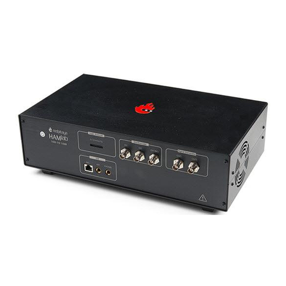
RX1 IN - direct feed to the first receiver pre-amp and attenuators. RX1 OUT - an output from the antenna feeding By default HAMlab 80-10 10W comes with loopback cable connected from RX1 IN to RX1 OUT. User can also use this two connectors to insert external filters or preamplifier. - Page 62 However, currently there is no support in HPSDR for a second TX output. 4.7.4. Power and Fuses The HAMlab 80-10 10W is designed to operate from a 13.8 volt nominal DC supply and required at least Danger This unit must only be operated with the electrical power described in this manual. NEVER CONNECT THE +13.8VDC POWER CONNECTOR DIRECTLY TO AN AC OUTLET.
- Page 63 Red Pitaya HAMlab Documentation Danger FUSE CURRENT RATING SHOULD NOT BE HIGHER THAN 3.15A AMPS! FAILURE TO PROPERLY USE THIS SAFETY DEVICE COULD RESULT IN DAMAGE TO YOUR RADIO, POWER SUPPLY, OR CREATE A FIRE RISK. 4.7.5. Chassis ground This is a thumbscrew for attaching an earth ground to the chassis of the radio. Grounding is the most important safety enhancement you can make to your shack.
- Page 64 Red Pitaya HAMlab Documentation the best for ground applications. Your station ground should be a common point where all grounds come together. You will likely be using a PC and a DC power source so be sure to ground these devices together as well.
- Page 65 Red Pitaya HAMlab Documentation 5. HAMlab 160-6 10W Specifications 5.1. SDR specifications 5.1.1. Highlights Architecture: direct sampling / internal high performance 14-bit A/D and D/A 125 Msps converters (no sound card required) Band coverage: All band receiver and 160-6m transmitter...
- Page 66 Red Pitaya HAMlab Documentation 5.2. Measurement instruments specifications 5.2.1. Oscilloscope Input channels Input channels connector Bandwidth 50 MHz Resolution 14 bit Memory depth 16384 Samples Max. Sampling Rate 125 MS/s Input range +/- 1 V or +/- 20 V Input coupling...
- Page 67 Red Pitaya HAMlab Documentation Note Acquired data is compressed therefore the size of data than can be captured depends on activity of signal on LA inputs. For I2C, SPI & UART signals 1MS is typical sample depth. All instrumentation applications are WEB based and don’t require the installation of any native software. Users can access them via a browser using their smartphone, tablet or a PC running any popular operating systems (MAC, Linux, Windows, Android and iOS).
- Page 68 / until the blue LED is turned off. 5.6.2. SDR 5.6.2.1. Microphone connector (RJ45) The HAMlab 80-10 10W front microphone connector (2) can support Kenwood KMC 30 electret microphone or compatible types. Front panel view microphone pinout...
- Page 69 5.6.2.3. Phones The HAMlab 80-10 10W supports a stereo headset with headphone ¼ inch TRS phone plug (4) . Mono or TS connector that grounds the “ring” portion of the connector should not be used! 5.6.2.4. Logic analyzer 0-7 are logic analyzer inputs.
- Page 70 RX1 IN - direct feed to the first receiver pre-amp and attenuators. RX1 OUT - an output from the antenna feeding By default HAMlab 80-10 10W comes with loopback cable connected from RX1 IN to RX1 OUT. User can also use this two connectors to insert external filters or preamplifier.
- Page 71 However, currently there is no support in HPSDR for a second TX output. 5.7.4. Power and Fuses The HAMlab 80-10 10W is designed to operate from a 13.8 volt nominal DC supply and required at least Danger This unit must only be operated with the electrical power described in this manual. NEVER CONNECT THE +13.8VDC POWER CONNECTOR DIRECTLY TO AN AC OUTLET.
- Page 72 Red Pitaya HAMlab Documentation Danger FUSE CURRENT RATING SHOULD NOT BE HIGHER THAN 3.15A AMPS! FAILURE TO PROPERLY USE THIS SAFETY DEVICE COULD RESULT IN DAMAGE TO YOUR RADIO, POWER SUPPLY, OR CREATE A FIRE RISK. 5.7.5. Chassis ground This is a thumbscrew for attaching an earth ground to the chassis of the radio. Grounding is the most important safety enhancement you can make to your shack.
- Page 73 PC in order to be able to use Phone, MIC and speaker connector for voice communication. Note USB connector is only available on HAMlab 80-10 10W model. For new models audio codec is used / audio is transferred over Ethernet.
-
Page 74: Troubleshoot
When trying to run PowerSDR please run SDR HPSDR web application before starting Power SDR. 6.3. Audio board not working (This troubleshoot is only for HAMlab 80-10 10W model) If audio there is no sound coming from your headphones or speaker connected to HAMlab while running... - Page 75 Red Pitaya HAMlab Documentation Set correnct Power SDR audio settings Make sure that HAMlab audio card was recognized by your Windows OS and driver is properly installed. Open control panel. Click on Hardware and Sound The manual is made on the site...
- Page 76 Red Pitaya HAMlab Documentation Check that audio card was recognized You can also make a simple test by playing some music with media player. The manual is made on the site https://trcvr.ru...
- Page 77 Red Pitaya HAMlab Documentation The manual is made on the site https://trcvr.ru...
- Page 78 Red Pitaya HAMlab Documentation 6.3.1. HAMlab doesn’t turn ON anymore Make sure your power supply is on and properly connected. Try to remove HAMlab cover and check the main fuse - if broken, try to replace it. 6.3.2. Cannot connect to HAMlab anymore Try to turn your HAMlab off and follow quick start procedure first.
Need help?
Do you have a question about the HAMlab 80-10 10W and is the answer not in the manual?
Questions and answers