
Related Manuals for Xavant STIMPOD NMS 410


Summary of Contents for Xavant STIMPOD NMS 410
- Page 1 NMS 410/450X Quantitative NMT Monitor Precision Nerve Locator Product Code: XT-45006-EN XM400-21A04 v10...
- Page 2 Warnings: • Read the entire User Manual before attempting to use the device. Xavant Technology PTY (LTD) • Use of cables or accessories other than those supplied with the STIMPOD may result Unit 102, The Tannery Industrial Park, 309 Derdepoort Rd in serious injury.
- Page 3 STIMPOD (NMS 410/450X) conforms to the following The Stimpod is designed to be compatible with a standard ECG electrode, however, standards: for high currents the use of a dedicated NMT electrode such as the Xavant XT45008 is recommended. • IEC 60601-1, IEC 60601-2-10 •...
- Page 4 Guidance and manufacturers declaration – electromagnetic emissions– for all equipment and systems The STIMPOD NMS 410/450X is intended for use in electromagnetic environment specified below. The customer or user of the STIMPOD NMS 410/450X should assure that it is used...
- Page 5 To assess the electromagnetic environment due to fixed RF transmitters, an electromagnetic site survey should be considered. If the measured field strength in the location in which the STIMPOD NMS 410/450X is used exceeds the applicable RF compliance level above, the STIMPOD NMS 410/450X should be...
- Page 6 STIMPOD NMS410/450X The STIMPOD NMS 410/450X is intended for use in an electromagnetic environment in which radiated RF disturbances are controlled. The customer or the user of the STIMPOD NMS 410/450X can help prevent electromagnetic interference by maintaining a minimum distance between portable and mobile RF communications equipment (transmitters) and the STIMPOD NMS 410/450X as recommended below, according to the maximum output power of the communications equipment.
-
Page 7: Table Of Contents
Contents Getting to know the STIMPOD (NMS 410/450X) 3.4) Train of Four Mode (TOF) 3.5) Double Burst Mode (DB) 1.1) Device Description 3.6) Post Tetanic Count Mode (PTC) 1.2) Accessories 3.7) Supra Maximal Current Mode (SMC) 1.3) Device Layout 3.8) Auto Mode 1.4) Screen Layout... -
Page 8: Getting To Know The Stimpod (Nms 410/450X)
The STIMPOD NMS 450X is quantitative Neuromuscular Transmission (NMT) Monitor which provides real-time quantitative feedback utilizing tri-axial accelerometry. The Stimpod NMS 410 as well as Stimpod NMS 450X is also a precision nerve locating tool used for localizing specific neural pathways. Localization of nerves by electrical stimulation involves connecting the nerve stimulator to a conducting needle through which local anaesthetics can be injected. -
Page 9: Accessories
• This cable is used to activate the NMT mode on the STIMPOD. • The red (anode) and black (cathode) connectors are designed to clip onto the Xavant NMT electrode (XT-45008) or onto a standard ECG electrode. • The accelerometer is designed to attach to the contracted appendage (in the case of the ulnar nerve, this will be the thumb). -
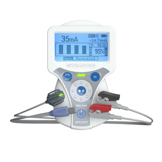
Page 10: Device Layout
1.3) Device Layout Cable Connector Insert the combined Nerve Mapping / Locating Multi Functional Clip Cable or the NMT cable to activate the relevant mode. Enter / Frequency Button Press to toggle between Frequencies. Press to Enter in setup menu. NM T Display 30.21... -
Page 11: Screen Layout
1.4) Screen Layout Linear mode Current Mode Nerve locating mode Non-Linear mode Nerve mapping mode NMT mode (NMS450X) Data Cable Speaker Volume Battery Status Current Setting Average current of actual stimulus Adjust using wheel Warning: Notifies the user of a discrepancy between current setting and average Facial Mode current of actual stimulus. -
Page 12: Warning Screens
1.5) Warning Screens Insert Cable Pause Insert Cable: Pause: This is the first prompt which the user will encounter as the unit is switched on, and This warning informs the user that the PAUSE button was pressed. signals that the unit is waiting for the cable to be inserted. The STIMPOD will pause all its activities and wait for the PAUSE button to be pressed again. - Page 13 EMI Warning EMI Warning: Component Error: The STIMPOD has detected a component failure. Please send the device back to the Warning shown when a high level of electromagnetic interference is detected. manufacturer for repair! Incorrect Electrode Placement Incorrect/Check electrode placement: Warning shown when SMC is unable to find a supramaximal current value.
-
Page 14: Open Circuit Detection
1.6) Open Circuit Detection 1.8) Symbols The Stimpod performs impedance measurements at regular intervals to detect whether the connection between the STIMPOD and the patient comprises a closed circuit. Closed Circuit Detected: • Stimulation will take place. • Stimulating sound will be heard (Single or multiple beeps depending on proximity Manufacturing Date Manufacturer Caution... -
Page 15: Nerve Locating/Mapping Mode (Nms 410/450X)
Nerve Locating/Mapping Mode (NMS 410/450X) Locating mode (LOC) This mode offers the user the means to do nerve mapping and locating without having to switch or unplug cables. Localisation of nerves by electrical stimulation involves connecting the nerve stimulator to a conducting, locating needle (not supplied) through which local anaesthetics can When inserting the Nerve Mapping / Locating Cable, the STIMPOD will default to the Nerve be administered. -
Page 16: A) Adjusting The Current In Loc Mode
When using the Nerve Locating / Mapping Cable Warning: Notifies the user of a discrepancy between current setting and average current of actual stimulus. If sound is enabled: STIMPOD will beep every time that a stimulus was delivered. The pitch of the sound will follow the current intensity level. -
Page 17: B) Adjusting The Current In Map Mode
Default Current and Pulse Width Range: NOTE: Because the 20 definable positions include both current and pulse width settings, As shown in table 1 in section 4.4 circle the Wheel to select the pulse width cannot be adjusted independently in this mode. This is indicated on the predetermined current and pulse width positions sequentially. -
Page 18: Adjusting The Pulse Width
2.2) Adjusting the Pulse Width 2.4) Adjusting the Twitch Frequency Options: 0.05ms, 0.1ms, 0.3ms, 0.5ms, 1ms Options: 1Hz, 2Hz, 5Hz Default: 0.05ms Default: 2Hz Press Menu/Pulse Width button to toggle between different Pulse Widths. Press Enter/Hz button to toggle between different stimulating frequencies. 2.3) Proximity Indicator This is only relevant for Locating Mode The proximity indicator notifies the user that the target charge range has been reached. -
Page 19: Neuromuscular Transmission(Nmt) Monitoring Mode (Nms 450X)
Neuromuscular Transmission(NMT) Monitoring Mode (NMS 450X) Monitoring Neuromuscular Blocking Agent involves stimulating a neural pathway which Targeted Nerve Affected Muscle Contracting Appendage facilitates the contraction of an appendage. Based on the relative strength of contraction Facial nerve (Zygomatic orbicularis oculi muscle Eye lid which is the result of a stimulus of specific intensity or waveform, it is possible to draw Branch) - Page 20 Refractory Period Delay The three modes: TOF, DB and PTC are subject to refractory period delays, providing a safety period which prevents the user from repeating stimulation while the nerve synapse is recovering from the effects of the previous stimulation. Immediately after stimulation in one of these modes, the countdown timer is activated and shown on the screen.
-
Page 21: Adjusting The Current
When using the NMT Mode (NMS 450X) Warning: Notifies the user of a discrepancy between current setting and average current of actual stimulus. If sound is enabled: STIMPOD will beep every time that a stimulus was delivered. The pitch of the sound will follow the current intensity level. -
Page 22: Train Of Four Mode (Tof)
3.4) Train of Four Mode (TOF) 3.5) Double Burst Mode (DB) The TOF stimulation comprises four, square waves with a pulse width of 200 microseconds, The DB stimulation comprises a burst of three square waves of 200microseconds pulse 500 milliseconds apart. width, 20 milliseconds apart, followed by another burst of three square waves, 750 milliseconds later. -
Page 23: Post Tetanic Count Mode (Ptc)
3.6) Post Tetanic Count (PTC) 3.7) Supra Maximal Current (SMC) Defaults: Note: When using facial electrodes, Facial Mode can be manually activated in the NMT Tetanus: 50Hz for 5 seconds menu. This will ensure that the current does not exceed 40mA. When activated, the facial Delay: 3 seconds mode icon will be visible (See 1.4). -
Page 24: Auto Mode
3.8) Auto Mode • Shallow: A TOF ratio less than 40%, but all pulses present. In Auto mode the device automatically changes the stimulation mode depending on • the depth of the block. When Auto mode is entered, the user must select whether the Moderate: A TOF count of 1 to 3. -
Page 25: Twitch Mode
3.9) Twitch (TWI) 3.10) Tetanus (TET) Defaults: Repeat at 2Hz Defaults: 50Hz (adjustable to 100Hz) Adjustable:1Hz, 2Hz and 5Hz The Tetanus stimulation comprises series of 200 microseconds square wave pulses The Twitch stimulation comprises a 200 microseconds square wave pulse. If the ‘Play/ repeated at a 50Hz or 100Hz repetition rate or frequency. -
Page 26: Setting Up Device Defaults
Setting up Device Defaults The setup menu allows the user to customize device parameters. Access the Setup Menu by pressing and holding the menu button. To exit the menu, the menu button may be pressed again. A block at the top of each menu indicates which menu is currently active. The menu is controlled using the menu button, the enter button and the Q-wheel. -
Page 27: Setup Menu
4.1) Setup Menu Language options: English (default), French, Italian, Dutch, Spanish, Portuguese, German, Swedish, Danish, Greek, Czech and Polish. The setup menu contains 3 sub menus, the contents of each will be covered in detail Volume options: Off, Low, Medium (default) and High. During operation, an icon on the in the next sections. -
Page 28: Nmt Settings
Timers: The timer items are changed in a two-step process, changing the number of minutes first and then the number of seconds. Use the wheel to navigate to the item which should be changed, then press the enter key to start editing. In scroll mode, the wheel can freely change the cursor position. -
Page 29: Locate Settings
Facial Mode: This item is toggled (On or Off ) by pressing the enter key. When on, the Current mode - Linear: The linear mode is called linear because one ‘ c lick’ on the wheel will resultant current determined by SMC will be limited to a 40mA maximum. correspond with one increment as set in the specific current range. - Page 30 These values can be viewed or changed in the Non-linear Settings menu. The charge value Current Pulse Width Charge Position for each or the twenty positions are displayed graphically, and the current and pulse width (mA) (ms) (µC) value of each position can be viewed by scrolling to that position using the wheel. 0.03 0.43 0.043...
-
Page 31: Technical Notes
Technical Notes 5.1) Performance Test _ _ _ Before operating and using the device a performance test must be carried out at the site of use. The performance test described below is in compliance with the German § 5 Insert Cable Insert Cable MPBetreibV directive. - Page 32 • 5.1.2) Combined Nerve Mapping/Nerve Locating Mode The LED should flash RED and no audible feedback should be heard. • Short-circuit the needle connector and the ECG connector. • The following screen should appear on the display. Insert the Nerve Mapping/Nerve Locating Cable. The following screen should appear on the display.
- Page 33 5.1.3) Neuromuscular Transmission Monitoring Mode (NMT Mode) (NMS450X only) • Insert the NMBA Cable. The following screen should appear on the display. Offener Stromkreis Open Circuit • Separate the red and black electrode connectors to cause an open circuit between erkannt Detected them.
-
Page 34: Specifications
Transport and Storage Atmospheric Pressure 50 – 106kPa 5.3) Cleaning and Disinfecting STIMPOD NMS 410/450 Cleaning: Soap and water, applied with a damp cloth is suitable to clean and disinfect the STIMPOD. It is imperative that no moisture penetrates the STIMPOD. -
Page 35: Products & Accessories
NMBA CABLE WITH ACCELEROMETER (3.5m) Product Code: XT-45025A POLYPROPYLENE CARRY CASE Product Code: XT-41002 ACCELEROMETER STRAP (Pack of 5) Product Code: XT-45007 NMBA ELECTRODE (Pack of 10) Product Code: XT-45008 INSTRUCTIONS FOR USE Product Code: XT-45006-EN (Refer to www.xavant.com for additional languages) - Page 36 Unit 102, The Tannery Industrial Park, 309 Derdepoort Rd Silverton, Pretoria, South Africa, 0184 Tel: +27 (0) 12 743 5959, Fax: +27 (0) 86 547 0026 (01)6009880396221(10)xxxxxxxxxx E-mail: support@xavant.com, Web: www.xavant.com...
Need help?
Do you have a question about the STIMPOD NMS 410 and is the answer not in the manual?
Questions and answers