Table of Contents
Advertisement
Quick Links
Advertisement
Table of Contents

Related Manuals for Maxxus CX 3.0


Summary of Contents for Maxxus CX 3.0
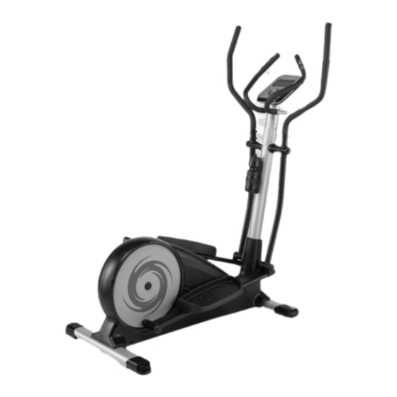
- Page 1 CX 3.0 Cross-Trainer...
-
Page 2: Table Of Contents
This publication may not be reproduced, stored in a retrieval system, or transmitted in whole or in part, in any form or by any means, electronic, mechanical, photocopying, recording, or otherwise without the prior written permission of Maxxus Group GmbH & Co. KG. -
Page 3: Safety Instructions
Safety Instructions Before you start exercising, be sure to read the entire user guide, especially the safety information, the maintenance & cleaning information and the training information. Take care too that everyone who uses this training device is also familiar with this infor- mation and observes it. -
Page 4: Overall View Of The Device
Overall View of the Device Pendulum Handle Cockpit Hand Pulse Sensor Bottle Holder Pendulum Tube Handlebar Shaft Pedal Transport Roller Pedal Tube Scope of Delivery A01 Base Frame A09 Fixed handlebar A07 Stand, front A08 Stand Rear C03/C12 Pedals, L/R Cockpit C17/C18 Pendulum Cover C24 Bottle Holder... -
Page 5: Assembly
Assembly Carefully unpack all the items delivered. Two people are required as some parts of your exercise equipment are bulky and heavy. Check that all fastening materials (screws, nuts, etc.) and the components are complete. Carry out each assembly step very carefully as damage or defects that have arisen due to assembly errors are not covered by the warranty under any circum- stances. - Page 6 Assembly Step 2: Remove the large polystyrene packaging block at the rear and lift the back end of the cross-trainer far enough up so you can push the block underneath it as a support. Loosen and remove the two 3/8” hex bolts (B11) and the two 3/8” washers (B10) that secure the transport lock to the rear mount of the cross-trainer.
- Page 7 Assembly Step 3.2: Screw the handlebar shaft (A02) to the base frame. Use six Allen screws M8x20 (B02) and six M8 curved washers (B01). CAUTION: Only tighten the screws slightly at first, then move the pedal tubes 2 to 3 turns to allow all com- ponents to align.
- Page 8 Assembly Step 5: Loosen and remove the three hexagon socket screws M8x20 (B31) and three curved washers M8 (B01) from the handlebar shaft (A02). Lead the cockpit cable (D04) protruding from the top of the handlebar shaft (A02), and end of the of the hand pulse measurement cable (D10) up through the handlebar (A09). Insert the handlebar (A09) into the upper opening of the handlebar shaft (A02).
-
Page 9: Assembly
Assembly Step 8: Assemble the Pendulum Tube Covers Attach two pendulum tube covers (C17-A / C18-B) to the joint between the left pendulum handle (A12) and the left pendulum tube (A03) using four self-tapping screws M5x16 (B22). Repeat with the right pendulum handle (A13) and pendulum tube (A04). Step 9: Assemble the Pivot Covers Attach two pivot covers (C29-B / C28-A) with five self-tapping screws M5x16 (B22) on the left pivot joint. -
Page 10: Floor Levelling
Floor Levelling Make sure your exercise equipment is always level. To be able to compensate for minor bumps and slopes, adjustable levelling feet are fitted on the right and left of the rear stand. In order to establish a level position of the device first turn all feet to the lowest position. -
Page 11: Care And Cleaning
Care and Cleaning CAUTION. Before you begin cleaning, maintenance and / or repair work, the training device must be completely discon- nected from the mains power. Disconnect the power plug from the wall outlet and then disconnect the power cord from the exerciser. The power cord may only be reconnected to the exerciser and the mains when all work has been fully completed and the device has been restored to its proper training position. -
Page 12: Cockpit
Cockpit USB port with charging function LCD display Storage compartment for Smartphone, Tablet PC Rotary control knob Recovery pulse measurement RESET key RECOVERY RESET Body fat analysis START / STOP key BODYFAT START/STOP MODE The cockpit constantly displays the current training values. TIME For a specified training time the computer counts the time down backwards to “00:00”. - Page 13 Cockpit Resistance level LOAD Displays the currently selected resistance level from level 1 to 16. Power WATT** Display of the output in watts (WATT). * Note on calorie measurement Calculation of energy consumption is done by means of a general formula. It is not possible to exactly match your individual energy consump- tion because this requires a large amount of personal data.
- Page 14 Cockpit Setting the User After the cockpit has been switched on the display shows “USER”. There are four user profiles U1 ~ U4 available. These are fixed storage locations where the user data is stored permanently. Selecting a User Profile Turn the rotary control knob to select the desired user profile and confirm your selection by pressing it.
- Page 15 Cockpit Calorie Consumption (CALORIES): The value in the “CALORIES” window flashes. If you want to specify the calorie consumption, then enter it by turning the rotary control right / left. You can set the calorie consumption from 10 to 9,990 calories. Confirm your selection by pressing the control.
- Page 16 Cockpit...
- Page 17 Cockpit Free training profile (USER) You can create a user training profile yourself and save it permanently here. Step 1: Program Selection Turn on the exerciser and select user U1-U4. The display shows MANUAL. Turn the rotary control “USER” and confirm your selection by pressing the control.
- Page 18 Cockpit Step 3: Specification of the training time The value in the “TIME” window flashes. Enter the exercise time by turning the rotary control clockwise / anti- clockwise. You can set the exercise time from 1:00 to 99:00 minutes in 1-minute increments. Step 4: Start Training Press the START / STOP key to start exercising.
- Page 19 Cockpit Recovery Heart Rate (RECOVERY) The recovery test measures how quickly you recover, i.e. how quickly and by how much your heart rate de- creases after training. After completing a workout, or after stopping the workout by pressing the Stop key, press the RECOVERY key and immediately place your hands on the hand pulse sensors.
-
Page 20: Cockpit
After successfully pairing the App with your training device, you can continue training by clicking on the arrow in the top right corner of the display. Please note that the MAXXUS Group GmbH & Co. KG is not the manufacturer of the iC + Training App and therefore are not responsible for their content or features. -
Page 21: Pulse & Heart Rate
Pulse & Heart Rate 100% of maximum heart rate of maximum heart rate of maximum heart rate of maximum heart rate Calculating your personal heart rate when training Calculate your personal heart rate when training as follows: 220 - Age = maximum heart rate This value represents your maximum heart rate and serves as a basis from which to calculate your personal training heart rate. -
Page 22: Pulse & Heart Rate
Heart Rate Measurement using a Chest Belt Many MAXXUS® training devices are already fitted with a receiver as standard. Using a chest belt (we recommend the exclusive use of an uncoded POLAR® chest strap) allows you to wire- lessly measure heart rate. The chest belt is as accessories available. -
Page 23: Training Recommendations
Training Recommendations Preparation Before Training Before you start training make sure that not only your training device is in perfect condition, your body must also be prepared for training. Therefore, if you have not done any endurance training for some time, you should con- sult your GP and undergo a fitness check-up. -
Page 24: Training Recommendations
Training Recommendations Hydration Adequate hydration is essential before and during exercise. During a training session of 30 minutes it is possible to lose up to 1 litre of liquid. To compensate for this fluid loss apple spritzer mixed in the ratio of one-third apple juice to two-thirds mineral water is ideal since it contains electrolytes and minerals to replace those that the body loses through sweat. -
Page 25: Technical Details
Technical Details Cockpit Display of: − Time − Speed − Distance − Revolutions per Minute − Calorie Consumption − Pulse (when using the hand sensors) − Level − Heart Rate (when using an optional chest belt) Technical details: Resistance system: Motorised permanent magnet Resistance adjustment: Computer controlled... -
Page 26: Exploded Drawing
Exploded Drawing... -
Page 27: Spare Parts List
Spare Parts List Part No. Description Part No. Description Main Frame M5 Self Tap Screw Upright Post Rivet Nut Dual Action Arm /L M6 Nylon Nut Dual Action Arm /R M10 Nut Foot Tube /L M20 Nut Foot Tube /R M8 Curve Washer Front Stabilizer Tube M8 Bolt... -
Page 28: Spare Parts List
Spare Parts List Part No. Description Part No. Description Bearing Bushing Magnetic Flywheel Washer 14 Cable Rubber Gasket Cable Pivot Cap -A Motor with Cable Pivot Cap -B Sensor Cable Front Cover /L AC Adaptor Front Cover /R AC Plug Cable Dome End Cap Hand Pulse Cable Bushing-Standard... -
Page 29: Recommended Accessories
All these extremely high-quality components ensure that all func- tional noises are very much reduced. Your MAXXUS® training device is one of the quietest products available in the fitness market. -
Page 30: Warranty
The warranty period for your training device starts on the date of purchase and applies solely to products which were purchased directly from the MAXXUS Group GmbH & Co KG or one of the MAXXUS Group GmbH & Co KG direct and authorised distribution partners. -
Page 31: Service Contract
I accept the General Terms and Conditions of MAXXUS® Group GmbH & Co. KG. I hereby instruct the company MAXXUS® Group GmbH & Co. KG to repair the above defects. In Warranty cases I will not be charged for the cost. The costs for repairs which are excluded from liability for defects in quality will be charged to me and must be settled my signature. - Page 32 Maxxus Group GmbH & Co. KG Zeppelinstr. 2 D-64331 Weiterstadt Germany E-Mail: info@maxxus.de www.maxxus.com...
Need help?
Do you have a question about the CX 3.0 and is the answer not in the manual?
Questions and answers