Table of Contents
Advertisement
Quick Links
Advertisement
Table of Contents

Subscribe to Our Youtube Channel
Related Manuals for Maxxus CX 6.1


Summary of Contents for Maxxus CX 6.1
- Page 1 CX 6.1 Cross Trainer...
- Page 2 This publication may not be reproduced, stored in a retrieval system, or transmitted in whole or in part, in any form or by any means, electronic, mechanical, photocopying, recording, or otherwise without the prior written permission of Maxxus Group GmbH & Co. KG.
-
Page 3: Safety Instructions
Safety Instructions Before you start exercising, be sure to read the entire user guide, especially the safety information, the maintenance & cleaning infor- mation and the training information. Take care too that everyone who uses this training device is also familiar with this information and observes it. -
Page 4: Scope Of Delivery
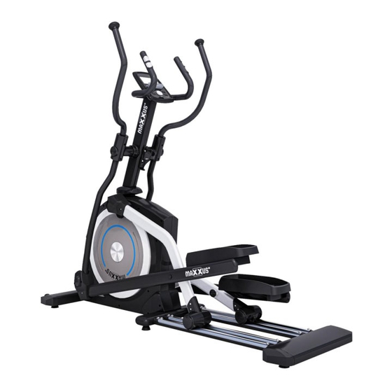
Overall View of the Device Pendulum Handle Cockpit Hand Pulse Sensors Handlebar Stem Bottle Holder Pendulum Tube Tread Stand with Transport Roller Slide Frame Pedal Tube Scope of Delivery Contents – Box 1 A13/A14 Base Frame Guide Tube, left Guide Tube, right Pendulum Handlebars Handlebar Stem Handlebars... - Page 5 Scope of Delivery Contents – Box 2 Slide Frame A05/A06 C07/C08 Pedal Tube, left / right Mains Adapter Handlebar Stem Cover C17/C18 Screw Cover, round Pendulum Tube Covers Guide Tube Covers Bottle Holder C28/C29 C32/C33 End Covers for Stand Roller Covers Cover plugs for Treads Assembly Carefully unpack all items from the delivery two people are required as some parts of your exercise equipment...
- Page 6 Assembly 1A Carriage bolt (B28) 2A Button head screw (B23) 3A Locknut (B29) 4A Curved washer (B30) M8x50 - 4 pieces M6x15 - 8 pieces M8 - 4 pieces M8x20x1.5T - 4 pieces 5A Pan head screw (B21) 6A Wrench/screwdriver 7A Allen screw (B19) 9A Allen key M5x16 - 22 pieces...
- Page 7 Assembly Step 3: Assemble the Handlebar Stem Connect the cable (D04) protruding from the handlebar shaft (A02) to the cable protruding from the base frame (A01). Attach the handlebar stem (A02) to the base frame with four hexagon head screws M8x20 (3B). CAUTION: Make sure that you do not crush or damage the cables (D04 / D05) when installing the handlebar stem.
- Page 8 Assembly Step 5.2: Assembling the Guide Tubes Slide the front mount of the right guide tube (A08) onto the small axle on the right disc drive of the base frame and place the rollers on each side of the right track on the slide frame. Fix the right guide tube (A08) with a hex bolt M8x16 (B32) and a washer 5/16”...
- Page 9 Assembly Step 6: Assembling the Guide Tube Covers Fix the guide tube cover (C21) with two pan head screws (5A) at the front of the right guide tube. Repeat this procedure with the left guide tube. Step 7: Assembling the Roller Covers Fix the two roller covers (C32, left/C33, right) using four pan head screws (5A) to the right guide tube just above the roller.
- Page 10 Assembly Step 8: Assembling the Fixed Handlebars Pass the cable (D04) protruding from the top of the handlebar shaft (A02) and the cables from the handlebars (A15) through the opening of plate of the cockpit bracket on the handlebars. Pull out the cable ends only as far as necessary to connect them to the cockpit. Then attach the fixed handle (A15) to the upper end of the handlebar shaft (A02) with two Allen screws M8x25 (7A).
- Page 11 Assembly Step 10: Assembling the Handlebar Stem Cover Attach the two handlebar covers (C07-left / C08-right) at the joint between the handlebar stem (A02) and the base frame using two pan head screws M5x16 (5A). Step 11: Assembling the Pendulum Tube Covers Attach two pendulum tube covers (C17-left / C18-right) at the joint between the right pendulum handle (A14) to the right pendulum tube (A04).
- Page 12 Assembly Step 12: Assembling the Treads Attach one of the two treads (C12) to the rear brackets on the left and right pedal tube (A05-left/A06-right). Fix each tread with four button head screws M6x15 (2A). Then press four cover plugs (C34) over the four screw holes on the top of the tread (C12).
-
Page 13: Levelling The Device
Levelling the Device Make sure your exercise equipment is always level. In order to compensate for minor bumps or slopes in the floor, adjustable feet are fitted on the right and left of the front and rear stands and on the sliding frame. To make sure the position of the device is level, first turn all feet to the lowest position (position A). -
Page 14: Safety Distance
For professional cleaning we recommend the MAXXUS® Degreaser Spray. Then dry the sliding tubes thoroughly and lubricate the top of the tubes with liquid silicone or MAXXUS® lubricant spray to form a thin layer. -
Page 15: Mains Connection
Mains Connection Mains Cable Insert the connector of the power cable supplied into the socket located on the front of the main housing. Then connect the mains cable to a power socket. WARNING This device is only to be connected to an earthed socket installed by a qualified electrician. Do not use a socket strip. - Page 16 Cockpit USB port with charging function LCD display Storage compartment for Smartphone, Tablet PC Control knob Recovery pulse measurement RESET key RECOVERY RESET BODYFAT START/STOP Body fat analysis START / STOP key MODE The cockpit constantly shows the current training values. TIME Specification of the training time.
- Page 17 Cockpit Keypad START/STOP Key START Function: – Start the selected training program or training profile – Activate the QUICK START function PAUSE Function: If the START / STOP key is pressed during training, the display of training values stops, and the pause mode is activated. This allows an interruption of training. To end the pause, press the START / STOP key again.
-
Page 18: Quick Start
Cockpit Quick-Start Turn on the training device and press the START / STOP key. The training time will start to run, and you can start training. At any time during training, you can adjust the resistance level from 1 to 16 by turning the control knob clockwise / anti-clockwise. - Page 19 Cockpit Training Profiles P1 – P12 In this type of training, the user can choose from twelve pre-programmed training profiles. The profile is not changeable; however, the user has the option of adjusting the intensity of the respective profile according to their current state of fitness.
- Page 20 Cockpit Free Training Profile (USER) Here you can create a training profile per user profile yourself and save it permanently. Step 1: Selecting a Program Turn on the exerciser. The upper part of the display flashes “M”. Select the program “U” by turning the control knob clockwise / anti-clockwise and confirm your selection by pressing it.
- Page 21 Cockpit Step 4: Setting the Training Time The value in the “TIME” window flashes. Enter the training time by turning the control knob clockwise / an- ti-clockwise. You can set the exercise time from 1:00 to 99:00 minutes in 1-minute increments. Step 5: Training Start Press the START / STOP key to start exercising.
- Page 22 Cockpit Recovery Heart Rate (RECOVERY) The recovery test measures how quickly you recover, i.e. how quickly and by how much your heart rate de- creases after training. After completing a workout, or after stopping the workout by pressing the Stop key, press the RECOVERY key and immediately place your hands on the hand pulse sensors.
- Page 23 After successfully pairing the App with your training device, you can continue training by clicking on the arrow in the top right corner of the display. Please note that the MAXXUS Group GmbH & Co. KG is not the manufacturer of the iC + Training App and therefore are not responsible for their content or features.
-
Page 24: Pulse & Heart Rate
Pulse & Heart Rate 100% of maximum heart rate of maximum heart rate of maximum heart rate of maximum heart rate Calculating your personal heart rate when training Calculate your personal heart rate when training as follows: 220 - Age = maximum heart rate This value represents your maximum heart rate and serves as a basis from which to calculate your personal training heart rate. - Page 25 Heart Rate Measurement using a Chest Belt Many MAXXUS® training devices are already fitted with a receiver as standard. Using a chest belt (we recommend the exclusive use of an uncoded POLAR® chest strap) allows you to wire- lessly measure heart rate. The chest belt is as accessories available.
-
Page 26: Training Recommendations
Training Recommendations Preparation Before Training Before you start training make sure that not only your training device is in perfect condition, your body must also be prepared for training. Therefore, if you have not done any endurance training for some time, you should con- sult your GP and undergo a fitness check-up. - Page 27 Training Recommendations Hydration Adequate hydration is essential before and during exercise. During a training session of 30 minutes it is possible to lose up to 1 litre of liquid. To compensate for this fluid loss apple spritzer mixed in the ratio of one-third apple juice to two-thirds mineral water is ideal since it contains electrolytes and minerals to replace those that the body loses through sweat.
-
Page 28: Technical Details
Technical Details Cockpit Display of: − Time − Speed − Distance − Wheel revolutions per Minute – RPM − Calorie Consumption − Pulse Rate (when using the hand sensors) − Power – WATT − Heart Rate (when using an optional chest belt) −... -
Page 29: Exploded Drawing
Exploded Drawing... -
Page 30: Spare Parts List
Spare Parts List Part No. Description Part No. Description Welded,Main frame M4 Sheet Metal Screw Welded,Upright Support Main Cover- Right Welded,Dual Action Left Main Cover- Left Welded,Dual Action Right Disc Cover Welded,Foot Pedal Tube Left End Cap for Stabilizer Bar Welded,Foot Pedal TubeR ight Height Adjuster Welded,Foot Tube Left... -
Page 31: Recommended Accessories
All these extremely high-quality components ensure that all func- tional noises are very much reduced. Your MAXXUS® training device is one of the quietest products available in the fitness market. - Page 32 Notes...
- Page 33 Notes...
-
Page 34: Terms And Conditions Of Warranty
The warranty period for your training device starts on the date of purchase and applies solely to products which were purchased directly from the MAXXUS Group GmbH & Co KG or one of the MAXXUS Group GmbH & Co KG direct and authorised distribution partners. -
Page 35: Service Contract
I accept the General Terms and Conditions of MAXXUS® Group GmbH & Co. KG. I hereby instruct the company MAXXUS® Group GmbH & Co. KG to repair the above defects. In Warranty cases I will not be charged for the cost. The costs for repairs which are excluded from liability for defects in quality will be charged to me and must be settled immediately. - Page 36 Maxxus Group GmbH & Co. KG Maxxus Group GmbH & Co. KG Zeppelinstr. 2 Zeppelinstr. 2 D-64331 Weiterstadt D-64331 Weiterstadt Germany Germany E-Mail: info@maxxus.com E-Mail: info@maxxus.com www.maxxus.com www.maxxus.com...
Need help?
Do you have a question about the CX 6.1 and is the answer not in the manual?
Questions and answers