Table of Contents
Advertisement
Quick Links
Advertisement
Table of Contents

Subscribe to Our Youtube Channel
Related Manuals for Maxxus Multipress 10.1


Summary of Contents for Maxxus Multipress 10.1
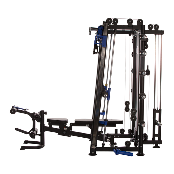
- Page 1 Multipress 10.1 Installation Manual...
-
Page 2: Table Of Contents
Maxxus Group GmbH & Co. KG. Errors, colour and technical modification subject to change, reproduction as well as electronic duplication only with written permission of Maxxus Group GmbH & Co. KG. -
Page 3: Safety Intructions
Any manipulation of or interference with the device can cause damage to the device and be a danger to people. If you have any questions or queries contact your specialist dealer or the MAXXUS Service Team and they will be pleased... -
Page 4: Scope Of Delivery
Scope of Delivery – Multipress... - Page 5 Scope of Delivery – Multipress...
-
Page 6: Scope Of Delivery
Scope of Delivery – Multipress Traction Cable (39) - Length 4.430 mm Traction Cable (42) - Length 1.860 mm 2x Traction Cable (47) - Length 2.380 mm 2x Traction Cable (58) - Length 3.580 mm Traction Cable (59) - Length 10.690 mm Note: When assembling the rollers (38) only tighten the screws so far that they are turned into the nut. -
Page 7: Fixing Materials - Multipress
Fixing Materials – Multipress... - Page 8 Fixing Materials – Multipress...
-
Page 9: Fixing Materials - Multipress
Fixing Materials – Multipress... -
Page 10: Parts List - Multipress
Parts List – Multipress Part Description Part Description T Frame, base Draw Bar, short Side Frame, left Chain with Carabiner, long Side Frame, right Roller Ø95xØ1.5x24.4 Pull-up, cross-beam Traction Cable - Length 4.430mm Roller retainer, left Double Roller Roller retainer, right Hex. -
Page 11: Parts List - Multipress
Parts List – Multipress Part Description Hex. Head Screw M10x75 Hook Carabiner Hook Pull Bar, long Pull Grip Dumbbell Bar Holder, fixed Dumbbell Bar Holder, moving Shelf, long Mounting for Leg Stabiliser Leg Holster w. Curved Cushion Threaded Spring Clip Grip Locking Pin Ø10x100 Roller Guide Foot, rear... - Page 12 Assembly – Multipress Assembly Step 1: Fix the traction weights (49) with a washer Ø12 (12) to each threaded end of the traction cable (47). Then put a traction weight (49) in the rear pipe on the left and right-side frame (2-left/3-right) – see here the circle section diagram. Now, mount the two rollers (38), each with a hexagonal head screw M10x50 (46), two washers Ø10 (9), a cable guide (48) and a safety nut M10 (10) in the two upper roller holders on the left-hand side frame (2).
- Page 13 Assembly – Multipress Assembly Step 2 Connect the left-hand side frame (2) the right-hand side frame (3) and the rear side frames to the base frame (1) at the bottom. For this use on each side; 2 hexagonal head screws M10x100 (8), four washers Ø10 (9), two safety nuts M10 (10) and a curved mounting plate (7).
- Page 14 Assembly – Multipress Assembly Step 3 First mount the roller guide (85) to the rear foot (86) using two hexagonal head screws M10x50 (46), four washers Ø10 and two safety nuts M10 (10) see here the circled segment diagram. Then fix rear foot (86) onto base frame (1) using two hexagonal head screws M12x30 (60), two spring plates Ø12 and two washers Ø12 (12).
- Page 15 Assembly – Multipress Assembly Step 4: Hook-in the dumbbell bar (16) with the holding hooks to the left and right-hand side frames. Slide the basic pipe for the barbell bar (90) through the grip bar with hooks (16). Tipp: First lubricate or fat the surface of the basic pipe (90) with some multi-function fat or with a silicon spray. Assembly of the left Guide Pipe (17) Slide the following parts onto the guide pipe (see circled segment diagram): - Guide element (23) –...
- Page 16 Assembly – Multipress Assembly Step 4.1: Slide a weight sleeve (18) on the right and left ends of the dumbbell bar (16). Fix each of these with an end piece, round (20), a washer Ø12 (12) and a hexagonal head screw M12x25 (19).
- Page 17 Assembly – Multipress Assembly Step 5: Fix the loop on the end traction cable (47), which you already assembled in Step 1, using one of each of the following; hex- agonal head screw M10x25 (33), two washers Ø10 (9) and a safety nut M10 (10) to the left and right-hand guide elements on the dumbbell bar –...
- Page 18 Assembly – Multipress Assembly Step 6 Place the rear guide pipes (29) in the mountings on the weight slide (30). Make sure that both dumbbell plate mountings on the weight slide are pointing upwards. Slide on the two round rubber dampers (31) from below onto the guide pipes (29). Then place the guide pipes in the drill holes in the lower T-frame using one screw M10x20 (34) and a washer Ø10 (9) on each side.
- Page 19 Assembly – Multipress Assembly Step 7 Connect the end of the traction cable (39) with the thread connection on the weight slide. Feed the traction cable (39) up and over single rollers (1) and (2) and assemble rollers (1) and (2) onto the T-frame. Then feed traction cable (39) over the upper rollers on double roller (40) and then over roller (4) on the T-frame.
- Page 20 Assembly – Multipress NOTES: Assembly of the Traction Cable: To feed the traction cable through the rollers or through the hole in foot plate, undo and remove the screw and nut at the ball end of the cable. Then remove the U-bracket and the ball and metal cup plate. Replace these parts on the end of the traction cable once you have finished assembling it.
- Page 21 Assembly – Multipress Assembly Step 8 Fix the single roller holder (44) and washer Ø10 (12) onto the thread on the end of the traction cable (42). Then feed the other looped end of the traction cable (42) over the lower roller of double roller (40) mounted in Step 4. Now hang one of the carabiner hooks on the chain onto the looped end of the traction cable and the second carabiner on chain (45) to the loop on the lower T-frame.
- Page 22 Assembly – Multipress...
- Page 23 Assembly – Multipress Assembly Step 9 Fix the lower left roller holder (51) with 2 hexagonal head screws M12x70, four washers Ø12 and two safety nuts M12 (13) to the left-hand side frame. Repeat this procedure on the right-hand side. Roller holders have been correctly assembled if the roller on the right-hand roller holder is turning slightly to the right and the left-hand roller is turning slightly to the left.
- Page 24 Assembly – Multipress Assembly Step 10 Place the left-hand guide frame with double roller (54) onto one of the guide pipes (56). Make sure that it is correctly aligned. Then fix guide frame (54) with a locking pin (57) on the guide pipe (56). Now fix the square guide pipe (56) to the top and bottom of the left-hand side frame.
- Page 25 Assembly – Multipress Assembly Step 11 Fix the end of the traction cable (58) (threaded retainer – not the looped end!) using a safety nut M10 (10) and a washer Ø10 (9) to the left-hand guide frame with double roller (54). Feed through the looped end of the traction cable (58) upwards through the hole in the connecting piece between the left-hand guide pipe and the left-hand side frame.
- Page 26 Assembly – Multipress Firmly tighten up the socket head screws again before assembling traction cable (58)
- Page 27 Assembly – Multipress Assembly Step 12 Mount the 10 rollers (38) on the appropriate roller holders using a hexagonal head screw M10x45 (41), two washers Ø10 and a safety nut M10 (10) – see diagram and description on the next page. Loosen the ball bracket at the end of traction cable (59) –...
- Page 28 Assembly – Multipress Position to mount the rollers in: Note: I, K, K L, M, N, O, P, Q M and N are to be attached to the single roller holder (44) already assembled in Step 4. Roller sequence in the traction cable assembly (59): Guide frame, right (55) - H - I - J - K - L - N - O- P - Q - R - T –...
- Page 29 Assembly – Multipress NOTES: Assembly of the Traction Cable: To feed the traction cable through the rollers or through the hole in foot plate, undo and remove the screw and nut at the ball end of the cable. Then remove the U-bracket and the ball and metal cup plate. Replace these parts on the end of the traction cable once you have finished assembling it.
- Page 30 Assembly – Multipress Assembly Step 13 Fix four barbell sleeves (61) onto the appropriate mounts on the right and left-hand side frames. To do this use for each barbell sleeve (61); 2 hexagonal head screws M12x30 (60), four washers Ø12 (12) and two safety nuts M12 (13). Place one spring clip (62) on each barbell sleeve (61).
- Page 31 Assembly – Multipress Assembly Step 14 Attach cover plate (63) to the top and bottom T-cross bar. For each connection upper and lower 2 hexagonal head screws M8x20 (64), two spring plates Ø8 (65) and two washers Ø8 (66). Please ensure that cover plate (63) is assembled behind footplate (32), assembled in Assembly Step 3, on the lower T-cross bar...
- Page 32 Assembly – Multipress Assembly Step 15 Fix the movable dumbbell bar bracket (78) to the right-hand side frame. For this use a hexagonal head screw (M10x20 (34) and a washer Ø30xØ10,5 (79) Then fix the dumbbell bar bracket (77) to the left-hand side frame. For this use two hexagonal screws M10x70 (53), four washers Ø10 (9) and two safety nuts M10 (10).
- Page 33 Assembly – Multipress Fitting the Accessories Leg Stabiliser Before using this accessory, fix the leg holster to the curved cushion (82) and the threaded spring-clip grip (83) onto the leg stabiliser mounting (81). Place then the complete unit to the front of the right- hand side frame and fix it with locking pin (84)
-
Page 34: Assembly - Multipress
Be sure to clean all six chrome guide pipes before using the device for the first time. We recommend MAXXUS® degreaser spray for cleaning and MAXXUS® lubricant spray for lubrication of tubes and pipes. Never use Teflon based lubricants to lubricate the pipes and bars. -
Page 35: Assembly - Training Bench
Assembly – Training Bench... - Page 36 Assembly – Training Bench Assembly Step 1 Fix the rear floor bar (2) to base bar (3) using two hexagonal head screws M10x75 (6), four washers Ø10 (33), two safety nuts M10 (52) and straight retaining plate (7). Place standpipe (51) onto front floor bar (1) and fix it with two hexagonal screws M12x75 (55), four washers Ø12 (54) and two safety nuts (53).
- Page 37 Assembly – Training Bench Assembly Step 3 Now fix the base frame (18) to the front mount of the sliding carriage (16). For this use two hexagonal head screws M8x20 (19), two washers Ø8 (32) and a distance tube (30). Assembly Step 4 Fix swivel bracket (35) using two hexagonal head screws M10x20 (39), two washers Ø10 (33) and distance tube (42) to the mount on standpipe (51).
- Page 38 Assembly – Training Bench Assembly Step 5 Place the three cross pipes (37) – into the swivel bracket and base – as shown in the Diagram. Push a cover plate (large opening) (48) on to both ends of each cross pipe (37) with the opening facing outwards (see Diagram). Slide on a round cushion (47) on the right and left ends of each cross pipe (37) and fix them with a cover place (small open- ing) (49) and a hexagonal head screw M8x25 (50).
-
Page 39: Assembly - Training Bench
Assembly – Training Bench Assembly Step 7 Attach back rest cushion (29) to the back-rest support tube (17) using four hexagonal screws M8x20 (19) and four washers Ø8 (32) Assembly Step 8 Attach the seat cushion (31) to the sliding carriage (16) using four hexagonal screws M8x20 (19) and four washers Ø8 (32). - Page 40 Assembly – Training Bench...
- Page 41 Assembly – Training Bench Part Description Type Quantity Base Bar, front Base Bar, rear Base Bar Mounting Plate, bent T3,0x59x140 Hexagonal Head Screw M10x100 Hexagonal Head Screw M10x75 Mounting Plate, straight T4,0x50x140mm Grip Screw with Locking Pin M18x1.5mm Sliding Carriage Support Tube for Back-Rest Base Frame for Seat Cushion Hexagonal Head Screw...
-
Page 42: Care, Cleaning & Maintenance
Alternatively, you can use the MAXXUS® degreaser spray (optionally available). After this, dry the guide pipes off thoroughly and lubricate them with MAXXUS®... -
Page 43: Training Recommendations
Training Recommendations Preparation Before Training Before you start training make sure that not only your training device is in perfect condition, your body must also be pre- pared for training. Therefore, if you have not done any endurance training for some time, you should consult your GP and undergo a fitness check-up. -
Page 44: Training Recommendations
Training Recommendations Intake of Liquids The intake of sufficient liquids before and during training is vital. During a 60-minute training session it is possible to lose up to 0.5 litres of liquid. To compensate for this loss, you can drink a mix of one third apple juice to two thirds water to replace all electrolytes and min- erals which your body loses through sweat. -
Page 45: Warranty
The warranty period for your training device starts on the date of purchase and applies solely to products which were pur- chased directly from the Maxxus Group GmbH & Co. KG, or one of the Maxxus Group GmbH & Co. KG direct and author- ised distribution partners. -
Page 46: Notes
Notes... - Page 47 I acknowledge the General Business Terms and Conditions of Maxxus Group GmbH & Co. KG. I hereby instruct the company Maxxus Group GmbH & Co. KG to repair the above-mentioned fault. In Warranty cases I will not be charged for the costs. The costs for repairs which are excluded from liability for defects in quality will be charged to me and must be settled immediately.
- Page 48 Maxxus Group GmbH & Co. KG Zeppelinstr. 2 D-64331 Weiterstadt Germany E-Mail: info@maxxus.de www.maxxus.de...
Need help?
Do you have a question about the Multipress 10.1 and is the answer not in the manual?
Questions and answers