Advertisement
Quick Links
Advertisement

Related Manuals for Maxxus 7.8


Summary of Contents for Maxxus 7.8
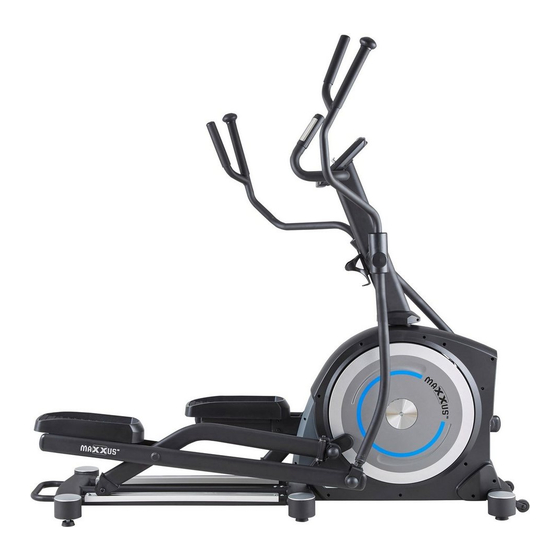
- Page 1 MAXXUS 7.8 Cross Trainer...
- Page 2 Maxxus Group GmbH & Co. KG. Duplication, including electronic form, is only permitted with prior written permission directly from MAXXUS Group GmbH & Co. KG. Errors, colour and technical modification are subject to change...
- Page 3 Safety Instructions Before you start exercising, be sure to read the entire user guide, especially the safety information, the maintenance & cleaning infor- mation and the training information. Take care too that everyone who uses this training device is also familiar with this information and observes it.
- Page 4 Scope of Delivery Box 1 Base Frame - 1 Piece Slide Frame - 1 Piece Fixed Handle Bar - 1 Computer - 1 Piece Handle, left Piece - 1 Piece Handle, right Pedals - 2 Pieces Lubricant - 1 Piece - 1 Piece Box 2 A05/A07...
-
Page 5: Table Of Contents
Fixing Materials & Tools B33 (2) B41 (3) B32 (4) B30 (6) B28 (7) Washer Hexagon Socket Hexagon Head Screw Curved Washer Carriage Bolt Ø5/16”x30x2.0T - 4 Screw M8x16 mm - 4 Piece M8x20x1.5T - 4 Piece M8x50 mm - 4 Piece Piece M8x25 mm - 2 Piece B40 (8) - Page 6 Assembly Step 1: Assembly of the Slide Frame Put both round caps in the holes of the base frame (A01) and the slide frame (A12) - Fig 1.1 and 1.2. Undo and remove the six pre-assembled screws (B13) and curved washers (B30) from the base frame mount (A01) – Fig 2.
-
Page 7: B44
Assembly Step 2: Assembly of the Handle Bar Shaft Connect the cable (D04) protruding out of the handle bar shaft (A02) with the cable (D05) protruding out of the mount of the base frame. Then fix the handle bar shaft (A02) with the four hexagon head screws (B44) to the base frame.. - Page 8 Assembly Step 4: Greasing the Axels Before you continue with assembly, thoroughly grease the four axels shown in the diagram with the lubricator supplied at delivery. Step 5: Assembly of the Pendulum Tubes, Pedal Arms and Guide Tubes Step 5.1: Undo and remove the pre-assembled screw (B24), washer (B33) and nut (B29) from the lower mount on the right pendulum tube (A04).
-
Page 9: B32
Assembly Step 5.2: Now place the right pendulum tube (A04) onto the previously greased right axle of the handle bar shaft (A02). Then fix the pendulum tube (A04) with a screw (B32) and a washer (B33). Step 5.3: Slide the front mount of the right guide tube (A08) onto the small axle (A11) of the right drive plate on the base frame and place the roller (C20) onto the right track (F01) of the slide frame (A12). -
Page 10: B29
Assembly Step 6: Assembly of the Fixed Handle Bar Feed the cable protruding out of the top of the handle bar shaft (A02) and the cable from the fixed handle bar (A16) through the opening in the cockpit holder plate – see circled part diagram. Only pull out the cable ends far enough to connect them with the cockpit. - Page 11 Assembly Step 8: Assembly of the Pendulum Tube Covers Fix both pendulum tube covers (C17- left/C18-right) to the joint between the right pendulum handle (A14) and the right pendulum tube (A04) To do this use four tapping screws (B40). Repeat this procedure with the left pendulum handle (A13) and the left pendulum tube (A03).
- Page 12 Assembly Etape 11 : Assemblage du cockpit Loosen the four pre-assembled round head screws (B17) on the back of the cockpit (D02). Connect the cable protruding from out of the cockpit (D02) with the cables coming out of the fixed handle bar (A16). Please be aware that the two cables for the hand pulse sensors have identical connections.
- Page 13 Transport, Location & Storage Transport In order to transport your training device simply and safely, the front stand is equipped with transport rollers. To transport the exerciser, stand at the rear end of the glide frame and grasp the rear cross tube with both hands. Now tip the training device upwards until the main weight of the training device rests on the transport rollers.
- Page 14 For professional cleaning we recommend the MAXXUS® Degreaser Spray. Then dry the sliding tubes thoroughly and lubricate the top of the tubes with liquid silicone or MAXXUS® lubricant spray to form a thin layer.
- Page 15 Mains Connection Mains Cable Plug the mains cable on the supplied mains adapter into the socket located on the front of the main body. Then plug the mains cable into a power socket. CAUTION The device may only be connected to an earthed socket that has been professionally installed. Do not use mul- tiple sockets to connect the exerciser.
- Page 16 Cockpit USB port with charging function LCD display Storage compartment for Smartphone, Tablet PC Control knob RESET key Recovery pulse measurement START / STOP key Body fat analysis The cockpit constantly shows the current training values. TIME Specification of the training time. For a given training session, the computer counts down the time to “00:00.” The training time can be set from “01:00”...
- Page 17 Cockpit Keypad START/STOP Key START Function: – Start the selected training program or training profile – Activate the QUICK START function PAUSE Function: If the START / STOP key is pressed during training, the display of training values stops, and the pause mode is activated. This allows an interruption of training. To end the pause, press the START / STOP key again.
- Page 18 Cockpit Quick-Start Turn on the training device and press the START / STOP key. The training time will start to run, and you can start training. At any time during training, you can adjust the resistance level from 1 to 16 by turning the control knob clockwise / an- ti-clockwise.
- Page 19 Cockpit Training Profiles P1 – P12 In this type of training, the user can choose from twelve pre-programmed training profiles. The profile is not changeable; however, the user has the option of adjusting the intensity of the respective profile according to their current state of fitness. Step 1: Program Selection Turn on the exerciser.
- Page 20 Cockpit Free Training Profile (USER) Here you can create a training profile per user profile yourself and save it permanently. Step 1: Selecting a Program Turn on the exerciser. The upper part of the display flashes “M”. Select the program “U” by turning the control knob clock- wise / anti-clockwise and confirm your selection by pressing it.
- Page 21 Cockpit Step 4: Setting the Training Time The value in the “TIME” window flashes. Enter the training time by turning the control knob clockwise / anti-clockwise. You can set the exercise time from 1:00 to 99:00 minutes in 1-minute increments. Step 5: Training Start Press the START / STOP key to start exercising.
- Page 22 Cockpit Recovery Heart Rate (RECOVERY) The recovery test measures how quickly you recover, i.e. how quickly and by how much your heart rate decreases after training. After completing a workout, or after stopping the workout by pressing the Stop key, press the RECOVERY key and immedi- ately place your hands on the hand pulse sensors.
- Page 23 After successfully pairing the App with your training device, you can continue training by clicking on the arrow in the top right corner of the display. Please note that the MAXXUS Group GmbH & Co. KG is not the manufacturer of the iC + Training App and therefore are not responsible for their content or features.
- Page 24 Pulse & Heart Rate 100% of maximum heart rate of maximum heart rate of maximum heart rate of maximum heart rate Âge Calculating your personal heart rate when training Calculate your personal heart rate when training as follows: 220 - Age = maximum heart rate This value represents your maximum heart rate and serves as a basis from which to calculate your personal training heart rate.
- Page 25 Heart Rate Measurement using a Chest Belt Many MAXXUS® training devices are already fitted with a receiver as standard. Using a chest belt (we recommend the exclusive use of an uncoded POLAR® chest strap) allows you to wire- lessly measure heart rate. The chest belt is as accessories available.
- Page 26 Training Recommendations Preparation Before Training Before you start training make sure that not only your training device is in perfect condition, your body must also be pre- pared for training. Therefore, if you have not done any endurance training for some time, you should consult your GP and undergo a fitness check-up.
- Page 27 Training Recommendations Hydration Adequate hydration is essential before and during exercise. During a training session of 30 minutes it is possible to lose up to 1 litre of liquid. To compensate for this fluid loss apple spritzer mixed in the ratio of one-third apple juice to two-thirds min- eral water is ideal since it contains electrolytes and minerals to replace those that the body loses through sweat.
- Page 28 Technical Details Cockpit Display of: − Time − Speed − Distance − Wheel revolutions per Minute – RPM − Calorie Consumption* − Pulse Rate (when using the hand sensors) − Power – WATT** − Heart Rate (when using an optional chest belt) −...
- Page 29 Disposal European Disposal Regulations 2012/19/EU Do not dispose your training device in the normal household rubbish. Dispose the device at a communal waste disposal facility or at a registered waste disposal company. Observe current regulations which apply accordingly. If in doubt seek advice from your local government office or county council as to where you can dispose of the device properly and in an environmentally sound manner.
- Page 30 Exploded Drawings...
- Page 31 Spare Parts List Part Description Part Description Welded, Main Frame Screw M6 Welded, Upright Post Bolt M8 Welded, Handrail Arm /L Nut M8 Welded, Handrail Arm /R Nylon Nut M10 Welded, Foot Pedal Tube /L C-ring Ø17 Welded, Foot Pedal Tube /R Carriage Bolt M8 Welded, Rotate Tube /L Nylon Nut M8...
- Page 32 Spare Parts List Part Description Part Description Handrail Arm Decorative Cover-A Upper Cable Handrail Arm Decorative Cover-B Lower Cable Pulley Motor Roller Sensor Cable End Cap AC Adaptor 9V/1.000mA Washer Ø17 AC Plug Cable Upright Post Spacer Hand Pulse Cable 1Set Crank Cover Motor Tension Cable...
- Page 33 All these extremely high-quality components ensure that all functional noises are very much reduced. Your MAXXUS® training device is one of the quietest products available in the fitness market. However, it is possible and normal that slight mechanical noises are noticeable during train- ing.
- Page 34 MAXXUS® Special Foam Cleaner – Use for regular cleaning of your training device. Plastic covers and metal frames can be easily cleaned and perfectly maintained with MAXXUS ® Special Foam Cleaner. It is also suitable for cleaning pulse belts and other training accessories.
- Page 35 Notes...
- Page 36 Notes...
- Page 37 Notes...
- Page 38 The warranty period for your training device starts on the date of purchase and applies solely to products which were purchased directly from the MAXXUS Group GmbH & Co KG or one of the MAXXUS Group GmbH & Co KG direct and authorised distribution partners.
- Page 39 I accept the General Terms and Conditions of MAXXUS® Group GmbH & Co. KG. I hereby instruct the company MAXXUS® Group GmbH & Co. KG to repair the above defects. In Warranty cases I will not be charged for the cost. The costs for repairs which are excluded from liability for defects in quality will be charged to me and must be settled immediately.
- Page 40 Maxxus Group GmbH & Co. KG Zeppelinstr. 2 D-64331 Weiterstadt Allemagne E-Mail: info@maxxus.de www.maxxus.de...
Need help?
Do you have a question about the 7.8 and is the answer not in the manual?
Questions and answers