
Related Manuals for Mandik FDMC Series


Summary of Contents for Mandik FDMC Series
- Page 2 These technical specifications state a row of manufactured sizes and models of fire dampers (further only dampers) FDMC. It is valid for production, designing, ordering, delivery, assembly and operation. 1. Description......................... 2. Design..........................3. Dimensions, weights......................4. Placement and Assembly....................5.
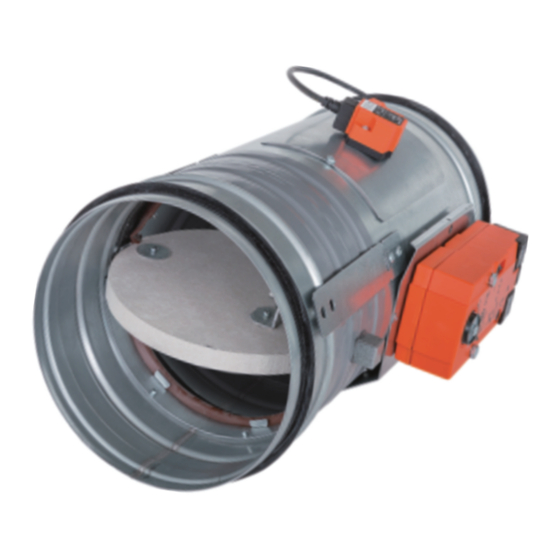
- Page 3 Fire dampers are shutters in ducts of air-conditioning devices that prevent spreading the fire and combustion products from one fire segment to the other one by means of closing the duct in the points of fire separating constructions. Damper blade automatically closes air duct using an actuating mechanism back spring. The back spring of the actuating mechanism is started when the thermoelectrical starting mechanism BAT is activated, when a reset button on BAT is pushed or when a power supply of the actuating mechanism is stopped.
- Page 4 Operation of the dampers does not depend on the direction of air circulation. The dampers can be located in an arbitrary position. Dampers are suitable for systems without abrasive, chemical and adhesive particles. Dampers are designed for macroclimatic areas with mild climate according to EN 60 721-3-3. Temperature in the place of installation is permitted to range from - 20°C to + 50°C.
- Page 5 Weight and effective area 0,0036 0,0068 0,0092 0,0109 0,0129 0,0172 0,0222 0,0293 0,0374 0,0484 41,5 0,0630 0,0793 61,5 0,0821 0,1065 The Blade overlaps For fire damper the open damper blade overlaps the damper body from dimension 250 by the “a” value. These values are specified in the Tab. 3.2.1 Value has to be respected when projecting related air-conditioning piping.
- Page 6 Fire dampers are suitable for installation in arbitrary position in vertical and horizontal passages of fire separating constructions. Damper assembly procedures must be done so as all load transfer from the fire separating constructions to the damper body is absolutely excluded. Back-to-back air-conditioning piping must be hung or supported so as all load transfer from the back-to-back piping to the damper is absolutely excluded.
- Page 7 Examples of fire damper installing The fire damper can be installed into a solid wall construction made e.g. of normal concrete/masonry, porous concrete with minimum thickness 100 mm or into solid ceiling construction made e.g. of normal concrete/porous concrete with minimum thickness 150 mm. Recommended installation openings are specified in Fig.
- Page 8 Appropriate isolation and installation materials for fire resistance EIS 60 should be used. Producer of these materials is random (Isover, Protecta, Rockwool, PAROC etc.) Used materials must be approved and have min. the same fire resistance as required for Fire Damper - EIS 60, or higher. Position: Fire damper FDMC 3 Fire protection mastic min.
- Page 9 Position: Fire damper FDMC Mortar or gypsum with min. density 800 kg/m or another approved fire sealing system for damper installation Position: Fire damper FDMC 3 Fire protection mastic min. thickness 1 mm: Stuffing box (mineral stone wool min. density 140 kg/m³) Protecta FR Akryl or Isover U Protect BSF or or another approved fire sealing system for damper installation other approved...
- Page 10 Position: Fire damper FDMC 4 Duct Stuffing box (mineral stone wool min. density 140 kg/m³) 5 Installation shaft - inner space or another approved fire sealing system for damper installation Fire protection mastic min. thickness 1 mm: Protecta FR Akryl or Isover U Protect BSF or other approved Park Allé...
- Page 11 859 1002 1145 1288 1431 10,9 13,1 15,3 17,5 19,6 21,8 10,9 12,2 13,6 21,6 29,1 35,0 39,7 43,7 47,2 50,3 53,0 15,1 22,6 28,4 33,2 37,2 40,7 43,7 46,5 148,0 26,3 41,0 59,1 80,4 105,1 133,0 164,2 10,3 14,0 18,3 23,2 28,6 884 1060 1237 1414 1590 1767 10,8 12,6 14,4...
- Page 12 Actuating mechanism S1 S2 <5° <80° Damper bodies are supplied in the design made of galvanized plate without any other surface finish. Damper blades are made of fire resistant asbestos free boards made of mineral fibres. Fasteners is galvanized. The appliance is constructed and and preset by the manufacturer, its operation is dependent on proper installation and adjustment.
- Page 13 Dampers are transported by box freight vehicles without direct weather impact, there must not occur any sharp shocks and ambient temperature must not exceed +40°C. Dampers must be protected against mechanic damages when transported and manipulated. During transportation, the damper blade must be in the "CLOSED" position. Dampers are stored indoor in environment without any aggressive vapours, gases or dust.
- Page 14 technical specifications size type Park Allé 366, DK-2605 Brondby Telefon 70 20 19 11; E-mail:oeland@oeland.dk...
- Page 15 MANDÍK, a.s. Dobříšská 550 26724 Hostomice Czech Republic Tel.: +420 311 706 706 E-Mail: mandik@mandik.cz www.mandik.com The producer reserves the right for innovations of the product. For actual product information see www.mandik.com Park Allé 366, DK-2605 Brondby Telefon 70 20 19 11; E-mail:oeland@oeland.dk...
Need help?
Do you have a question about the FDMC Series and is the answer not in the manual?
Questions and answers