Mandik FDMC Manual
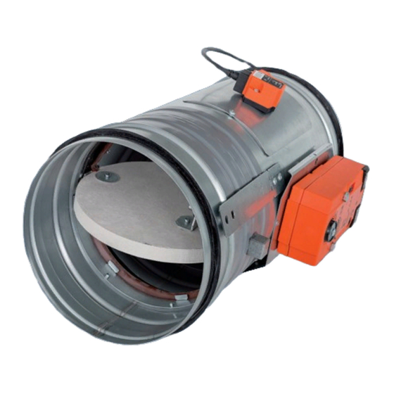
Fire damper
Hide thumbs
Also See for FDMC:
- General information manual (28 pages) ,
- Installation instructions manual (9 pages) ,
- Manual (16 pages)
Table of Contents
Advertisement
Quick Links
Advertisement
Table of Contents

Related Manuals for Mandik FDMC


Summary of Contents for Mandik FDMC
-
Page 2: Table Of Contents
These technical specifications state a row of manufactured sizes and models of fire dampers (further only dampers) FDMC. It is valid for production, designing, ordering, delivery, assembly and operation. 1. Description......................... 2. Damper Design..…......................3. Communication and control devices....…..............4. Dimensions, weights......................10 5. - Page 3 • Cycling test in class C 10000 acc. to EN 15650 • Corrosion resistant acc. to EN 15650 • ES Certificate of conformity No. 1391-CPR-0090/2014 • Declaration of Perfomance No. PM/FDMC/01/16/1 • Hygienic assessment of fire dampers - Report No. 1.6/13/16/1 Working conditions Exact damper function is provided under the following conditions: a) Maximum air circulation speed: 12 m.s...
-
Page 4: Damper Design
Temperature in the place of installation is permitted to range from - 30°C to + 50°C. Design with actuating mechanism FDMC is always equipped by electric actuating mechanism BFL (further only "actuating mechanism"). After being connected to power supply AC/DC 24V or 230V, the actuating mechanism displaces the damper blade into operation position "OPEN"... - Page 5 N L1 S1 S2 <5° <80° S1 S2 <5° <80° Nominal voltage AC 24 V 50/60 Hz AC 230 V 50/60 Hz DC 24 V Power consumption - motoring 3,5/5 W 2,5/4 W - holding 1,1/2,1 W 0,8/1,4 W Dimensioning 6,5/10 VA (Imax 4 A @ 5 ms) 4/6 VA (Imax 8,3 A @ 5 ms) Protection class...
- Page 6 Design with the communication and supply device Design with the communication and supply device BKN 230-24 and the actuating mechanism BFL 24-T-ST. It simplifies electrical wiring and interconnection of fire damper. It facilitates on site check and enables central control and checks of fire damper by means of a simple 2-conductor wiring.
-
Page 7: Communication And Control Devices
Nominal voltage AC 230V 50/60Hz Power consumption 3,5 W (operating position) Dimensioning 11 VA (including actuating mechanism) Protection Class Degree of protection IP 42 Ambient Temperature - 30 °C … + 50 °C Storage Temperature - 40 °C … + 50 °C Connection - mains Cable 0,9 m with EURO plug of 26 type - drive... - Page 8 K2 contact is on if all the damperss are open Current Failure K2 contact is on if the damper No. 1 is open K2 contact is on if all the No Failure open dampers are closed Function check can be done in the position OPERATION by means of pushing the TEST button. While the button is pushed, the flap blade is turning into the position FAILURE.
-
Page 9: Description
While a flashing green LED pilot light signalises flap blade motion towards the given position, the same pilot light reports reaching the required position when shining constantly. If the damper, with respect to the given time, does not reach the required position, then a red LED pilot light starts to flash and at the same time, the failure contact is active. -
Page 10: Dimensions, Weights
Dimensions BUILT-IN EDGE Damper casing Damper blade Inspection hole covering BAT thermoelectrical starting mechanism Actuating mechanism Weight and effective area 0,0036 0,0068 0,0092 0,0109 0,0129 0,0172 0,0222 0,0293 0,0374 0,0484 41,5 0,0630 0,0793 61,5 0,0821 0,1065... -
Page 11: Placement And Assembly
Blades overlaps Side without act. mechanism "a" Tab. 4.2.1 Fire dampers are suitable for installation in arbitrary position in vertical and horizontal passages of fire separating constructions. Damper assembly procedures must be done so as all load transfer from the fire separating constructions to the damper body is absolutely excluded. Back-to-back air-conditioning piping must be hung or supported so as all load transfer from the back-to-back piping to the damper is absolutely excluded. - Page 12 BUILT-IN EDGE BUILT-IN EDGE BUIL-IN EDGE The control mechanism has to be protected (covered) against damage and pollution during installation process. All fire dampers has to be closed during installation process. The damper body should not be deformed in the course of bricking in. Once the damper is built in, its blade should not grind on the damper body during opening or closing.
-
Page 13: Statement Of Installations
Statement of installations the fire dampers FDMC and their fire resistance Tab. 6.1.1. Mortar or gypsum EIS 60 Stuffing box + mastic and cement lime plate EIS 60 Installation next to wall - mortar or gypsum and EIS 60 mineral wool... - Page 14 ≥ 40 ≥ 100 POSITION: Fire damper FDMC Solid wall construction Mortar or gypsum Duct ≥ 50 ≥ 40 POSITION: Fire damper FDMC Solid wall construction ≥ 100 Mineral stone wool min. density 140 kg/m Fire protection mastic min. thickness 1 mm...
- Page 15 Gap between damper and construction is filled by mortar or gypsum and mineral wool POSITION: ● Wool is fixed to damper body and construction by fire protection Fire damper FDMC mastic. ● Mineral wool thickness = construction thickness + 50 mm Mortar or gypsum ●...
- Page 16 150* ≥ 40 POSITION: Fire damper FDMC * min. 110 - Concrete/ min. 125 - Aerated concrete Solid ceiling construction Mortar or gypsum Duct ≥ 50 ≥ 40 150* POSITION: Fire damper FDMC * min. 110 - Concrete/ min. 125 - Aerated concrete Solid ceiling construction Mineral stone wool min.
- Page 17 Profil is fixed by screws ≥3,5 mm with corresponding length. Distance between screws ≤200 mm. ≥ 40 POSITION: ≥ 100 Fire damper FDMC Gypsum plate Mineral wool (type depending on the type of construction) Mortar or gypsum Duct Installation opening has to be reinforced by profile (UW, CW).
- Page 18 Wool is fixed to damper body and construction by fire protection ● POSITION: mastic. Fire damper FDMC Mineral wool thickness = construction thickness + 50 mm ● ● Installation is valid for ceiling construction Mortar or gypsum...
-
Page 19: Suspension Of Fire Dampers
Mounting to the ceiling wall 36,6 Position: 58,0 Threaded rod M8 – M20 Washer Coupling Nut Anchor Hinge plate - min. thickness 10 mm Fire dampers can be suspended by using threaded rods and a mounting profiles. Load the suspension system depend on weight of the fire damper. Damper assembly procedures must be done so as all load transfer from the fire separating constructions to the damper body is absolutely excluded. - Page 20 Position: Fire damper Damping pad Extension piece Threaded rod Suspension ring Examples of using materials: Fire dampers can be suspended by using threaded rods and a mounting profiles. Load the suspension system depend on weight of the fire damper. Damper can be suspended from the ceiling construction or supported above the ceiling construc- tion.
- Page 21 Damper must be firmly connected with extension piece by screws or rivets. Position: Fire damper Damping pad Extension piece Threaded rod Mounting rail Washer Screw connection Mounting profile Bolt Screw or rivet...
-
Page 22: Pressure Loss
Pressure loss calculation [Pa] presure loss [m.s ] air flow speed in nominal damper section [kg.m ] air density coefficient of local pressure loss for the nominal damper section (see Tab. 8.2.1.) Determination of pressure loss by using diagram 8.2.1. = 1,2 kg.m Coefficient of local pressure loss 2,736 2,099 1,781 1,527... -
Page 23: Noise Data
Level of acoustic output corrected with filter A. + 10 log(S) + K [dB(A)] level of acoustic output corrected with filter A [dB] level of acoustic output L related to the 1 m section (see Tab. 10.3.1.) [m ] duct cross section [dB] correction to the weight filter A (see Tab. - Page 24 -4,5 -6,9 -10,9 -16,7 -24,1 -33,2 -43,9 -56,4 -3,9 -5,3 -8,4 -13,1 -19,5 -27,6 -37,4 -48,9 -3,9 -4,5 -6,9 -10,9 -16,7 -24,1 -33,2 -43,9 -4,0 -4,1 -5,9 -9,4 -14,6 -21,5 -30,0 -40,3 -4,2 -3,9 -5,3 -8,4 -13,1 -19,5 -27,6 -37,4 -4,5 -3,9 -4,9...
-
Page 25: Material
Damper bodies are supplied in the design made of galvanized plate without any other surface finishing. Damper blades are made of fire resistant asbestos free boards made of mineral fibres. Damper controls are made of galvanized materials with no other surface finish. Fasteners is galvanized. -
Page 26: Inspection, Testing
The appliance is constructed and preset by the manufacturer, its operation is dependent on proper installation and adjustment. Dampers are transported by box freight vehicles without direct weather impact, there must not occur any sharp shocks and ambient temperature must not exceed +40°C. Dampers must be protected against mechanic damages when transported and manipulated. -
Page 27: Ordering Key
Manual operation Without power supply, the damper can be operated manually and fixed in any required position. Release of the locking mechanism can be achieved manually or automatically by applying the supply voltage. It is recommended to provide periodical checks, maintenance and service actions on Fire Equipment by Authorized persons schooled by Producer. -
Page 28: Data Label
Data label is placed on the casing of fire damper. MANDÍK, a.s. Dobříšská 550 267 24 Hostomice Czech Republic FIRE DAMPER FDMC EI 60 (ve ho i o) S CLASSIFICATION: SIZE: DESIGN: SERIAL NUMBER: WEIGHT (kg): TPM083/12 Certificate: 1391-CPR-0090/2014 EN 15650:2010... - Page 29 MANDÍK, a.s. Dobříšská 550 26724 Hostomice Czech Republic Tel.: +420 311 706 706 E-Mail: mandik@mandik.cz www.mandik.cz The producer reserves the right for innovations of the product. For actual product information see www.mandik.com...
Need help?
Do you have a question about the FDMC and is the answer not in the manual?
Questions and answers