Table of Contents
Advertisement
Quick Links
Advertisement
Table of Contents

Related Manuals for palintest Micro 600 COND


Summary of Contents for palintest Micro 600 COND
- Page 1 Micro 600 Conductivity/TDS Meters ZI INST 1220...
- Page 2 Our contact details are on the last page of this manual. Palintest will not accept any responsibility for damage or malfunction to the meter caused by improper use of the instrument. The information presented in this manual is subject to change without notice...
-
Page 3: Table Of Contents
Advanced Setup Functions Advanced Setup Overview Select Cell Constant Getting Started Automatic Calibration Description of Keypad Functions (Micro 600 COND only) Description of LCD Annunciators Setting the TDS Factor Inserting & removing the (Micro 600 TDS only) rubber armour/stand Temperature Coefficient... -
Page 4: Introduction
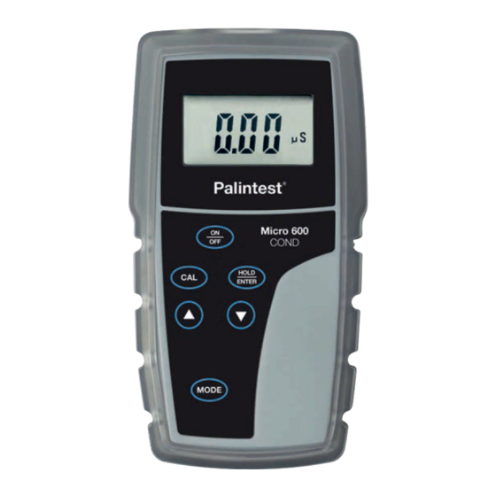
Introduction 1.0 Introduction Thank you for purchasing the Micro 600 COND or Micro 600 TDS meter. These microprocessor-based handheld meters are economical and easy to use with a large custom LCD (Liquid Crystal Display) for clear and easy reading. The Micro 600 COND measures conductivity (µS/cm or mS/cm) and temperature (°C) while the Micro 600 TDS measures total dissolved solids (TDS) in... -
Page 5: Getting Started
2 Parts per million (ppm) (Micro 600 TDS). Parts per thousand (ppt) (Micro 600 TDS). 3 Milli-Siemens/cm (mS) or micro-Siemens/cm (µS) indicator (Micro 600 COND only). 4 Temperature indicator. 5 “LO” = low battery condition. 6 “HO” = HOLD function is activated and reading is frozen. -
Page 6: Inserting & Removing The Rubber Armour/Stand
Getting Started 2.3 Inserting & removing the rubber armour/stand 1 To remove meter from rubber armour, push out from the bottom edges of meter until it is completely out of boot. Ensure that your electrode cables are not connected. See Figure 1. 2 To insert meter into armour, slide in from the top of meter before pushing the bottom edges of meter down to set it into position. -
Page 7: Battery Replacement
Getting Started 2.5 Battery Replacement A “LO” annunciator in the LCD alerts you when battery power is running low. Caution: Power off the meter before replacing battery. “LO” Battery Condition 2.6 Connecting the Electrode 2.5mm mini phono 1 To connect the electrode, align the connector for temperature slots with the posts of meter’s socket and rotate connector clockwise until it locks. -
Page 8: Switching The Meter On
Getting Started 1 DO NOT measure or calibrate without the protective probe guard in place. 2 Immersion above the protective guard Immerse is not recommended. The cable can be probe submerged briefly but is not designed beyond upper for continuous immersion. steel band See “Probe Care and Maintenance”... -
Page 9: Changing Mode
Getting Started Micro 600 COND Measurement Mode Micro 600 TDS Measurement Mode 2.9 Changing Mode To switch between conductivity and TDS measurement mode and temperature measurement mode, simply press the MODE key. The annunciator will indicate the measurement mode you are in. -
Page 10: Calibration
Calibration 3.1 Important Information on Meter Calibration The Micro 600 COND and Micro 600 TDS have five measuring ranges listed below. Each range can be calibrated to one point per range (five total points if each range is calibrated). Calibration is recommended for each range that will be used. -
Page 11: Preparing The Meter For Calibration
(deionised water is ideal). 3.3 Selection of Auto or Manual Calibration (Micro 600 COND) The Micro 600 COND is capable of automatic or manual calibration. The factory default setting is automatic. In the automatic calibration mode, the Micro 600 COND will automatically select one of (4) calibration standard values (see below) depending on the range and normalisation temperature being used. -
Page 12: Using Automatic Calibration (Micro 600 Cond)
1. See Section 5.3 Advanced Setup to modify automatic or manual calibration. 3.4 Using Automatic Calibration (Micro 600 COND) In Automatic Calibration mode, the COND can accept up to 4 calibration points with maximum of 1 point per measurement range. Note: values in the 0.00 to 20.00 µS/cm range cannot be calibrated in Auto Calibration mode. -
Page 13: Manual Calibration
Calibration NOTES: 1 To protect from erroneous calibrations, the allowable tolerance is ±40% of the factory default value. If calibration is attempted with standards that fall outside this tolerance range, the error message “Err 1” is indicated and meter will return to measurement mode. For example, a 40% tolerance of a 1413 µS/cm standard, is 848 µS/cm to 1978 µS/cm. -
Page 14: Temperature Calibration
Calibration 5 When the value is stable, press s or t as needed to adjust the value to match your calibration standard. 6 Press ENTER to confirm the adjusted value. [CO] will appear briefly indicating that the calibration was successful. The meter returns to measurement mode. 7 Repeat steps 1-6 as needed with additional calibration standards. -
Page 15: Measurement
Measurement 4.0 Measurement Your meter is capable of taking measurements that incorporate temperature measurements automatically (most common) or using a temperature which you input manually (rare). 4.1 With Automatic Temperature Compensation (ATC) To compensate your reading using temperature values as measured by your electrode, simply attach the phono plug of the electrode to the meter. -
Page 16: Using Manual Ranging Function
Alternatively, to override auto-ranging you can manually select a specific range by pressing s successively for each measurement range. The five ranges are: Micro 600 COND Micro 600 TDS Conductivity Range TDS Range (using 0.5 TDS factor) 0 - 20.00 µS/cm... -
Page 17: Hold Function
Measurement 4.5 HOLD Function For prolonged observation of a reading, press HOLD while in measurement mode to freeze the display. 1 To hold a measurement, press HOLD while in measurement mode. [HO] will appear on the display. 2 To release the held value, press the HOLD again. -
Page 18: Advanced Setup Functions
Advanced setup allows customisation settings such as; selecting electrode’s cell constant, normalisation temperature, temperature coefficient, TDS factor (Micro 600 TDS), automatic or manual calibration (Micro 600 COND), single-point or multi-point calibrations (COND and TDS), and to reset meter to factory default. -
Page 19: Select Cell Constant
5 Press s or t to move to the next setup function or press CAL to exit to measurement mode. 5.3 Automatic Calibration (Micro 600 COND only) Select automatic calibration “YES” for easy calibration of (4) factory pre-set conductivity calibration standards (see Section 3.3 Table 1). -
Page 20: Setting The Tds Factor (Micro 600 Tds Only)
Advanced Setup Functions 5.4 Setting the TDS Factor (Micro 600 TDS only) The concentration of salts dissolved in solution increases the conductivity. This relationship varies from salt to salt and is roughly linear over a given range for a given salt. The TDS conversion factor is the number used by the meter to convert from conductivity to TDS. -
Page 21: Normalisation Temperature
Advanced Setup Functions 5.6 Normalisation Temperature You can set the meter to normalise its measurements to a temperature of either 25°C or 20°C. Default value is 25°C. 1 Enter advanced setup as described in Section 5.1. 2 Press s or t until [t.nr°C] appears. Press ENTER. 3 Press s or t to select [25.0°C] or [20.0°C]. -
Page 22: Restore Factory Default Values
Advanced Setup Functions 5.8 Restore Factory Default Values Use this function to reset all parameters to factory default settings. This clears all calibration data and any other setup functions you might have changed. IMPORTANT: Once activated the settings and calibration data will be erased and can not be undone. 1 Enter advanced setup as described in Section 5.1. -
Page 23: Probe Care And Maintenance
Probe Care and Maintenance 6.0 Probe Care and Maintenance Keep the probe clean. Rinse the probe twice, and gently swirl it while you take readings. For best results, soak a dry probe for at least 5-10 minutes before calibration. Rinse the probe with clean water before storing. -
Page 24: Troubleshooting
Troubleshooting Problem Cause Solution Batteries are not installed, were Install batteries with correct +/- polarity. No display improperly installed, or are too weak Replace with new batteries “LO” displays Low battery Replace batteries in the LCD a) Air bubbles in probe a) Tap probe to remove bubbles b) Dirty probe b) Clean probe &... -
Page 25: Specification/Features
Specification/Features COND 0 to 20.00 (0.01) µS/cm 20.0 to 200.0 (0.1) µS/cm Conductivity Ranges 200 to 2000 (1) µS/cm (Resolution) 2.01 to 20.00 (0.01) mS/cm 20.1 to 200.0 (0.1) mS/cm 0 to 10.00 (0.01) ppm 10.0 to 100.0 (0.1) ppm 100 to 1000 (1) ppm TDS Ranges (Resolution) 1.01 to 20.00 (0.01) ppt... -
Page 26: Conductivity Theory
Conductivity Theory Conductance is a quantity associated with the ability of primarily aqueous solutions to carry an electrical current, I, between two metallic electrodes when a voltage V is connected to them. Though water itself is a rather poor conductor of electricity, the presence of ions in the water increases its conductance considerably, the current being carried by the migration of the dissolved ions. - Page 27 Conductivity Theory Since the basic unit of electrical resistance is the ohm, and conductance is the reciprocal of resistance, the basic unit of conductance was originally designated a “mho” - ohm spelled backwards - however, this term has been replace by the term “Siemens”.
-
Page 28: Calibration Tips
Calibration Tips You only need one calibration for measurement throughout the entire range of the meter. If a range was not calibrated, the meter automatically detects the closest range calibrated and uses that calibration information. However, only the ranges that were calibrated have maximum accuracy. If you are measuring in ranges near to or greater than 20 mS/cm (10 ppt), or near to or lower than 100 µS/cm (50 ppm), suggested calibration frequency is at least weekly. -
Page 29: Calculating Tds Conversion Factor
Calculating TDS Conversion Factor You can calibrate your meter using TDS calibration standard solutions. The calibration standard only needs to give the TDS value at a standard temperature such as 25°C. To determine the conductivity-to-TDS conversion factor use the following formula: Factor = Actual TDS ÷... -
Page 30: Calculating Temperature Coefficients
Calculating Temperature Coefficients To determine the temperature coefficient of your sample solution use this formula: = 100 x - 25) - C - 25) Where: = Temperature coefficient 25 = 25°C = Conductivity at Temp 1 = Conductivity at Temp 2 = Temp 1 = Temp 2 NOTE: A controlled temperature water bath is ideal for this procedure. -
Page 31: Replacement Parts And Accessories
3000ppm (442) TDS Solution (500ml) PT 142/8 300ppm (442) TDS Solution (500ml) PT 142/9 50ppm (442) TDS Solution (500ml) PT 142/10 Deionised Water Wash Solution (500ml) PT 1250 Micro 600 COND Complete Kit PT 1220 Micro 600 TDS Complete Kit PT 1210... -
Page 32: Warranty And Certification
Warranty and Certification 14.0 Warranty The Palintest Micro 600 COND/TDS Meter is guaranteed for a period of three years from date of purchase - its associated Conductivity/TDS electrode is guaranteed for a period of six months from date of purchase. This guarantee excludes accidental damage, or damage caused by unauthorised repair or misuse. - Page 33 For more information on Palintest products, contact your nearest Palintest office or visit our website Palintest Ltd Palintest China Palintest House, Kingsway, Team Valley, Room 1711, Fanli Mansion, Gateshead, NE11 0NS 22 Chaowai Street, Chaoyang District, Tel: +44 (0)191 491 0808...
Need help?
Do you have a question about the Micro 600 COND and is the answer not in the manual?
Questions and answers