palintest Micro 800 Instruction Manual
Optical dissolved oxygen meter
Hide thumbs
Also See for Micro 800:
- Operating instructions manual (14 pages) ,
- Operating instructions manual (15 pages)
Table of Contents
Advertisement
Quick Links
Advertisement
Table of Contents
Troubleshooting

Subscribe to Our Youtube Channel
Related Manuals for palintest Micro 800


Summary of Contents for palintest Micro 800
- Page 1 Micro 800 Optical Dissolved Oxygen Meter Instruction Manual...
- Page 2 Please read this agreement carefully. Palintest Ltd grants you a limited license to use the software embedded in the devices (the “Software”) in binary executable form in the normal operation of the products. Title, ownership rights and intellectual property rights in and to the Software remain in Palintest Ltd.
-
Page 3: Table Of Contents
4. OVERVIEW OF THE OPERATING SYSTEM ......................8 4.1..................8 NITIAL WITCH ANGUAGE AND LOCK ETUP 5. CONNECTING AN MICRO 800 PROBE ........................9 6. TAKING MEASUREMENTS ............................9 6.1. ? ..........................9 6.2............................10 REND NDICATION 6.3. - Page 4 RIOR ETURN 15.2........................34 ECONTAMINATION ERTIFICATE 16. TROUBLESHOOTING ............................. 35 17. DECLARATION OF CONFORMITY ........................36 18. APPENDIX 1. THE TECH BEHIND MICRO 800 ....................37 18.1..........................37 RINCIPLE OF PERATION 18.2.............................. 37 ENSOR 19. APPENDIX 2. DO FLOW THROUGH CELL ......................39 19.1.
-
Page 5: Introduction
With the Micro 800 system, up to 3000 sets of readings tagged with time, date and position can be taken, then downloaded from the Micro 800 Meter onto a PC using the included USB cable and Micro 800 Link software utility. -
Page 6: What's In The Box
2.1. The Micro 800 Meter and the Environment The Micro 800 Meter is designed to be used outdoors and is rated to IP67, that is to say it is waterproof but it is not designed for submersion. In order to prevent accidental dunking or loss, a lanyard is supplied. -
Page 7: Battery Installation And Care
3.2. Battery Life A set of fresh alkaline cells will give over 20 hours use in the Micro 800 Meter. A fully charged set of 2500mAh NiMH cells will give up to 40 hours use in the Micro 800 Meter. -
Page 8: Overview Of The Operating System
Rev 1 4. Overview of the Operating System The operating software in the Micro 800 Meter has been designed for simple, intuitive use. Similarly, a great deal of development work has been put into simplifying and automating the calibration procedures in the Micro 800 Meter in order to allow normal field operatives (as opposed to trained lab technicians) to achieve quick and accurate results. -
Page 9: Connecting An Micro 800 Probe
The Micro 800 Meter is designed to operate in conjunction with the Micro 800 Probe. To connect a Micro 800 Probe, align the key slot of the Micro 800 Probe plug with the Micro 800 Meter socket, then press the plug into the socket and tighten the retaining collar. -
Page 10: Trend Indication
It is a fundamental, practical requirement in the field of water quality monitoring that test measurements taken at different temperatures can be compared. In order to facilitate this, the Micro 800 Probe automatically applies corrections for temperature wherever required. -
Page 11: Gps Reception
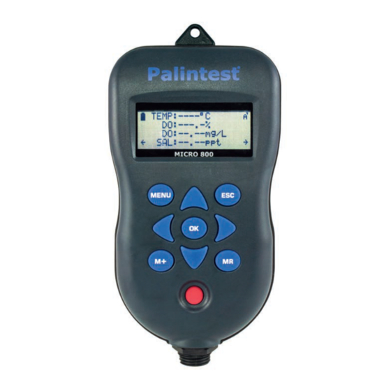
7. GPS Reception The Micro 800 Meter contains a built-in GPS receiver and antenna. The antenna is situated at the top of the case, just behind the PALINTEST Logo. For optimum signal reception, the antenna must be able to ‘see’ a reasonably large amount of the sky. -
Page 12: Memory Mode
As each reading is saved, a numeric memory location ‘Tag’ will be briefly displayed which you can note down. This Tag can be used to identify readings at a later date, both on the Micro 800 Meter and when using Micro 800 Link software. 8.2. Recalling and Viewing Saved Readings To recall your readings, press the MR key. -
Page 13: Clearing The Memory
To exit this screen press the ESC key or the left arrow key. 8.4. Clearing the Memory The memory within the Micro 800 Meter is capable of storing up to 3000 full sets of readings. To clear the entire memory, switch the Meter off, hold down the M+ key, then switch the Meter back on. -
Page 14: Important Information About Memory Mode
The same rules apply when data is output to a PC running Micro 800 Link Software via the USB cable. The data that is output is always as per the Meter’s current configuration. You can output the data as many times as you like in various Meter configurations. -
Page 15: Setting Units Of Measurement
Micro 800 Optical DO Instruction Manual Rev 1 9. Setting Units of Measurement To alter the way the Micro 800 Meter displays readings, press the MENU key to get to the Main Menu, then choose Settings. The Settings Menu will be displayed. Settings Menu Units Time &... - Page 16 British Isles. The system is not valid elsewhere. If you need to see the position displayed in UTM (Universal Transverse Mercator) co- ordinates, this is available in the Micro 800 Link software. © 2014 Palintest Ltd.
-
Page 17: Cleaning The Probe
Micro 800 Optical DO Instruction Manual Rev 1 10. Cleaning the Probe The Sleeve on the Micro 800 Probe is easily removed by unscrewing to allow cleaning of the electrode. With the Sleeve removed, the electrode is very vulnerable, so please handle the Probe with extreme care. -
Page 18: About Calibration
A great deal of development work has been put into simplifying and automating the calibration procedures in the Micro 800 Meter in order to allow normal field operatives (as opposed to trained lab technicians) to achieve quick and accurate results. -
Page 19: Resetting To Factory Calibration Defaults
DO Zero, DO 100% and EC. 11.3. Calibration Data Storage Each Micro 800 Probe contains its own microprocessor and memory. All calibration data, including the GLP data, is stored within the Probe’s memory. When a Probe is connected to a Meter, this data is transferred for display and logging. -
Page 20: Do/Ec Electrode Calibration And Maintenance
Switch the Micro 800 Meter on and wait until the DO reading is completely stable. The longer you can leave the probe to achieve thermal equilibrium before proceeding, the better. -
Page 21: Checking And Calibrating The Do 100% Saturation Point In Moist Air
5. If re-calibration is necessary, refer back to the screen shown in 12.4.4 above and select DO100% 6. Wait while the Micro 800 Meter carries out the calibration procedure. 7. When the ‘Calibrating 100%’ screen (shown above) is displayed, press OK then ESC repeatedly to return to normal reading mode. -
Page 22: Replacing The Do Cap
12,880µS/cm. These values have been chosen to allow accurate readings to be taken in a variety of water types. For taking measurements in fresh surface or ground water, use Palintest conductivity solution. If this is not available, use a third party 1413µS/cm EC Calibration Standard. - Page 23 2. Tap the probe to remove any air bubbles that may be adhering to the sensor. 3. Switch the Micro 800 Meter on and wait until the temperature and EC measurements are completely stable. The longer you can leave the probe to achieve thermal equilibrium before proceeding, the better.
-
Page 24: Errors During Calibration
Micro 800 Optical DO Instruction Manual Rev 1 key. The screen will change to: PLEASE WAIT Stabilising 000% 8. When the ‘Calibrating 100%’ screen is displayed, press OK. Special Notes: The Calibration Standard value is stored in the Probe, not the Meter. If you use one Meter with several different Probes, you will have to set the Calibration Standard value for each probe individually during calibration. -
Page 25: Micro 800 Link Pc Software
These are the 'Micro 800 Meter' driver and a 'USB Serial Port' driver. 13.3. Driver Installation Connect the Micro 800 Meter to your PC using the USB cable provided. The ‘Found New Hardware’ wizard on your PC should activate automatically. -
Page 26: Running Micro 800 Link
13.8. Saving Logged Data Once a set of logged data has been uploaded from the Micro 800 Meter, it can be saved on your PC as a Raw Data file. These files use a proprietary Palintest format and are saved with a .omf (oxygen meter file) extension. -
Page 27: Retrieving Logged Data
.omf extension. Useful Tip: Once you have saved the logged data, it is a good idea to clear the Micro 800 Meter’s memory so next time you log data, you don’t get both your old data and new data uploaded to your PC. -
Page 28: Exporting Excel ® Files
Micro 800 Optical DO Instruction Manual Rev 1 A typical Text Report cover page follows: MICRO 800 LINK REPORT ---------------------------- File name: C:\Test\3 day test 024690136.txt Operator name: G.E.M. Company name: Palintest Ltd Site name: Test Site 4 Start date and time:... -
Page 29: Exporting Google Files
® Excel . When opening a .xls file created by Micro 800 Link for the first time, Excel automatically run a ‘Text Import Wizard’. Follow the three simple steps to import the file. Save the file afterwards as a ‘Microsoft Excel Workbook’. -
Page 30: Google Example
Micro 800 Optical DO Instruction Manual Rev 1 13.15. Google Example Zooming in on the satellite photos in Google Earth is a great way to spot potential sources of pollution. If one of the readings you have taken shows an abnormality, the chances are that you will be able to spot the possible source of the problem (a riverside factory for example) directly on the satellite photo. -
Page 31: Specification
Weight (including cable) *Micro 800 Probes are supplied as standard with a 3M cable. Extension cables with in-line connectors are available in 5M, 10M and 30M lengths, but are limited to a maximum of 10M immersion depth by the integrity of the connectors. -
Page 32: Micro 800 Meters Specification
5 x AA cells. Alkaline or Ni-MH rechargeable Power Supply Alkaline > 20 hours. Ni-MH > 40 hours Battery Life -20˚C to +70˚C Operating Temperature IP67 Protection Class Palintest Ltd reserves the right to change specifications without notice © 2014 Palintest Ltd. www.palintest.com Page 32 of 41... -
Page 33: Limited Warranty
Rev 1 15. Limited Warranty All Palintest Meters are guaranteed for three years, Probes, Flow-Through Cells and individual electrodes are guaranteed for one year from date of purchase against defects in workmanship and materials when used for their intended purpose and maintained according to instructions. -
Page 34: Decontamination Certificate
Micro 800 Optical DO Instruction Manual Rev 1 15.2. Decontamination Certificate Please print this certificate, complete all sections, and enclose it with any returned equipment. Decontamination Certificate Company Name: ____________________________________ Address: __________________________________________________________________________ _____ __________________________________________________________________________ _____ __________________________________________________________________________ _____ __________________________________________________________________________ _____ Postal code: ___________________________________... -
Page 35: Troubleshooting
This section details some of the common difficulties you may encounter when using the Micro 800 Meter, Micro 800 Probes and Micro 800 Link software. Try all the suggested remedies. If your problem is still unresolved, contact our Service Department (support@palintest.co.uk). -
Page 36: Declaration Of Conformity
The EC electrode may be dirty. Clean the EC electrode then recalibrate. 17. DECLARATION OF CONFORMITY Palintest Ltd declares that the equipment described herein is in compliance with the essential requirements and other relevant provisions of Directives 2004/108/EC and 1999/5/EC. -
Page 37: Appendix 1. The Tech Behind Micro 800
Housed in a resin filled, marine grade aluminium body that measures just 8mm (0.3”) diameter by 13mm (0.5”) long, the fully waterproof Micro 800 Sensor Module contains blue excitation and red reference LEDs, optical filters, a photon detector, temperature sensor, driver circuitry and high gain amplification circuitry. - Page 38 This incredibly fast reading time increases the useful life of the luminophore considerably. Another technique used to prolong the life of the luminophore in the Micro 800 is variable excitation brightness. When the luminophore is new, the brightness of the excitation is reduced to a minimum in order to prevent unnecessary photo bleaching.
-
Page 39: Appendix 2. Do Flow Through Cell
19. Appendix 2. DO Flow Through Cell 19.1. Introduction The Palintest DO Flow Through Cell (DO Flowcell) is designed for use with the Micro 800 Probe and most third party pumping device. The Flowcell allows sample water to flow up through and around the Micro 800 Probe, passing over both the DO and EC sensors simultaneously. -
Page 40: Caution
In no event will Palintest Ltd be liable for any incidental, special, indirect or consequential damages resulting from the misuse of this equipment. -
Page 41: Appendix 3. Probe Hanger
Probe on a separate steel cable using a Probe Hanger. To attach a Probe Hanger to an Palintest Probe, first remove the cable gland collar (if fitted) then remove the top plastic nut that is attached to the top of the Probe and slide them both a little way up the cable.
Need help?
Do you have a question about the Micro 800 and is the answer not in the manual?
Questions and answers