
Subscribe to Our Youtube Channel
Related Manuals for HOKUYO AUTOMATIC UST-05LN


Summary of Contents for HOKUYO AUTOMATIC UST-05LN
- Page 1 Document No: C-41-02490-9 Scanning Laser Range Finder UST-05LN/UST-05LA User’s Manual...
-
Page 2: Table Of Contents
2.4 Wiring ..............................6 2.5 Configuration ............................6 2.6 Inspection and maintenance ......................... 6 3. Product overview ............................7 3.1 Features of UST-05LN/UST-05LA ....................... 7 3.2 Components of UST-05LN/UST-05LA....................8 3.3 Operation principle ..........................10 3.4 Area configuration ..........................11 3.5 Area switching............................ - Page 3 Document No: C-41-02490-9 3.16.2 Laser pulse skip function ......................26 4. Application examples of the UST ......................27 4.1 Access protection (Horizontal application Stationary) ..............27 4.2 Protrusion detection (vertical placement) ..................28 4.3 Area protection (Mobile) ........................29 5. Installation ..............................31 5.1 Light interference ..........................
-
Page 4: Introduction
Document No: C-41-02490-9 1. Introduction This user’s manual is designed with the purpose of providing guidelines and instructions for the machine user or system designer while operating, installing, wiring and servicing the UST sensor (UST-05LN, UST-05LA). 1.1 About this document/manual The UST’s features, installation and handling method are described in this document. -
Page 5: Cautions
Document No: C-41-02490-9 1.4 Cautions The UST has been shipped upon strict quality control. If you find any defect in the product contact the nearest distributor or sales representative. Hokuyo cannot be held responsible for damages or failure due to misuse of the product. ... -
Page 6: Safety Precautions
Document No: C-41-02490-9 2. Safety precautions Make sure to read the following safety precautions for the correct use and operation of the UST. 2.1 General precautions The UST is not a safety device. Do not use this sensor for the purpose of protecting humans. ... -
Page 7: Wiring
Document No: C-41-02490-9 Avoid direct sunlight as it may cause sensor malfunction. Refer to chapter 5 (light interference) for details. Increasing the response time will also increase the stability of the UST. However, this will reduce the detection capability towards moving objects. User must perform pre-operation tests before using this function. -
Page 8: Product Overview
Document No: C-41-02490-9 3. Product overview This chapter describes the features and properties of UST-05LN/UST-05LA. 3.1 Features of UST-05LN/UST-05LA Detection range : Maximum 5m Detection angle : 270° Angular resolution : 0.5° 31 set of areas (configurable) ... -
Page 9: Components Of Ust-05Ln/Ust-05La
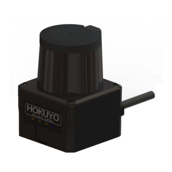
Document No: C-41-02490-9 3.2 Components of UST-05LN/UST-05LA Figure 3-1 shows the components of UST-05LN/UST-05LA Optical window Housing LED display Cable USB Connector Figure 3-1 UST-05LN/UST-05LA components Figure 3-2 shows the scanning range and detection zone origin of the UST, while figure 3-3 shows its... - Page 10 Document No: C-41-02490-9 Detection zone origin Scanning range Figure 3-2 Scanning range and detection zone origin (Top view) Detection plane marking Detection plane Figure 3-3 Detection plane of UST (Back view)
-
Page 11: Operation Principle
Document No: C-41-02490-9 3.3 Operation principle Output region 3 Output region 2 270° Output region 1 0° Figure 3-4 Scanning range Figure 3-4 shows the scanning range of the UST. The sensor emits pulsed laser beams which reflect on a rotating mirror forming a fan-like scanning pattern over 270 °... -
Page 12: Area Configuration
Document No: C-41-02490-9 The operation principle of TOF is shown in schematic diagram (Figure 3-5) below Figure 3-5 TOF operation principle 3.4 Area configuration The detection area of the UST consist the output regions 1, 2, and 3 respectively. Output 1 to Output 3 can be configured by using the Area Designer application software through a USB cable. -
Page 13: Area Switching
Document No: C-41-02490-9 For the Dependent method, the following shapes are defined: Straight line, Fan, and Ratio (numerical input is also available). In the dependent method, output 1 serves as a basis for output 2. Similarly, output 2 can be set as the basis for output 3. - Page 14 Document No: C-41-02490-9 Table 3-1 Input states and corresponding area number Area Number Input1 Input2 Input3 Input4 Input5 Laser off Area1 Area2 Area3 Area4 Area5 Area6 Area7 Area8 Area9 Area10 Area11 Area12 Area13 Area14 Area15 Area16 Area17 Area18 Area19 Area20 Area21 Area22 Area23...
-
Page 15: Detection Condition
Document No: C-41-02490-9 3.6 Detection condition In the configured area, if the detectable size (width) is more than the minimum detectable objects, an output signal is displayed (for setting refer to section 3.9). The width of detectable object can be calculated as shown in figure 3-8. -
Page 16: On /Off Delay
Document No: C-41-02490-9 3.7 ON /OFF delay ON delay and OFF delay of the output signal can be set by using Area Designer within the range of 1scan (66ms) to 128scan (3241ms) (default is 1scan (66ms)) ON delay is the response time changing from OFF state to ON state. OFF delay is the response time changing from ON state to OFF state. - Page 17 Document No: C-41-02490-9 2. Schematic diagram when 2scan OFF delay setting :Object absent :Object present Output judgment Output judgment Output judgment 1scan (Object absent) 2scan (Object absent) 3scan (Object present) 3. Schematic diagram without ON delay setting :Object absent :Object present Output judgment Output judgment 1scan (Object present)
-
Page 18: Hysteresis Function Of Detection Area
Document No: C-41-02490-9 3.8 Hysteresis function of detection area When a sensor detects an object near the boundary of the detection area, outputs 1 to 3 may oscillate (changing to ON/OFF state) repeatedly. To prevent such oscillation, sensor has a hysteresis function that temporarily increases the area size. - Page 19 Document No: C-41-02490-9 Laser pulse skip Laser pulse skip can be set. Select from below setting. (For details, refer to section 3.16) Setting Description No laser pulse skip. Laser pulse skip. Motor speed Motor speed ratio of UST can be set. Select from below setting. * Can select only when motor sync mode is independent.
-
Page 20: Output
Document No: C-41-02490-9 3.10 Output The UST has 3 types of outputs as below. 3.10.1 Output 1 to Output 3 Output 1: When the object is detected in the output region 1, output 1 will switch to OFF state. Output 2: When the object is detected in the output region 2, output 2 will switch to OFF state. Output 3: When the object is detected in the output region 3, output 3 will switch to OFF state. -
Page 21: Indicator Lamp
Document No: C-41-02490-9 3.12 Indicator lamp 4 LED display indicates the UST status. This LED display is located in the front of the UST as shown in Figure 3-11. Table 3-4 shows the description of the LEDs. Power supply display (Blinks during start up, configuration and malfunction state) Output 1... -
Page 22: Laser Spot
Document No: C-41-02490-9 3.13 Laser spot The laser spot of the UST is as shown in figure 3-12. The spread of laser spot differs on the front and side of the unit. The size value is for reference only. Front view 80×5mm 200mm Floor surface... -
Page 23: Data Logging
Document No: C-41-02490-9 3.14 Data logging By connecting the UST with the Area Designer software for data logging (the log includes: distance, intensity, output states, recording time), it is possible to record and play of log data. The operating steps are as follows. -
Page 24: Playing Log Data
Document No: C-41-02490-9 3.14.2 Playing log data Follow the steps below for playing log data. ① Click play button as shown in figure 3-15. (Cannot play the log data until measurement display button is OFF) Play log data Measurement display [Ctrl+0] Figure 3-15 Play log data button ②... -
Page 25: Sd Card Log Function (For Ust-05La Only)
Document No: C-41-02490-9 3.15 SD card log function (for UST-05LA only) With this function the UST by itself can record data log (distance, intensity, output states and recording time) using an internal microSD card without connecting to Area Designer. The recorded log data can be saved (downloaded) and played in the Area Designer. -
Page 26: Laser Emission Skip Function
Document No: C-41-02490-9 3.16 Laser emission skip function When this is function is activated, it reduces the probability of light interference. There are two types of laser emission skip function. Scan skip function Laser pulse skip function 3.16.1 Scan skip function When scan skip function is activated, it stops laser emission of the set scan number during rotation. -
Page 27: Laser Pulse Skip Function
Document No: C-41-02490-9 In case when the laser of the UST affects the other products operation (causes light interference in other products), activate scan skip function to reduce affects on other products. 3.16.2 Laser pulse skip function When laser pulse skip function is activated, laser emission period will change from approx. 9usec to approx. -
Page 28: Application Examples Of The Ust
Document No: C-41-02490-9 4. Application examples of the UST In this chapter will explain giving some application examples that can be used. Before installing, the user has to decide the main purpose for using the UST. Next, decide the suitable installation place as well as required detection area size, etc. -
Page 29: Protrusion Detection (Vertical Placement)
Document No: C-41-02490-9 4.2 Protrusion detection (vertical placement) The UST can be installed vertically. Figure 4.2 shows the application of protrusion detection. For the protrusion detection of cargo from the shelf of an automatic warehouse, install the sensor vertically on the back side so that the detection surface covers the back side of the shelf. If cargo enters the detection surface a warning signal can be triggered, and equipment for position adjustment of cargo can be operated. -
Page 30: Area Protection (Mobile)
Document No: C-41-02490-9 4.3 Area protection (Mobile) The UST can be used for mobile applications. Figure 4-3 shows an example of an AGV (Automatic Guided Vehicle). The UST is installed on an AGV and detects the objects while travelling along a fixed route. Output signals 1 to 3 can be used in order to reduce the speed and to stop the AGV. - Page 31 Document No: C-41-02490-9 Output region 2 Output region 1 Output region 3 Figure 4-4 Example of area switching of AGV while turning right Check that there is no object or background in the configured area. If any object is detected then output 1 to 3 will remain in OFF state.
-
Page 32: Installation
Document No: C-41-02490-9 5. Installation This chapter describes precautions during sensor installation. The UST can be fixed to a surface using either the back mounting plate or the bottom mounting plate and each plate provided with two screw holes. This mounting plate is used as a frame ground (FG). Mount the sensor on a stable structure. -
Page 33: Mutual Interference
Document No: C-41-02490-9 5.2 Mutual interference Extra precautions are required while using two or more identical UST sensors because pulsed laser signals from identical UST units could lead to false detection. Figures below show the installation method for avoiding mutual interference. a) Changing the height of installation Displace the installation position up and down;... - Page 34 Document No: C-41-02490-9 5°or more 5°or more Detection plane Detection plane Figure 5-5 Parallel installation C) Adding shield in between UST By adding a shield in between the UST units, laser beam cannot reach the opposite sensor so this will avoid possible mutual interference Detection plane Detection plane...
-
Page 35: Synchronous Operation
Document No: C-41-02490-9 5.3 Synchronous operation When operating two or more UST units within a short distance mutual interference may occur. To prevent mutual interference between them, the rotation of the USTs can be synchronized. A maximum of 3 UST units can be operated by delaying the rotation by 90 degrees (however, this cannot guarantee 100% prevention of mutual interference, depending upon the installation condition, background condition, etc., of each UST. -
Page 36: Wiring
Document No: C-41-02490-9 6. Wiring This chapter describes precaution to take during wiring. 6.1 Precautions During electric wiring make sure that all devices are disconnected from power supply. Switch off all the power supply during wiring. 6.2 Power supply Make sure that power supply is either DC 12V or DC 24V (operation voltage range 10V to 30V) In case rated output voltage exceeds this range, UST could be damaged. -
Page 37: Wire Color And Function
6.3 Wire color and function Table 6-1 shows the color of each lead wire, signal name, function, etc. Table 6-1 Wire color and function Signal Description Color Function UST-05LN UST-05LA UST-05LN UST-05LA Brown +VIN Power Power Supply: DC 12V or DC 24V... -
Page 38: Input/Output Circuit
Document No: C-41-02490-9 Note: Color names inside brackets indicate dual color cable. Keep the input wires open or connected to input Com+ (red) if not in use. Keep the output wires open or connected to output Com- (gray) if not in use. Input/Output direction is defined from the sensor point of view (sensor as reference). -
Page 39: Rs422 (For Ust-05La Only)
Document No: C-41-02490-9 6.5 RS422 (For UST-05LA only) Figure 6-3 shows the example of connection of RS422 D-SUB 9pin male D-SUB 9pin Signal Pin No. Wire color Signal Pink RS422 GND Yellow (Red) RS422 TXD+ Yellow (Black) RS422 TXD- Light Blue (Red) RS422 RXD+ Light Blue(Black)... -
Page 40: Ust Area Designer Application Software
Document No: C-41-02490-9 7. UST Area Designer application software Install application software (Area Designer) in a supported operating system and connect UST using a USB cable. Area Designer has the following functions: Configuration of detection area Configuration of various UST functions ... - Page 41 Document No: C-41-02490-9 Operation is not guarantee even if the system requirements are fulfilled. Read thoroughly the Instruction manual of Area Designer for configuring UST. Instruction manual can be loaded from the help menu of Area Designer. Cover the sensor’s USB connector with the protection cap while using UST.
-
Page 42: Inspection And Maintenance
Document No: C-41-02490-9 8. Inspection and maintenance Inspection and maintenance are necessary for safety operation. User must ensure that inspection and maintenance are carried out as specified. Before performing inspection and maintenance, confirm the following items. The machine monitored by the UST is switched OFF. ... -
Page 43: Pre-Operation Inspection
Document No: C-41-02490-9 8.1 Pre-operation inspection After configuration is completed, pre-operation inspection test should be performed using a test piece. User should perform this inspection without connecting the sensor to the system. Table 8-1 shows an example of pre-operation inspection items list. Table 8-1 Pre-operation inspection list Condition Check item... -
Page 44: Daily Inspection
Document No: C-41-02490-9 8.3 Daily inspection Below Table 8-3 shows an example of the items that should be checked during daily inspection. Table 8-3 Daily inspection list Condition Check item Remark UST is correctly mounted at the intended location and screws are firmly fastened All the wirings are correctly connected When the test piece is placed in the detection area... -
Page 45: Periodical Inspection
Document No: C-41-02490-9 8.4 Periodical inspection Periodical inspection should be performed to ensure the detection capability of the UST. Table 8-4 below shows an example list of periodical inspection items. It is recommended to perform this inspection in six months interval. This inspection should be performed together with daily inspection. Table 8-4 Periodical inspection list Condition Check item... -
Page 46: Cleaning The Optical Window
Document No: C-41-02490-9 8.5 Cleaning the optical window Dust covering the optical windows affects the detection capability of the UST. When you install the UST in dusty environment, regular cleaning of the optical window is needed. According to the contamination situation follow the below method: ... -
Page 47: Troubleshooting
Document No: C-41-02490-9 9. Troubleshooting Table 9-1 Troubleshooting list Situation Possible reason Solution suggestion Power supply is Make sure power supply is ON OFF /Over voltage/ Voltage is within the specification Under voltage UST is not operating Cable is damaged Power supply cable is in good condition Replace with a new cable Configuration... -
Page 48: Specification
Document No: C-41-02490-9 10. Specification Table 10-1 Specification of UST-05LN/UST-05LA Scanning laser range finder Product name UST-05LN UST-05LA Model Supply voltage DC12V/DC24V (operation range 10 to 30V, ripple within ±10%) 150mA or less (when using DC24V) Supply current During start up about 400mA is necessary... - Page 49 Document No: C-41-02490-9 Blue LED: ON during normal operation, blink during the start up, configuration and malfunction state LED display Orange LED 1: Output 1 ON during object detection Orange LED 2: Output 2 ON during object detection Orange LED 3: Output 3 ON during object detection Synchronization Master/Slave operation mode (can set by using Area Designer) Synchronization...
-
Page 50: Applicable Directives And Standards
Document No: C-41-02490-9 11. Applicable directives and standards Table 11-1 shows the conformant EU directives and EN standards Table 11-1 Directives and Standards Directives/Standard Details EMC Directives Directives RoHS Directives (EMI) EN61326-1:2013 EN55011:2009 + A1:2010 (EMS) EN61326-1:2013 EMC Directives EN61000-4-2:2009 EN61000-4-3:2006 + A1:2008 + A2:2010 EN61000-4-4:2012 EN61000-4-6:2009... -
Page 51: Package Contents
Document No: C-41-02490-9 12. Package contents The following items are included in the package: ×1 User’s Manual ×1... -
Page 52: External Dimensions
Document No: C-41-02490-9 13. External Dimensions P o w e r /O u t p u t / I n pu t C a b l e D e te c t i o n a n gl e 2 7 0 ° 2 - M 4 De p t h 6 I n d ic a t o r l a mp U S B... -
Page 53: Revision History
Document No: C-41-02490-9 14. Revision history Document No. Amended No. Revision date Details C-41-02490 March 2014 First Release C-41-02490-1 RS-00391 April 2014 Revision completed C-41-02490-2 RS-00425 June 2014 Error correction (P.51 Section13) C-41-02490-3 RS-00505 December 2014 Revision completed Correction:P34(Figure5-8), P47 (Hysteresis) C-41-02490-4 RS-00529 January 2015...
Need help?
Do you have a question about the UST-05LN and is the answer not in the manual?
Questions and answers