
Subscribe to Our Youtube Channel
Related Manuals for HOKUYO AUTOMATIC UST-30LC


Summary of Contents for HOKUYO AUTOMATIC UST-30LC
- Page 1 Document No:C-41-02649-2 Scanning Laser Range Finder UST-30LC/UST-30LC-X01 User’s Manual...
-
Page 2: Table Of Contents
2.4 Wiring ..............................6 2.5 Inspection and maintenance ......................... 6 3. Product overview ............................7 3.1 Features of UST-30LC and UST-30LC-X01 ..................7 3.2 Components of UST-30LC and UST-30LC-X01 ................. 8 3.3 Operation principle ..........................10 3.4 Area configuration ..........................11 3.5 Area switching ............................ - Page 3 5. Wiring ................................. 37 5.1 Precautions ............................37 5.2 Power supply ............................37 5.3 Wire color and function ........................38 5.3.1 UST-30LC ............................38 5.3.2 UST-30LC-X01 ..........................39 5.4 Input/Output circuit ..........................40 5.4.1 Input circuit............................ 40 5.4.2 Output circuit ..........................40 5.5 Option cable ............................
-
Page 4: Introduction
1. Introduction This user’s manual is designed with the purpose of providing guidelines and instructions for the machine user or system designer while operating, installing, wiring and servicing the UST sensor (UST-30LC). 1.1 About this document/manual The UST’s features, installation and handling method are described in this document. -
Page 5: Cautions
Document No:C-41-02649-2 1.4 Cautions The UST has been shipped upon strict quality control. If you find any defect in the product contact the nearest distributor or sales representative. Hokuyo cannot be held responsible for damages or failure due to misuse of the product. ... -
Page 6: Safety Precautions
Document No:C-41-02649-2 2. Safety precautions Make sure to read the following safety precautions for the correct use and operation of the UST. 2.1 General precautions The UST uses laser radiation for detecting objects. Perform pre-operation tests in order to verify the performance of the UST. ... -
Page 7: Wiring
Document No:C-41-02649-2 Increasing the response time will also increase the stability of the UST. However, this will reduce the detection capability towards moving objects. User must perform pre-operation tests before using this function. When using outdoors add necessary measures to prevent from rain and/or dust accumulation on the optical window. -
Page 8: Product Overview
(LA mode). Only LX mode supports the multi echo data output. In LA mode, it is possible to output data of selected single echo. This chapter describes the features and properties of the UST-30LC and UST-30LC-X01. 3.1 Features of UST-30LC and UST-30LC-X01 ... -
Page 9: Components Of Ust-30Lc And Ust-30Lc-X01
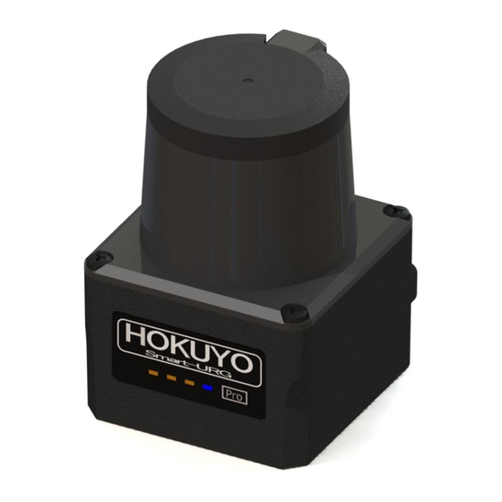
Document No:C-41-02649-2 3.2 Components of UST-30LC and UST-30LC-X01 Figure 3-1 shows the components of UST. Optical window Housing Power supply/IO cable Indicator lamp Ethernet cable Figure 3-1 UST components... - Page 10 Document No:C-41-02649-2 Figure 3-2 shows the scanning range and detection zone origin of the UST, while figure 3-3 shows its detection plane. Detection zone origin 0° Scanning range 270° Figure 3-2 Scanning range and detection zone origin (Top view) Detection plane marking Detection plane Figure 3-3 Detection plane of UST (Back view)
-
Page 11: Operation Principle
Document No:C-41-02649-2 3.3 Operation principle 270° 0° Figure 3-4 Scanning range Figure 3-4 shows the scanning range of the UST. The sensor emits pulsed laser beams which reflect on a rotating mirror forming a fan-like scanning pattern over 270 ° field. Maximum detection range is 30m for white Kent sheet. -
Page 12: Area Configuration
Output 1, 2 and 3 respectively. For UST-30LC, output region 1 to 3 can be configured in both LA mode 1 and LA mode 2.In LA mode 1, maximum 31 set of areas and in LA mode 2, maximum 15 set of areas can be configured. - Page 13 Document No:C-41-02649-2 For independent method, the following shapes (polygon, arc and rectangle) can be set. a)Polygon b)Arc c)Rectangle Figure 3-7 Area configurations (Independent method) For the Dependent method, the following shapes are defined: Straight line, Fan, and Ratio. In the dependent method, output 1 serves as a basis for output 2.
-
Page 14: Area Switching
Document No:C-41-02649-2 3.5 Area switching For UST-30LC, maximum 31 of areas can be configured. For UST-30LC-X01, maximum 15 of areas can be configured. For area switching, input signals are required. Table 3-1, 3-2 below shows the combination of input signal to switch the area. - Page 15 Document No:C-41-02649-2 Table 3-1 Input states and corresponding area number (UST-30LC) LA Mode 1 LA Mode 2 Input1 Input2 Input3 Input4 Input5 Input1 Input2 Input3 Input4 Area Number Laser off Area 1 Area 2 Area 3 Area 4 Area 5...
- Page 16 Document No:C-41-02649-2 Table 3-2 Input states and corresponding area number (UST-30LC-X01) LA Mode 1 LA Mode 2 Area Number Input1 Input2 Input3 Input4 Input1 Input2 Input3 Laser off Area 1 Area 2 Area 3 Area 4 Area 5 Area 6...
-
Page 17: Detection Condition
Document No:C-41-02649-2 3.6 Detection condition In the configured area, if the detectable size (width) is more than the minimum detectable objects, an output signal is displayed (for setting refer to section 3.10). The width of detectable object can be calculated as shown in figure 3-9. -
Page 18: On/Off Delay
Document No:C-41-02649-2 3.7 ON/OFF delay ON delay and OFF delay of the output signal can be set by using Area Designer within the range of 1scan (66ms) to 128 scan (3241ms) (default is 1scan(66ms)) ON delay is the response time changing from OFF state to ON state. OFF delay is the response time changing from ON state to OFF state. - Page 19 Document No:C-41-02649-2 2. Schematic diagram when 2 scan OFF delay setting :Object absent :Object present Output judgment Output judgment Output judgment 1scan (Object absent) 2scan (Object absent) 3scan (Object present) 3. Schematic diagram without ON delay setting :Object absent :Object present Output judgment Output judgment 1scan (Object present)
-
Page 20: Hysteresis Function Of Detection Area
Document No:C-41-02649-2 3.8 Hysteresis function of detection area When a sensor detects an object near the boundary of the detection area, outputs 1 to 3 may oscillate (changing to ON/OFF state) repeatedly. To prevent such oscillation, sensor has a hysteresis function that temporarily increases the area size (Ratio Mode and Two-Step Mode). - Page 21 Document No:C-41-02649-2 When you set the detection area close to a wall, set the hysteresis to the minimum value. If the surface of the wall is within the hysteresis detecting area range, the output will not return to its original state.
-
Page 22: Scan Skip Function
Document No:C-41-02649-2 3.9 Scan skip function When scan skip function is activated, it stops laser emission of the set scan number during rotation. Through sensor setting, it is possible to stop laser emission from 0 scan to 5 scan. Figure 3-14 shows the schematic diagram, when scan skip count “0”is set. -
Page 23: Setting Of Ust
[default] The Synchronize function is available. Area detection and data output type. It is a single echo data output. ●UST-30LC Number of areas 31, Number of Regions 3 LA Mode 1 The Synchronize function cannot be used. ●UST-30LC-X01... - Page 24 Document No:C-41-02649-2 Parameter Description Scan skip count can be set. Select from below setting. Setting Description 0[default] No scan skip. 1 scan skip. Scan skip count 2 scan skip. 3 scan skip. 4 scan skip. 5 scan skip. To prevent mutual interference between the sensors, motor synchronous angle can be set by delaying the motor rotation.
- Page 25 Document No:C-41-02649-2 Parameter Description This mode lowers the detection sensitivity of the sensor. This filter is effective to remove light interference. Select from below setting. Setting Description Low sensitivity mode OFF[default] Low sensitivity mode is not active. Low sensitivity mode is active. Caution: The detection distance is about half of the specifications.
-
Page 26: Output
Document No:C-41-02649-2 3.11 Output The UST has 3 types of outputs as below. 3.11.1 Output 1 to Output 3 Output 1: When the object is detected in the output region 1, output 1 will switch to OFF state. Output 2: When the object is detected in the output region 2, output 2 will switch to OFF state. Output 3: When the object is detected in the output region 3, output 3 will switch to OFF state. -
Page 27: Input
Document No:C-41-02649-2 Scan direction Measurement range Synchronous output Figure 3-16 The timing of synchronous signal OFF duration 24ms Tr = ON Synchronous output Tr = OFF During malfunction, Tr is ON. Figure 3-17 Synchronous output signal 3.12 Input The UST has 2 types of inputs as below. 3.12.1 Input 1 to Input 5 These inputs are used in order to choose detection area. -
Page 28: Indicator Lamp
Document No:C-41-02649-2 3.13 Indicator lamp 4 LED display indicates the UST status. This LED display is located in the front of the UST as shown in Figure 3-18. Table 3-5 shows the description of the LEDs. Power supply display (Blinks during start up, configuration and malfunction state) Output 3 Output 2... -
Page 29: Laser Spot
Document No:C-41-02649-2 3.14 Laser spot The laser spot of the UST is as shown in figure 3-19. The spread of laser spot differs on the front and side of the unit. The size value is for reference only. Front view 280×120mm 500mm Floor surface... -
Page 30: Data Logging
Document No:C-41-02649-2 3.15 Data logging By connecting the UST with the Area Designer software for data logging (the log includes: distance, intensity, output states, recording time), it is possible to record and play of log data. The operating steps are as follows. 3.15.1 Record of log data Follow the steps below for data recording. -
Page 31: Playing Log Data
Document No:C-41-02649-2 3.15.2 Playing log data Follow the steps below for playing log data. ① Click play button as shown in figure 3-23. (Cannot play the log data until measurement display button is OFF) Play log data Measurement display [Ctrl+0] Figure 3-23 Play log data button ②... -
Page 32: Area Rotation Function
Document No:C-41-02649-2 3.16 Area rotation function Area Designer has function to rotate all areas. It can be used when the UST installation is tilted horizontally. Select angle in “Rotate All” as shown in the figure 3-25 and click “Set” button. Select Click Rotated area... -
Page 33: Installation
Document No:C-41-02649-2 4. Installation This chapter describes precautions during sensor installation. The UST can be fixed to a surface using either the back mounting plate or the bottom mounting plate and each plate provided with two screw holes. This mounting plate is used as a frame ground (FG). Mount the sensor on a stable structure. -
Page 34: Mutual Interference
Document No:C-41-02649-2 4.2 Mutual interference Extra precautions are required while using two or more identical UST sensors because pulsed laser signals from identical UST units could lead to false detection.When interference reduction mode is selected, it might be effective to avoid mutual interference. Figures below show the installation method for avoiding mutual interference. - Page 35 Document No:C-41-02649-2 5°or more 5°or more Detection plane Detection plane Figure 4-5 Parallel installation C) Adding shield in between UST By adding a shield in between the UST units, laser beam cannot reach the opposite sensor so this will avoid possible mutual interference Detection plane Detection plane...
-
Page 36: Synchronous Operation
Document No:C-41-02649-2 4.3 Synchronous operation When operating two or more UST units within a short distance mutual interference may occur. To prevent mutual interference between them, the rotation of the USTs can be synchronized. A maximum of 3 UST units can be operated by delaying the rotation by 90 degrees (however, this cannot guarantee 100% prevention of mutual interference, depending upon the installation condition, background condition, etc., of each UST. -
Page 37: Example Of Phase Setting
Document No:C-41-02649-2 4.3.1 Example of phase setting In case of installing multiple units of UST, refer to the figure 4-9 to figure 4-10 for phase setting. a) Parallel installation To prevent mutual interference between 2 units of UST in a parallel installation. Set Master unit phase: 0°... -
Page 38: Wiring
Document No:C-41-02649-2 5. Wiring This chapter describes precaution to take during wiring. 5.1 Precautions During electric wiring make sure that all devices are disconnected from power supply. Switch off all the power supply during wiring. 5.2 Power supply Make sure that power supply is either DC 12V or DC 24V (operation voltage range 10V to 30V) In case rated output voltage exceeds this range, UST could be damaged. -
Page 39: Wire Color And Function
Document No:C-41-02649-2 5.3 Wire color and function 5.3.1 UST-30LC Table 5-1 shows the color of each lead wire, signal name, etc. The function is different in each mode. Table 5-1 Wire color and function (UST-30LC) Color Signal Orange(Red short point 1) -
Page 40: Ust-30Lc-X01
Document No:C-41-02649-2 5.3.2 UST-30LC-X01 Table 5-2, 5-3 shows the color of each lead wire, signal name, etc. The function is different in each mode. Table 5-2 Wire color and function (UST-30LC-X01) Color Signal Orange(Black short point 1) -VIN Orange(Red short point 1) -
Page 41: Input/Output Circuit
Document No:C-41-02649-2 5.4 Input/Output circuit 5.4.1 Input circuit Photo coupler input circuit (cathode COM, Input ON current 4mA) 5.4.2 Output circuit PNP open collector output circuit (maximum DC 30V, 50mA) Figure 5-1 Example of connecting input / output circuit... -
Page 42: Option Cable
Document No:C-41-02649-2 5.5 Option cable Various optional cables are available for UST-30LC-X01. 5.5.1 Power supply and I/O cable Pin assignments for each plug are shown in Figure 5-4 and Table 5-5. Table 5-4 Power supply and I/O option cable Name Type Cable No. - Page 43 Document No:C-41-02649-2 5.5.2 Ethernet cable Pin assignments for each plug are shown in Figure 5-6 and Table 5-7. Table 5-6 Ethernet option cable Name Type Cable No. UZ00148 UST-ENET001 UST Ethernet cable (1m) UST-ENET001 UZ00149 UST-ENET003 UST Ethernet cable (3m) UST-ENET003 UZ00150 UST-ENET005 UST Ethernet cable (5m)
-
Page 44: Setting Of Area Designer
Document No:C-41-02649-2 6. Setting of Area Designer Install the application software (Area Designer) in a supported operating system and connect UST using an Ethernet cable. Area Designer has the following functions: Configuration of detection area Configuration of various UST functions ... -
Page 45: Communication
Document No:C-41-02649-2 7. Communication 7.1 Ethernet setting 7.1.1 Initial value Initial value of IP : 192.168.0.10 Port No. : 10940 7.1.2 Changing IP address It is possible to change and reset the IP address using a specialized application (IP Discovery). For details on installation and operation of IP Discovery, please refer to IP discovery manual. -
Page 46: Inspection And Maintenance
Document No:C-41-02649-2 8. Inspection and maintenance Inspection and maintenance are necessary for safety operation. User must ensure that inspection and maintenance are carried out as specified. Before performing inspection and maintenance, confirm the following items. The machine monitored by the UST is switched OFF ... -
Page 47: Pre-Operation Inspection
Document No:C-41-02649-2 8.1 Pre-operation inspection After configuration is completed, pre-operation inspection test should be performed using a test piece. User should perform this inspection without connecting the sensor to the system. Table 8-1 shows an example of pre-operation inspection items list. Table 8-1 Pre-operation inspection list Condition Check item... -
Page 48: Daily Inspection
Document No:C-41-02649-2 8.3 Daily inspection Below Table 8-3 shows an example of the items that should be checked during daily inspection. Table 8-3 Daily inspection list Condition Check item Remark UST is correctly mounted at the intended location and screws are firmly fastened All the wirings are correctly connected When the test piece is placed in the detection area Output 1 to 3 switch from ON state to OFF state... -
Page 49: Periodical Inspection
Document No:C-41-02649-2 8.4 Periodical inspection Periodical inspection should be performed to ensure the detection capability of the UST. Table 8-4 below shows an example list of periodical inspection items. It is recommended to perform this inspection in six months interval. This inspection should be performed together with daily inspection. Table 8-4 Periodical inspection list Condition Check item... -
Page 50: Cleaning The Optical Window
Document No:C-41-02649-2 8.5 Cleaning the optical window Dust covering the optical windows affects the detection capability of the UST. When you install UST in the dusty environment, regular cleaning of the optical window is needed. According to the contamination situation follow the below method: ... -
Page 51: Troubleshooting
Document No:C-41-02649-2 9. Troubleshooting While using this sensor, if problem occurs, then refer to the following table. Table 9-1 Troubleshooting list Situation Possible reason Solution suggestion Power supply is Make sure power supply is ON. OFF /Over voltage/ Voltage is within the specification. Under voltage UST is not operating Cable is damaged... - Page 52 Document No:C-41-02649-2 Hysteresis setting Reconfirm the hysteresis setting. For repairing the UST, please contact our nearest distributor or sales representative. Do not repair or disassemble the UST. Such modifications will void the warranty.
-
Page 53: Specification
Note: Area Detection 1 to 3 are swiched OFF during malfunction state. Photo-coupler, common cathode, power supply is 4mA when input is ON. 5 INPUT: Inputs Input1, Input2, Input3, Input4, Input5/Synchronization input(UST-30LC) 4 INPUT: Input1, Input2, Input3, Input4/Synchronization input(UST-30LC-X01) OFF:66msec to 3241msec... - Page 54 Document No:C-41-02649-2 LX mode・・・ Power supply LED display (blue): Blinks during start up and malfunction state. LA mode・・・ Blue LED: ON during normal operation, blink during the start up, configuration LED display and malfunction state. Orange LED 1: Output 1 ON during object detection. Orange LED 2: Output 2 ON during object detection.
- Page 55 *5: Initial setting is synchronization master. When using synchronization operation, refer to section 4.3 for details about synchronization wiring. Synchronization slave setting is possible using Area Designer. *6: The protective structure of Ethernet and Power connector is not IP 67 (UST-30LC only). *7: The startup temperature is -10°C to +50°C.
-
Page 56: Applicable Directives And Standards
Document No:C-41-02649-2 11. Applicable directives and standards Table 11-1 shows the conformant EU directives and EN standards Table 11-1 Directives and Standards Directives/Standard Details EMC Directives Directives RoHS Directives (EMI) EN61326-1:2013 EN55011:2009 + A1:2010 (EMS) EN61326-1:2013 EMC Directives EN61000-4-2:2009 EN61000-4-3:2006 + A1:2008 + A2:2010 EN61000-4-4:2012 EN61000-4-6:2014 EN61000-4-8:2010... -
Page 57: Package Contents
Document No:C-41-02649-2 12. Package contents The following items are included in the package: UST-30LC or UST-30LC-X01 ×1 User’s Manual ×1... -
Page 58: External Dimensions
Document No:C-41-02649-2 13. External Dimensions E th er ne t ca bl e ( T he m in im um ca bl e be nd i ng r ad iu s is 20 mm ) D et ec ti on a ng l e 27 0゚ P ow er /O ut pu t C ab le (... -
Page 59: Revision History
Document No:C-41-02649-2 14. Revision history Document No. Amended No. Revision date Details March 2021 First Release - - C-41-02649-1 RS-01738 October 2021 Comment added P.39 P.41 P.42 P.50 C-41-02649-2 RS-02050 July 2023 Added the startup temperature conditions P.53 P.54 ★The contents described in this document are based on the information as of March 2021.The external dimensions;...
Need help?
Do you have a question about the UST-30LC and is the answer not in the manual?
Questions and answers