Table of Contents
Advertisement
Quick Links
Advertisement
Table of Contents

Related Manuals for HOKUYO AUTOMATIC UXM-30LAH-EWA


Summary of Contents for HOKUYO AUTOMATIC UXM-30LAH-EWA
- Page 1 Document No: C-41-02567 Scanning Laser Range Finder UXM-30LAH-EWA User’s Manual...
-
Page 2: Table Of Contents
2.4 Wiring ..............................6 2.5 Configuration ............................6 2.6 Inspection and maintenance ....................... 6 3. Product overview ............................7 3.1 Features of UXM-30LAH-EWA ......................7 3.2 UXM-30LAH-EWA components ......................8 3.3 Operation principle ........................... 10 3.4 Area configuration ..........................12 3.5 Area switching ............................ - Page 3 Document No: C-41-02567 5.1 Caution for installation ........................26 5.2 Optical axis adjustment ........................27 5.3 Light interference ..........................27 5.4 Mutual intreference ..........................28 5.5 Synchronous operation ........................29 5.5.1 Example of phase setting........................ 30 6. Wiring ................................. 32 6.1 Precautions ............................
-
Page 4: Introduction
1. Introduction This user’s manual is designed with the purpose of providing guidelines and instructions for the machine user or system designer while operating, installing, wiring and servicing the UXM-30LAH-EWA sensor. 1.1 About this document/manual The UXM’s features, installation and handling method are described in this document. -
Page 5: Cautions
Document No: C-41-02567 1.4 Cautions The UXM has been shipped upon strict quality control. If you find any defect in the product, contact the nearest distributor or sales representative. Hokuyo cannot be held responsible for damages or failure due to misuse of the product. ... -
Page 6: Safety Precautions
Document No: C-41-02567 2. Safety precautions Make sure to read the following safety precautions for the correct use and operation of the UXM. 2.1 General precautions The UXM uses laser radiation for detecting objects within configured area. Perform pre-operation tests in order to verify the performance of the UXM. ... -
Page 7: Wiring
Document No: C-41-02567 that lie behind the obstacle. Increasing the response time will also increase the stability of the UXM. However, this will reduce the detection capability towards moving objects. User must perform pre-operation tests before using this function. 2.4 Wiring ... -
Page 8: Product Overview
UXM emits pulsed laser beam which reflect on a rotating mirror within the configured area. When the emitted laser beams are reflected back from an object its distance is measured. This chapter describes the features and properties of the UXM-30LAH-EWA. 3.1 Features of UXM-30LAH-EWA ... -
Page 9: Uxm-30Lah-Ewa Components
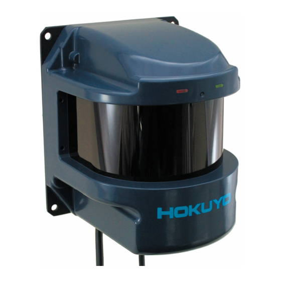
Document No: C-41-02567 3.2 UXM-30LAH-EWA components Figure 3-1 shows the components of UXM-30LAH-EWA Indicator lamp Optical window Interface connector Cable connector Figure 3-1 UXM-30LAH-EWA components Figure 3-2 shows the scanning range and detection zone origin of the UXM, while figure 3-3 shows its... - Page 10 Document No: C-41-02567 Scanning range Detection zone origin 95° 63.5mm 190° Figure 3-2 Scanning range and detection zone origin (Top view) Detection plane Detection zone origin Figure 3-3 Detection plane of UXM (Front view)
-
Page 11: Operation Principle
Document No: C-41-02567 3.3 Operation principle Output region 1 Output region 2 Output region 3 190° 0° Figure 3-4 Scanning range Figure 3-4 shows the scanning range of the UXM. The sensor emits pulsed laser beam which reflect on a rotating mirror forming a fan-like scanning pattern over 190 °... - Page 12 Document No: C-41-02567 The operation principle of TOF is shown in schematic diagram (Figure 3-5) below Figure 3-5 TOF operation principle...
-
Page 13: Area Configuration
Document No: C-41-02567 3.4 Area configuration The detection area of the UXM consist the output regions 1, 2 and 3 respectively. Output 1 to Output 3 can be configured by using the Area Designer application software through an Ethernet cable. Area configuration methods can be Independent and Dependent. -
Page 14: Area Switching
Document No: C-41-02567 For details on area configuration methods, refer to the Area Designer sensor configuration tool Instruction manual. When the sensor detects an object in the configured output region 1 to output region 3, the corresponding outputs signals are switched to OFF state and the corresponding LEDs are also lit. ... -
Page 15: Detection Condition
Document No: C-41-02567 3.6 Detection condition In the configured area, if the detectable size (width) is more than the minimum detectable objects an output signal is displayed (for setting refer to section 3.9).The width of detectable object can be calculated as shown in figure 3-8. -
Page 16: On Delay/Off Delay
Document No: C-41-02567 3.7 ON /OFF delay ON delay and OFF delay of the output signal can be set by using Area Designer within the range of 50ms to 6400ms with an interval of 50ms. (Default is 50ms) ON delay is the response time changing from ON state to OFF state after detecting the object. OFF delay is the response time changing from OFF state to ON state while not detecting the object. - Page 17 Document No: C-41-02567 2. Example of schematic diagram when 2 scan OFF delay setting : Object absent : Object present Output judgment Output judgment Output judgment 1scan (Object absent) 2scan (Object absent) 3scan (Object present) 3. Example of schematic diagram without ON delay setting : Object absent : Object present Output judgment...
-
Page 18: Hysteresis Of Detection Area
Document No: C-41-02567 3.8 Hysteresis of detection area When a sensor detects an object near the boundary of the detection area, outputs 1 to 3 may oscillate (Changing of ON/OFF state) repeatedly. To prevent such oscillation, sensor has a hysteresis function that temporarily increases the area size. - Page 19 Document No: C-41-02567 When you set the detection area close to a wall, set the hysteresis to the minimum value. If the surface of the wall is within the hysteresis detecting area range, then the output will not return to its original state.
-
Page 20: Setting Of Uxm
Document No: C-41-02567 3.9 Setting of UXM Setting of operating parameter of UXM by Area Designer. Table 3-2 describes UXM’s parameters and settings. Table 3-2 Parameter settings Parameter Description To prevent mutual interference between the sensors, motor synchronize angle can be set by delaying the rotation. For details on synchronization operation, refer to chapter 5.5 Motor sync angle Setting... - Page 21 Document No: C-41-02567 Table 3-2 Parameter settings Parameter Description Sensitivity filter is used to remove the objects with low reflectivity. This filter is effective to remove light interference and rain. Select from below setting. Setting Reference value while using sensitivity filter Filter not used.
-
Page 22: Output
Document No: C-41-02567 3.10 Output The UXM has 4 types of outputs as below. 3.10.1 Detection Output 1 to Output 3 Detection Output 1: When the object is detected in the output region 1, ON (Low level) state will switch to OFF (High level) state. -
Page 23: Synchronous Master Output
Document No: C-41-02567 3.10.4 Synchronization master output It is a reference clock signal for synchronizing motor rotation of each sensor. 50ms of cycles and an output ON period (Low level) output the clock signal used as 12.5ms (Duty 25%).Output starts immediately after the power ON, and an output is continued even in the malfunction state. -
Page 24: Indicator Lamp
Document No: C-41-02567 3.12 Indicator lamp 2 LED display indicates the UXM status. This LED display is located in the front of the UXM as shown in figure 3-14. Table 3-3 shows the description of the LEDs. Area determination LED lamp Power supply, Operation LED lamp (Orange LED) (Green LED) -
Page 25: Application Examples Of The Uxm
Document No: C-41-02567 4. Application examples of the UXM In this chapter will explain giving some application examples where the UXM can be used. Before installing, user has to decide the main purpose for using the UXM. Next, decide the suitable installation place as well as required detection area size, etc. -
Page 26: Access Protection
Document No: C-41-02567 4.2 Access protection Access protection Security monitoring of a building and premises (Vehicles, person etc.) Building Premises Maximum 80m Figure 4-3 Example of access protection... -
Page 27: Installation
5-1, the spread of the beam differs from front to side. Front view 500mm 400×110mm Floor surface (Reference value) Side view 110×400mm (Reference value) Figure 5-1 Spread of beam of UXM-30LAH-EWA Table 5-1 Beam size (Reference value) Beam size(Reference value)(mm) Distance (m) Front view Side view 60×30 30×60 110×40 40×110... -
Page 28: Optical Axis Adjustment
Document No: C-41-02567 5.2 Optical axis adjustment Angular tolerance with respect to structure axis is ±0.2° in the horizontal plane and ±0.5°in the vertical plane. (Figure 5-2) Use the adjustment mechanism for precisely adjusting the detection plane. Detection plane can be checked by Optical-Axis Checker (Model: UES-930, Sold separately) Horizontal angle ±0.2°... -
Page 29: Mutual Intreference
Document No: C-41-02567 5.4 Mutual interference Extra precautions are required while using two or more identical UXM sensors because pulsed laser signals from identical UXM units could lead to false detection. Figures below show the installation method for avoiding mutual interference. a) Changing the height of installation Displace the installation position up and down;... -
Page 30: Synchronous Operation
Document No: C-41-02567 5° or more 5° or more Detection plane Detection plane Figure 5-7 Parallel installation c) Adding shield in between UXM By adding a shield in between the UXM units, laser beam cannot reach the opposite sensor so this will avoid possible mutual interference. -
Page 31: Example Of Phase Setting
Document No: C-41-02567 UXM-30LAH-EWA Input COM + (Slave) Synchronize Input UXM-30LAH-EWA Input COM + (Slave) Synchronize Input UXM-30LAH-EWA Input COM + (Slave) Synchronize Input DC12V/ 24V Input COM + UXM-30LAH-EWA Power supply Synchronize Input (Master) Synchronize master output Output COM- Figure 5-10 Example of synchronization wiring (In case of 4 UXM) 5.5.1 Example of phase setting... - Page 32 Document No: C-41-02567 b) Opposite facing installation Slave phase:180° To prevent mutual interference between 2 units of UXM opposite facing installation. Set Master phase: 0° Slave phase: 180° Master phase:0° Figure 5-12 Example of opposite facing installation c) Installing 4 units of UXM To prevent mutual interference between 4 units of UXM installed facing 4 different directions.
-
Page 33: Wiring
Document No: C-41-02567 6. Wiring This chapter describes precaution when wiring the UXM. 6.1 Precautions During electric wiring, make sure that all devices are disconnected from power supply. Switch off all the power supply during wiring. 6.2 Power supply Make sure that power supply is either DC 12V or DC 24V (operation voltage range 10V to 30V.) In case rated output voltage exceeds this range, UXM could be damaged. -
Page 34: Wire Colour And Function
Document No: C-41-02567 6.3 Wire color and function Table 6-1 shows the color of each lead wire, signal name, function, etc. Flying lead cable of length 2 m with 16 shields. Table 6-1 Wire color and function Color Signal Description Function Brown +VIN... -
Page 35: Input/Output Circuit
Document No: C-41-02567 6.4 Input/Output circuit 6.4.1 Input circuit Photo coupler input circuit (anode COM, Input ON current 2mA, OFF current 0.5mA or less) 6.4.2 Output circuit NPN Open output collector circuit Table 6-2 Output circuit specification Item Specification Maximum output current 50mA Maximum applied voltage Output residual voltage... -
Page 36: Interface Connector
Document No: C-41-02567 6.5 Interface connector Sensor setting and measurement data can be obtained by Ethernet connection. User should prepare Ethernet cable which connects a sensor with PC. CAT5 (Standard twisted-pair cable) is used which connects between the Ethernet connecting plug (a straight type plug or L type plug) and the RJ-45 modular plug. Pin assignment of each plug is shown in table 6-3 and table 6-4. -
Page 37: Setting Of Area Designer
Document No: C-41-02567 7. Setting of Area Designer Install the application software (Area Designer) in a supported operating system and connect UXM using an Ethernet cable. (For details refer to section 6.5). Area Designer has the following functions: Configuration of detection area ... - Page 38 Document No: C-41-02567 Operation is not guarantee even if the system requirements are fulfilled. Read thoroughly the Instruction manual of Area Designer for configuring UXM. Instruction manual can be loaded from the help menu of Area Designer.
-
Page 39: Communication
LEDs, release the switch. After initialization process is completed, return the cap to its original position. For details on changing the IP address, refer to the manual of IP change tool. Ethernet connector Ventilation window Input/Output cable IP initialization switch Figure 8-1 UXM-30LAH-EWA (Bottom part) -
Page 40: Communication Protocol
Document No: C-41-02567 8.2 Communication protocol For details on the communication protocol, refer to the UXM series LA type Communication specification (C-42-04041). 8.3 Error code table The cause of an error can be obtained from STAT line of the “II” Command response, in the SCIP communication protocol. -
Page 41: Inspection And Maintenance
Document No: C-41-02567 9. Inspection and maintenance Inspection and maintenance are necessary for safety operation. User must ensure that inspection and maintenance are carried out as specified. Before performing inspection and maintenance, confirm the following items. The machine monitored by the UXM is switched OFF. ... -
Page 42: Pre-Operation Inspection
Document No: C-41-02567 9.1 Pre-operation inspection After configuration is completed, pre-operation inspection test should be performed using a test piece. User should perform this inspection without connecting the sensor to the system. Table 9-1 shows an example of pre-operation inspection items list. Table 9-1 Pre-operation inspection list Condition Check item... -
Page 43: Daily Inspection
Document No: C-41-02567 9.3 Daily inspection Below table 9-3 shows an example of the items that should be checked during daily inspection. Table 9-3 Daily inspection list Condition Check item Remark UXM is correctly mounted at the intended location and screws are firmly fastened All the wirings are correctly connected When the test piece is placed in the detection area... -
Page 44: Periodical Inspection
Document No: C-41-02567 9.4 Periodical inspection Periodical inspection should be performed to ensure the detection capability of the UXM. Table 9-4 below shows an example list of periodical inspection items. It is recommended to perform this inspection in six months interval. This inspection should be performed together with daily inspection. Table 9-4 Periodical inspection list Condition Check item... -
Page 45: Cleaning The Optical Window
Document No: C-41-02567 9.5 Cleaning the optical window Dust covering the optical windows affects the detection capability of the UXM. When you install UXM in the dusty environment, regular cleaning of the optical window is needed. According to the contamination situation follow the below method: ... -
Page 46: Trobleshooting
Document No: C-41-02567 10. Troubleshooting While using this sensor, if problem occurs, then refer to the following table. Table 10-1 Troubleshooting list Situation Possible reason Solution suggestion Power supply is Make sure power supply is ON OFF /Over voltage/ Voltage is within the specification UXM is not Under voltage... - Page 47 Document No: C-41-02567 For repairing the UXM, please contact our nearest distributor or sales representative. Do not repair or disassemble the UXM. Such modifications will void the warranty.
-
Page 48: Specification
Document No: C-41-02567 11. Specification Table 11-1 Specification of UXM-30LAH-EWA Scanning laser range finder Product name UXM-30LAH-EWA Model Supply voltage DC12V/DC24V (Operating range DC10V to DC30V, ripple within ±10%) Steady current : 300mA or less Start current: approx.750mA (when using DC24V) Supply current Steady current : 600mA or less Start current: approx.1500mA (when using DC12V) - Page 49 Document No: C-41-02567 Green LED : Power supply and normal operation Indicator LED Orange LED : Area determination (About indicator lamp refer to section 3.12) -10°C to +50°C below 85%RH (Without dew, frost) Ambient temperature, -30°C to +50°C below 85%RH (When heater in use) humidity (Without dew, frost) Measured distance will be shorter than the actual distance under the influence of...
-
Page 50: Applicable Directives And Standards
Document No: C-41-02567 12. Applicable directives and standards Table 12-1 shows the conformant EU directives and EN standards Table 12-1 Directives and Standards Directives/Standard Details EMC Directives Directives RoHS Directives (EMI) EN61326-1:2013 EN55011:2009 + A1:2010 (EMS) EN61326-1:2013 EMC Directives EN61000-4-2:2009 EN61000-4-3:2006 + A1:2008 + A2:2010 EN61000-4-4:2012 EN61000-4-6:2009... -
Page 51: Package Contents
Document No: C-41-02567 13. Package contents The following items are included in the package: UXM-30LAH-EWA ×1 User’s manual ×1... -
Page 52: External Dimension
Document No: C-41-02567 14. External dimension Figure 14-1 External dimension of UXM-30LAH-EWA... -
Page 53: Revision History
Document No: C-41-02567 15. Revision history Document No. Amended No. Revision date Details June 2017 First Release... -
Page 54: Represntative Contacts
Tel: +81-6-6947-6333 Fax: +81-6-6947-6350 E-mail: overseas-sales@hokuyo-aut.co.jp URL: http://www.hokuyo-aut.jp Europe Hokuyo Automatic Co., Ltd. Amsterdam Branch Prof. J.H. Bavincklaan 2, 1183 AT Amstelveen, The Netherlands Tel: +31 20 240 01 10 E-mail: amsterdam.branch@hokuyo-aut.co.jp URL: http://www.hokuyo-aut.jp North America Hokuyo Automatic USA Corporation...
Need help?
Do you have a question about the UXM-30LAH-EWA and is the answer not in the manual?
Questions and answers