Table of Contents
Advertisement
Quick Links
△
×
Approved
Checked
MEASURING
DISTANCE TYPE
S S S S canning
canning laser range
canning
canning
laser range
laser range
laser range
finder
finder
finder
finder
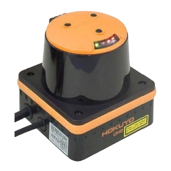
UHG-08LX
INSTRUCTION
MANUAL
Drawn
Designed
Mori
S S S S canning
canning laser range finder
canning
canning
Title
UHG-08LX Instruction Manual
Drawing
No.
Date:2008.1.20
社
laser range finder
laser range finder
laser range finder
1/8
Advertisement
Table of Contents

Subscribe to Our Youtube Channel
Related Manuals for HOKUYO AUTOMATIC UHG-08LX


Summary of Contents for HOKUYO AUTOMATIC UHG-08LX
- Page 1 UHG-08LX INSTRUCTION MANUAL △ × 社 S S S S canning canning laser range finder laser range finder canning canning laser range finder laser range finder Approved Checked Drawn Designed Title UHG-08LX Instruction Manual Mori Drawing...
- Page 2 - NOTICE NOTICE – – – – NOTICE NOTICE ○Please keep this instruction manual on the side of operator and maintenance person. ○Be sure to read this instruction manual and relative documents carefully before installation, operation and maintenance. Operate correctly in accordance with the directions for use, information for safety and handling method of this device.
- Page 3 1. Outline UHG-08LX is a laser sensor for area scanning. The sensor’s light source is infrared laser of wavelength 785nm. Scan area is 240°semicircle with pitch angle 0.36°. Sensor outputs the distance measured at every point. The sensor’s maximum measurement is 8000mm with white Kent sheet of 250×250 mm. Laser beam divergence is 80mm at 8m.
- Page 4 3.Specifications Product Name Laser sensor for area scanning (Research Prototype) Model UHG-08LX Light source Semiconductor laser diode (λ=785nm), Laser safety Class 1 (FDA) Power source 12V DC ±10% Current consumption 300mA or less (Rush current 800mA) Detection distance 50mm ~ 8000mm* (White sheet of 250mm width or more) (Refer the data provided with the sensor for the max.
- Page 5 4. Quality reference value Vibration resistance 19.6m/s 10Hz ~ 150Hz in 2 minutes sweep, 0.5 hours at the time of use each for X, Y and Z direction Impact resistance 49 m/s , 10 times each for X, Y and Z direction at the time of use Turn corner speed 360 deg/s...
- Page 6 6. Control Signal (1) Synchronous output Synchronous output will supply one pulse/scan for 10msec (Figure 2). Scan Direction Approx. 50msec Scan Range Approx. 1msec Synchronous output time Approx. 10msec Figure 2 約 10ms 56ms Synchronous output (2) Malfunction Output All the outputs will be turned off during malfunction. Confirm the malfunction by viewing the malfunction LED.
- Page 7 7. Output Circuit: Internal CN1 Power Source +POWER IN (+VIN) -POWER IN(-VIN) Internal Control OUT (1POINT) Circuit (Open collector NPN) Transistor Rated Value 50V, 30mA CN2 TYPEA 8. Notice: Supply voltage is DC 12Volts. Sensor will damage if high voltage is supplied. The maximum data step is 683 points.
- Page 8 9.External Design and Sensor Dimension CAUTION CAUTION CAUTION CAUTION Use of controls, adjustments or performance of procedures other than those specified in this manual may result in hazardous radiation exposure. Laser radiation signal light Laser radiation area ° Laser radiating point Laser radiating point Drawing S S S S canning...
Need help?
Do you have a question about the UHG-08LX and is the answer not in the manual?
Questions and answers