
Related Manuals for CONTROL SOLUTIONS LogTag VFC400-WiFi


Summary of Contents for CONTROL SOLUTIONS LogTag VFC400-WiFi
- Page 1 Control Solutions VFC400-WiFi Wireless Vaccine temperature monitoring Data Logger Product User Guide Document Release Version: 1.3 Published 29. May 2019 Copyright © Control Solutions, 2018-2019 www.vfcdataloggers.com...
-
Page 2: Table Of Contents
VFC400-WiFi User Guide Contents Safety Information Liability Battery Life Disclaimer Typographical Conventions Introduction Features Case Buttons Display and LED Sensors Communication Power Supply What You Need Required Items Optional Items Preparing a VFC400-WiFi for first use In the office On-site Inserting the Batteries Configuring the VFC400-WiFi for logging Finalizing the configuration... - Page 3 VFC400-WiFi User Guide Interpreting the Data Data Evaluation - Report Data Evaluation - Data List Data Evaluation - Day Summary Resetting the Logger Hibernating a VFC400-WiFi Airplane Mode Replacing the Batteries Technical Specifications...
-
Page 4: Safety Information
VFC400-WiFi. in this font Text in this font refers to option settings, dialogue boxes or actions to be taken in Control Solutions VTMC. Text in this font describes features of the product. WiFi, cloud connection, airplane, power and low battery symbols may not be shown on all screens. -
Page 5: Introduction
… an alarm trigger summary of up to the last 30 days (today and 29 days previous) … the wireless and cloud connection states At set intervals the VFC400-WiFi uploads these data to your Control Solutions Online cloud account, where they can be viewed, analyzed and shared with others, or downloaded for further analysis. -
Page 6: Case
1. Via the built-in Micro USB socket and connection to a PC 2. Via WiFi connection to Control Solutions Online The unit is configured via a PC using Control Solutions VTMC. Power Supply The same USB socket that is used for communication is also used for providing power to the VFC400-WiFi, using an external 5V USB power supply. -
Page 7: What You Need
ST100 series for configuration - a PC running Windows 7 or later and Control Solutions VTMC version 3 installed a 5V/5W USB power supply to power the unit permanently via the USB socket... -
Page 8: Preparing A Vfc400-Wifi For First Use
These steps are completed in your office, using a PC connected to the internet. install the backup batteries into the unit download and install the latest version of Control Solutions VTMC 3. You can do this from the Control Solutions, Inc. Software Download page... -
Page 9: Inserting The Batteries
Preparing a VFC400-WiFi for first use VFC400-WiFi User Guide Inserting the Batteries The VFC400-WiFi operates with two AAA backup batteries. 1. Remove the screw from the rear compartment lid. 2. Remove the lid, exposing the battery compartment. 3. Insert the AAA batteries in the correct orientation, as shown. The polarity is marked inside the battery compartment. -
Page 10: Configuring The Vfc400-Wifi For Logging
WiFi network connecting to your cloud account This is done using Control Solutions VTMC software, which can also be used for downloading and analyzing ® data. Control Solutions VTMC includes the LogTag Online Connection Wizard, which will allow you to set wireless and network settings and register the VFC400-WiFi against your Control Solutions Online account. - Page 11 Preparing a VFC400-WiFi for first use VFC400-WiFi User Guide VFC400-WiFi Start Options During configuration with Control Solutions VTMC you can decide when the VFC400-WiFi starts taking temperature readings: Push button start The logger will start taking temperature readings as soon as you have pressed the...
- Page 12 Preparing a VFC400-WiFi for first use VFC400-WiFi User Guide the upper alarm is triggered when the temperature is 10.0 °C or above for an accumulative time of 10 hours. the lower alarm is triggered when the temperature is -0.5 °C or below continuously for 1 hour. Once an alarm has triggered, the alarm indicator ( ) remains shown until the unit is reconfigured.
- Page 13 For detailed information about each parameter please read the section about Configuring a LogTag for logging in Control Solutions VTMC’s User Guide or press F1 for help. These settings only apply to the files generated when plugging the VFC400-WiFi directly into a PC.
- Page 14 /CLEAR/STOP For detailed information about each parameter please read the section about Configuring a LogTag for logging in Control Solutions VTMC’s User Guide or press F1 for help. Wireless and Network Connection Settings The VFC400-WiFi's wireless connection parameters are set up on the WiFi Settings tab.
-
Page 15: Finalizing The Configuration
Online Connection Wizard is a separate program that registers the VFC400-WiFi against your account enables you to create an account with Control Solutions Online (or sign in if you already have an account) allows configuration of wireless and network parameters of your VFC400-WiFi ®... - Page 16 Preparing a VFC400-WiFi for first use VFC400-WiFi User Guide After successful completion of the wireless network test, the Wizard establishes a connection between the VFC400-WiFi ® and the LogTag Online cloud server. When completed successfully, the screen on the right shows. Please refer to the section about Troubleshooting (on page 22) for reasons why the cloud server connection can fail.
-
Page 17: Adding The Sensor And The Power Supply
Preparing a VFC400-WiFi for first use VFC400-WiFi User Guide Adding the Sensor and the Power Supply Before the VFC400-WiFi can record temperature data you will need to connect an external sensor. The VFC400-WiFi accepts any ST100 sensor. Plug the sensor into the socket located at the bottom of the device, as shown below. -
Page 18: Wireless Connectivity
The VFC400-WiFi is designed to upload real time data to the LogTag Online cloud application. To do this, the logger must be connected to a wireless network (WLAN) and be able to connect to Control Solutions's cloud service on the internet. -
Page 19: Wireless And Cloud Symbols
Wireless Connectivity VFC400-WiFi User Guide If a logger is scheduled to take a temperature reading and also upload readings to the server at the same time, the temperature reading will always be taken first before the upload starts. If the logger is powered via the AAA batteries The upload to the server takes place every log interval, or multiple thereof, but no sooner than every 60 minutes. -
Page 20: Testing Your Wireless And Network Connection
Wireless Connectivity VFC400-WiFi User Guide Testing your wireless and network connection ® You can verify that uploading data to the LogTag Online cloud server is working by initiating a Connection Test directly from the VFC400-WiFi. During the connection test the logger will ... - Page 21 Wireless Connectivity VFC400-WiFi User Guide The VFC400-WiFi has successfully established a connection ® to the LogTag Online cloud server (Cloud symbol shows a tick). ® The VFC400-WiFi is now exchanging data with LogTag Online, indicated by an arrow inside the cloud symbol ( ). The arrow may turn on and off repeatedly during the data exchange.
-
Page 22: Troubleshooting
Wireless Connectivity VFC400-WiFi User Guide Troubleshooting ® To successfully upload data to LogTag Online, your VFC400-WiFi needs to be connected to your wireless ® network and be able to access the LogTag Online cloud server. It also needs to be registered to your team's account and must be attached to a location. - Page 23 Wireless Connectivity VFC400-WiFi User Guide either of these access methods. If you continue to get this error, please discuss this further with your network administrator. The VFC400-WiFi has successfully connected to the wireless network and is in ® the process of connecting to the LogTag Online cloud server.
-
Page 24: Display Overview
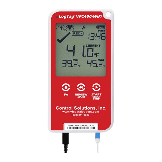
Display Overview VFC400-WiFi User Guide Display Overview Following picture shows the display with all segments turned on. Day Alarm Markers One rows of 7 markers, named Today ( ) to Day -6 ( ). A marker is on, if an alarm event occurred on that day. Week Alarm Markers One row of 4 markers, named last week ( ) to 4 weeks ago (... - Page 25 If the symbol is shown, the VFC400-WiFi is recording temperatures at the sample interval defined during configuration with Control Solutions VTMC. is shown together with the word , the product is recording, but the recorded values are not PAUSED taken into account when calculating alarm events and durations.
-
Page 26: Powering The Vfc400-Wifi
Powering the VFC400-WiFi VFC400-WiFi User Guide Powering the VFC400-WiFi The VFC400-WiFi is designed to be supplied via its USB socket from a commercially available 5V USB power supply (5W). When supplied externally, the power symbol shows on the display: Some low-quality USB power supplies are unable to deliver sufficiently stable power to the VFC400- WiFi. -
Page 27: Low Power Operation
Online … the audible alarm will sound only once, then be silent … the display turns off after 30 seconds of inactivity, regardless of the setting made in Control Solutions VTMC. … reviewing the data is not possible (however a mark will still be placed if the review button is pressed) …... -
Page 28: Audible Alarm
Each time the logger is configured with Control Solutions VTMC the display clock value is set to the PC's current local time (or timezone). -
Page 29: Starting The Logger
The power symbol is shown when the unit is connected to a USB power supply. WiFi and cloud connection symbols are also shown with a tick, if the VFC400-WiFi successfully connected to the wireless network directly after configuration with Control Solutions VTMC. Press the button. -
Page 30: Push Button Start With Start Delay
The WiFi connection symbol is shown with a tick, if the VFC400-WiFi successfully connected to the wireless network directly after configuration with Control Solutions VTMC. As with a regular push button start without delay, the VFC400-WiFi will perform a Connection Test as soon as the recording has started. -
Page 31: During Recording
During Recording VFC400-WiFi User Guide During Recording During normal operation the display shows the most recently recorded temperature. This temperature is updated at the same rate as the logging interval. The current time is also displayed (in 24 hour format). A tick symbol is shown as long as no alarm event has occurred. - Page 32 During Recording VFC400-WiFi User Guide Day Alarm Matrix Display while recording During normal recording, symbols marked with are shown if an alarm occurred on that day. Today Day -1 ...
-
Page 33: Marking A Reading With An Inspection Mark
Online will show an AM or PM inspection, depending on the time of day the inspection took place. Clearing an Alarm During configuration with Control Solutions VTMC you can allow a user to clear an alarm on the display. This is a useful function for an inspector, so repeated alarms can be recognized easier. -
Page 34: Paused Readings
The option is set in the Advanced Settings tab during configuration with Control Solutions VTMC and is expressed in number of readings after the last button press. Paused readings are specially marked in the graph and data listings. How long is displayed depends on when between readings you press the button. - Page 35 During Recording VFC400-WiFi User Guide If the sensor was disconnected for a complete day, the minimum and maximum statistics for that day will show on the display and --.- in the list.
-
Page 36: Power Save
You will be able to see on the PDF and in the summary in Control Solutions VTMC when the min/max values were cleared, but you will not be able to review previous min/max values on screen once they have been... -
Page 37: Reviewing Day Statistics On The Display
Reviewing Day Statistics on the Display VFC400-WiFi User Guide Reviewing Day Statistics on the Display The review of the day statistics history is accessed by pressing the button REVIEW /MARK You can review the data regardless of whether the logger is still logging data, or has already been stopped. Following are some sample display screens you might see during a statistics review. - Page 38 Reviewing Day Statistics on the Display VFC400-WiFi User Guide Pressing the button now displays yesterday’s minimum statistic: flashes, as we are still looking at yesterday's data. Yesterday, no temperature values were recorded below the lower alarm threshold. The alarm for the day was generated by the upper alarm, not by the lower alarm, so a is displayed in the minimum statistics.
- Page 39 Reviewing Day Statistics on the Display VFC400-WiFi User Guide Data from 6 days ago After pressing the button for a few times (skipping days -3 to -5) the maximum statistic from six days ago is displayed: flashes to indicate that the data being displayed are from seven days ago.
- Page 40 Reviewing Day Statistics on the Display VFC400-WiFi User Guide Day Alarm Matrix Display while reviewing During review, symbols marked with are shown to indicate for which day review data are being displayed on screen. Today ...
-
Page 41: Stopping The Vfc400-Wifi
Stopping the VFC400-WiFi VFC400-WiFi User Guide Stopping the VFC400-WiFi You can configure a VFC400-WiFi so it can be stopped with the button. This feature is START /CLEAR/STOP useful when you take the logger out of a shipment and don’t want to falsify the statistics with readings taken after the shipment completion. -
Page 42: Plugging The Vfc400-Wifi Into A Usb Port
These drivers will not be installed if the VFC400-WiFi does not generate files. 3. USB Input Device (HID) Driver This device is used for communication to Control Solutions VTMC and its driver will always be installed, even if Control Solutions VTMC is not present on the computer. 4. -
Page 43: Accessing The Files
PDF, CSV or LTD files. For PDF files you need Adobe Acrobat Reader or a similar PDF viewer. To open the LTD file you need to install the free Control Solutions VTMC software. CSV files can be opened with a text editor, or imported into a spreadsheet program such as ®... - Page 44 Interpreting the Data VFC400-WiFi User Guide Interpreting the Data Data Evaluation - Report Alarm Status ✖ This shows at a glance if the VFC400-WiFi recorded alarm conditions during the trip (showing a red ) or if no ✔ alarms were recorded (green File Information This section shows general information about the PDF file, such as generation time, date and time formats and the file name, which is compiled from information about the data it contains:...
- Page 45 Interpreting the Data VFC400-WiFi User Guide Recorded Data Information This block contains information about the data recorded during the trip. It shows the time covered by the recording and statistical data of the trip. You can see the conditions for which each alarm was to be triggered, and how often such a condition occured.
- Page 46 Interpreting the Data VFC400-WiFi User Guide Data Evaluation - Data List File Information The information from the report page is repeated here. Recorded Data list The Data list shows a single row for each recorded reading, showing the date, time and temperature values, plus any special events that were recorded against this reading.
- Page 47 In the data list readings are marked with a special character after the temperature value. Symbol Meaning The VFC400-WiFi was downloaded with Control Solutions VTMC between this reading and the one before. An inspection mark was placed with the button between this reading and the...
- Page 48 Interpreting the Data VFC400-WiFi User Guide Data Evaluation - Day Summary File Information The information from the report page is repeated here. Day Summary The Day summary shows a single row for each day for which data were recorded. Each row contains: ...
- Page 49 If you hibernate the logger for longer than a week, please remove the AAA batteries from the logger to avoid them leaking. VFC400-WiFi loggers are placed into Hibernation using Control Solutions VTMC by clicking Hibernate from the LogTag menu. Initially, the display shows SLP on the display until you remove...
- Page 50 Hibernating a VFC400-WiFi VFC400-WiFi User Guide A hibernated logger has no active display, however a button press will wake the logger up briefly. The display will show: the text NOT READY the battery capacity of the AAA batteries (if the batteries have been removed, the empty symbol will be shown)
- Page 51 Airplane Mode VFC400-WiFi User Guide Airplane Mode A VFC400-WiFi can be switched to airplane mode to comply with airlines' regulations for wireless transmission in aircraft. You can enable Airplane mode using the buttons on the VFC400-WiFi: Press and hold the buttons START /CLEAR/STOP...
- Page 52 Red Alarm LED of insertion to availability of PDF report Audible alarm Software requirements Control Solutions VTMC version 3.1r5 or later to configure and download PDF reader software to access onboard PDF files ® LogTag Online account for accessing real-time readings...
Need help?
Do you have a question about the LogTag VFC400-WiFi and is the answer not in the manual?
Questions and answers