
Related Manuals for CONTROL SOLUTIONS LogTag VFC400-USB


Summary of Contents for CONTROL SOLUTIONS LogTag VFC400-USB
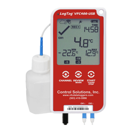
- Page 1 Control Solutions VFC400-USB Vaccine temperature monitoring Data Logger Product User Guide Document Release Version: 2.0 Published 1. October, 2021 Copyright © Control Solutions, 2018-2021 All rights reserved. www.vfcdataloggers.com...
-
Page 2: Table Of Contents
VFC400-USB User Guide Contents Safety Information Introduction Features Case Buttons Display and LED External Probes Power Supply What You Need Required Items Optional Items Preparing a VFC400-USB for first use In the Office On-site Inserting the Batteries Configuring the VFC400-USB for logging Finalizing the configuration Adding the Probes and the Power Supply Display Overview... - Page 3 Reviewing Day Statistics on the Display Stopping the VFC400-USB Plugging the VFC400-USB into a USB port Accessing the files Downloading the VFC400-USB to Control Solutions VTMC Re-deploying the VFC400-USB Interpreting the Data Data Evaluation - Report Data Evaluation - Data List...
-
Page 4: Safety Information
Empty batteries should be recycled or disposed of according to your local regulations. Liability Control Solutions’s standard warranty terms apply. A copy can be requested by emailing support@vfcdataloggers.com. In addition, Control Solutions shall not be held liable if the device was used beyond Control Solutions’s stated limitations;... - Page 5 Text in this font refers to option settings, dialogue boxes or actions to be taken in Control Solutions VTMC. Text describes features of the product. in this font This text describes certain aspects of the product, where incorrect use of a feature may lead to inadvertent loss of data.
-
Page 6: Introduction
USB port via a micro-USB cable. A PDF file is generated, which can be accessed using free PDF software such as Acrobat Reader. The VFC400-USB can also be downloaded to the free companion software Control Solutions VTMC, where you can display data in chart, list or summary formats. The software also allows electronic archiving and exporting to Control Solution Web Base VTMC (Vaccine Temperature Monitoring Cloud) for managing your region/clinical storage &... -
Page 7: Features
Features VFC400-USB User Guide Features The VFC400-USB Dual-channel temperature logger features a large display and USB connectivity with a familiar LogTag feel. Case Mounting lug for secure fastening of logger to fixtures Micro-USB socket with attached protective cap ... -
Page 8: Display And Led
29 days in the past. Details of any alarm event can be checked by inspecting the statistics history on the logger's display or in more detail via Control Solutions VTMC. In addition, a red Alarm LED shows if an alarm event has occurred. -
Page 9: What You Need
one or two external probes of the ST100 series a PC running Windows 7 SP1 or later and Control Solutions VTMC 3 installed if you wish to configure and download the logger a PC with PDF reader software installed for viewing the generated PDF files... - Page 10 What You Need VFC400-USB User Guide one or two glycol temperature buffers, which simulate environmental behavior of a vaccine vial...
-
Page 11: Preparing A Vfc400-Usb For First Use
These steps are completed in your office, using a PC connected to the internet: 1. Install the batteries into the unit. 2. Download and install the latest version of Control Solutions VTMC 3. You can do this from the Control Solutions Software Download page. -
Page 12: Inserting The Batteries
Preparing a VFC400-USB for first use VFC400-USB User Guide Inserting the Batteries The VFC400-USB operates with two AAA batteries: 1. Remove the screw from the rear compartment lid. 2. Remove the lid, exposing the battery compartment. 3. Insert the AAA batteries in the correct orientation, as shown. The polarity is marked inside the battery compartment. -
Page 13: Configuring The Vfc400-Usb For Logging
Preparing a VFC400-USB for first use VFC400-USB User Guide Configuring the VFC400-USB for logging Before a VFC400-USB logger can be deployed, it must be configured with the parameters required for starting and recording temperature values. Loggers can be purchased unconfigured, or pre-configured, ready to be started, using one of a number of different profiles that are available. - Page 14 printing the PDF; and triggering alarms. This is done using Control Solutions VTMC software, which can also be used for downloading and analyzing data: Start the Control Solutions VTMC software. Remove the protective cap from the logger's USB socket and plug the Micro USB end of the cable into the socket.
- Page 15 Figure 1: Standard configuration parameters for a VFC400-USB Adjust the settings as required. For detailed information about each parameter please read the section about Configuring a LogTag for logging in Control Solutions VTMC’s User Guide or press F1 for help.
- Page 16 Using pre-start readings is a good way to avoid data loss if you forget to start the unit, as you can still access the data using Control Solutions VTMC. Start delay If you configure the VFC400-USB to start after a delay period, the logger will not...
- Page 17 All alarm trigger conditions are entered in the Alarm Settings tab during configuration of the logger with Control Solutions VTMC. Alarms are configured separately for each channel. If you have chosen to log only one of the channels, the controls for the other channel are not available.
- Page 18 Preparing a VFC400-USB for first use VFC400-USB User Guide Once an alarm has triggered, the alarm indicator ( ) remains shown until the unit is reconfigured. The day alarm marker remains shown until midnight, then it turns off and the marker for the previous day is shown ( ) to indicate the alarm was registered against what is now the previous day.
- Page 19 Generating the data list For detailed information about each parameter please read the section about Configuring a LogTag for logging in Control Solutions VTMC’s User Guide or press F1 for help. The PDF file can not only be viewed in a PDF viewer, but can also be opened with...
- Page 20 START /CLEAR/STOP Enabling the three tone sounder for the audible alarm For detailed information about each parameter please read the section about Configuring a LogTag for logging in Control Solutions VTMC’s User Guide or press F1 for help.
-
Page 21: Finalizing The Configuration
Preparing a VFC400-USB for first use VFC400-USB User Guide Finalizing the configuration Click Configure to upload the configuration data to the VFC400-USB. When the configuration is complete, unplug the VFC400-USB from the USB socket and replace the protective seal. If you wish to configure more VFC400-USB units with the same configuration, insert the next loggers into USB sockets, wait until they are ready for configuration and click Repeat Configure. -
Page 22: Display Overview
Display Overview VFC400-USB User Guide Display Overview Following image shows the display with all segments turned on.* Day Alarm Markers * One rows of 7 markers, named Today ( ) to Day -6 ( ). A marker is switched on if an alarm event occurred on that day. - Page 23 Display Overview VFC400-USB User Guide CH1/CH2 Channel Identifiers * is shown when the data on the screen is representing data from the probe plugged into the socket marked CH1. Similarly, is shown for channel 2 data. Backup Battery Low A battery test is performed periodically. The battery low symbol will appear if the VFC400- USB's backup battery is low and requires changing.
- Page 24 Display Overview VFC400-USB User Guide The word is shown in Review mode, when the temperature on the display represents the maximum recorded temperature for the day displayed. The word is shown in Review mode, when the temperature on the display represents the minimum recorded temperature for the day displayed.
-
Page 25: Powering The Vfc400-Usb
Powering the VFC400-USB VFC400-USB User Guide Powering the VFC400-USB The VFC400-USB can be powered from one of two sources: Via two AAA batteries The batteries have a life span of approx. 6 to 12 months, depending on the quality of the battery, log interval, frequency of reviewing data on the display and how often an alarm sounds. -
Page 26: Low Power Operation
the display turns off after 30 seconds of inactivity, regardless of the setting made in Control Solutions VTMC; reviewing the data is not possible (however a mark will still be placed if the review button is pressed);... - Page 27 Powering the VFC400-USB VFC400-USB User Guide After pressing any button, following is shown on the display: The Recording state indicators, which show if the unit is recording, stopped, ready or configured for a delayed start Battery Empty symbol The internal secondary backup battery will power the logger's essential functions: ...
-
Page 28: Audible Alarm
This is enabled or disabled in the Advanced Settings when configuring the logger with Control Solutions VTMC. The alarm will sound once every four seconds for the first 24 hours, then sound less frequently to preserve battery life until the alarm is cleared, the unit stops or is re- configured. -
Page 29: Real-Time Clock
Each time the logger is configured with Control Solutions VTMC the display clock value is set to the PC's current local time (or timezone). - Page 30 Internally, the logger always retains its clock in UTC. You cannot adjust the clock beyond the allowed time zone limit of +15 hours and -12 hours from UTC (these are the same values you see as allowed time zone values in Control Solutions VTMC during configuration).
- Page 31 Real-Time Clock VFC400-USB User Guide If a display clock adjustment is made while recording data, the day summary page will contain a mark for each day on which the time was adjusted. Changes to the display clock do not affect the internal real time clock value, so the logged data does not show time gaps.
-
Page 32: Starting The Logger
Starting the Logger VFC400-USB User Guide Starting the Logger Push button start After configuration for a push button start the current time and are shown, together with READY Battery Status symbol. The power symbol is shown when the unit is connected to a USB power supply. -
Page 33: Push Button Start With Start Delay
Starting the Logger VFC400-USB User Guide you keep holding the button for more than 2 seconds after disappears; or READY the AAA batteries are critically low and the logger is not connected to power. Push Button Start with Start Delay If the logger has been configured for a push button start with a start delay, the word STARTING DELAY... -
Page 34: During Recording
During Recording VFC400-USB User Guide During Recording During normal operation, the display shows the most recently recorded temperature for channel 1 or channel 2. The channel for which the temperature is shown is indicated by the symbols The temperature on the display is updated when the logger takes a reading. The current time is also displayed (in 24 hour format). -
Page 35: Switching Channels On The Display
During Recording VFC400-USB User Guide The day marker for the current day ( ) is shown. The temperature has returned to within the At 1:49am on the next day accepted range (none of the alarm threshold the display shows the following: markers are visible), but the alarm remains present, as it has not been inspected and... - Page 36 During Recording VFC400-USB User Guide Auto Channel Swap starts again if you do not press this button for 30 seconds, or if you press the button. START /CLEAR/STOP The Alarm and OK symbols are independently shown for each channel. The red LED, however, blinks as long as either channel has registered an active alarm, and the buzzer will continue to operate.
- Page 37 During Recording VFC400-USB User Guide Day Alarm Matrix Display while recording During normal recording, symbols marked with are shown if an alarm occurred on that day. Today Day -1 ...
-
Page 38: Clearing An Alarm
During Recording VFC400-USB User Guide Clearing an Alarm During configuration with Control Solutions VTMC, you can allow users to clear an active alarm on the display. This is a useful function for an inspector, so repeated alarms can be recognized easier. -
Page 39: Paused Readings
The option is set in the Advanced Settings tab during configuration with Control Solutions VTMC and is expressed in number of readings after the last button press. Paused readings are specially marked in the graph and data listings. -
Page 40: Marking A Reading With An Inspection Mark
When evaluating data, any readings taken while the probe is disconnected are shown as --.- in the data list. The chart in Control Solutions VTMC will show a gap during this period. Minimum and Maximum values shown on the display will remain visible and will not be updated until the sensor is plugged back in. -
Page 41: Power Save
During Recording VFC400-USB User Guide Power Save When Power Save is enabled, the display will automatically switch off if none of the buttons have been pressed for 30 seconds, and the unit is operated by its AAA batteries. This function is appropriate in applications where you don't need to look at the display frequently, such as in transit monitoring applications, as the logger uses less battery power when the display is not turned on. -
Page 42: Clearing The Min/Max Values
You will be able to see on the PDF and in the summary in Control Solutions VTMC when the min/max values were cleared, but you will not be able to review previous min/max... -
Page 43: Reviewing Day Statistics On The Display
Reviewing Day Statistics on the Display VFC400-USB User Guide Reviewing Day Statistics on the Display Historic day statistics data can be accessed by repeatedly pressing the REVIEW /MARK button Each of the screens that follow shows: the day (relative to today), for which the data is being presented; ... - Page 44 Reviewing Day Statistics on the Display VFC400-USB User Guide Today's data Pressing the button displays the current day’s maximum statistic, in this case, the review starts with channel 1: The Today marker flashes to indicate that today's data is being displayed. ...
- Page 45 Reviewing Day Statistics on the Display VFC400-USB User Guide Pressing the button now displays yesterday’s minimum statistic: flashes, as we are still looking at yesterday's data. Yesterday, no temperature values were recorded below the lower alarm threshold. The alarm for the day was generated by the upper alarm, not by the lower alarm, so a...
- Page 46 Reviewing Day Statistics on the Display VFC400-USB User Guide Data from the day before yesterday Pressing the button now displays the maximum statistic from two days ago: flashes to indicate that the data being displayed is from two days ago. ...
- Page 47 Reviewing Day Statistics on the Display VFC400-USB User Guide Data from 7 days ago After pressing the button twice (skipping the minimum statistics for day -6) the maximum statistic from seven days ago is displayed: flashes to indicate that the data being displayed is from seven days ago.
- Page 48 Reviewing Day Statistics on the Display VFC400-USB User Guide Day Alarm Matrix Display while reviewing During review, symbols marked with are shown to indicate for which day review data is being displayed on screen. Today ...
-
Page 49: Stopping The Vfc400-Usb
Stopping the VFC400-USB VFC400-USB User Guide Stopping the VFC400-USB You can configure a VFC400-USB so it can be stopped with the button. START /CLEAR/STOP This feature is useful when you take the logger out of a shipment and don’t want to falsify the statistics with readings taken after the shipment completion. -
Page 50: Plugging The Vfc400-Usb Into A Usb Port
USB memory stick. These drivers will not be installed if the VFC400-USB does not generate files. USB Input Device (HID) Driver This device is used for communication to Control Solutions VTMC and its driver will always be installed, even if Control Solutions VTMC is not present on the computer. ... - Page 51 Plugging the VFC400-USB into a USB port VFC400-USB User Guide Once the files are generated, a new drive or mounted device will appear. The device name will be created from the serial number of the VFC400-USB. If you have disabled file generation during configuration, no drive will appear. USB communication can interfere with temperature measurement.
-
Page 52: Accessing The Files
If you have selected LTD as one of the file types, you will find a single file with the ltd extension, containing the data for both channels. To open the LTD file you need to install the free Control Solutions VTMC software. ... -
Page 53: Downloading The Vfc400-Usb To Control Solutions Vtmc
Once the unit is configured, continue the steps in the On-site section of the logger preparation. Control Solutions VTMC can be set up so these steps are automated. Please refer to the Control Solutions VTMC User Guide, specifically to the section about Automation. -
Page 54: Interpreting The Data
Interpreting the Data VFC400-USB User Guide Interpreting the Data The PDF contains the combined information for both channels. You will find two report pages, each with a chart; a single list (if configured), containing a column for each channel; and ... - Page 55 Interpreting the Data VFC400-USB User Guide File Information This section shows general information about the PDF file, such as generation time, date and time formats used in the chart and the data list as well as the file name, which is compiled from information about the data it contains: LogTag_[serial_number]_[trip number]_[file creation date]_file creation time]_[OK or ALM].pdf Other files that may be generated have the extensions *.csv and *.ltd.
- Page 56 Interpreting the Data VFC400-USB User Guide º symbol will be shown, if the VFC400-USB was downloaded with Control Solutions VTMC. • symbol will be shown if an inspection mark was placed with the REVIEW /MARK button. • symbol will be shown where a reading could not be taken due to USB communication with a PC.
-
Page 57: Data Evaluation - Data List
Interpreting the Data VFC400-USB User Guide Data Evaluation - Data List File Information The information from the report page is repeated here. Recorded Data list The Data list shows a single row for each recorded reading, along with the date, time and temperature values for each channel, plus any special events that were recorded against this reading. - Page 58 Interpreting the Data VFC400-USB User Guide Marked readings In the data list, each entry may be marked with one or more of the following symbols: A + symbol will be shown, if the VFC400-USB was downloaded with Control Solutions VTMC. ...
-
Page 59: Data Evaluation - Day Summary
Interpreting the Data VFC400-USB User Guide Data Evaluation - Day Summary For each channel, a separate day summary page is included in the PDF. File Information The information from the report page is repeated here. Day Summary The Day summary shows a single row for each day for which readings were recorded. Each row contains the following information: ... - Page 60 Interpreting the Data VFC400-USB User Guide If the clock was adjusted on one of the days, a special marker (*) will be displayed for that day. Page information The current page number and the total number of pages appear on every page.
-
Page 61: Resetting The Logger
This STOPPED means, the data from the previous trip is still accessible. The ability to reset a logger is enabled or disabled in the Advanced Settings tab when configuring the VFC400-USB via Control Solutions VTMC. -
Page 62: Hibernating A Vfc400-Usb
If you hibernate the logger for longer than a week, please remove the AAA batteries from the logger to avoid them leaking. VFC400-USB loggers are placed into Hibernation using Control Solutions VTMC by clicking Hibernate from the LogTag menu. Initially, the display shows SLP on the display until you remove the logger from the USB port. -
Page 63: Replacing The Batteries
Replacing the Batteries VFC400-USB User Guide Replacing the Batteries When the display shows that the battery is almost empty ( ) new batteries should be fitted. Open the case as described in Inserting the Batteries on page 12. Remove the old batteries and complete the remainder of the procedure. -
Page 64: Appendix 1 - Accuracy And Resolution
Appendix 1 - Accuracy and Resolution VFC400-USB User Guide Appendix 1 - Accuracy and Resolution Temperature Accuracy The following graph shows the typical rated temperature accuracy of a VFC400-USB, for either channel: Figure 6: Rated Temperature Accuracy Chart Temperature Resolution The following graph shows the typical rated native temperature resolution of a VFC400- USB, for either channel: Figure 7: Rated Temperature Resolution Chart... -
Page 65: Appendix 2 - Glossary
Appendix 2 - Glossary VFC400-USB User Guide Appendix 2 - Glossary Accumulative Alarm Temperature or humidity readings are above or below the configured threshold for the total of time defined, but readings may not necessarily be sequential. Active Alarm An Alarm/Alert that has triggered, but has not been cleared. Active Alert An Alarm/Alert that has triggered, but has not been cleared. - Page 66 Appendix 2 - Glossary VFC400-USB User Guide Alarm triggered One of the alarm trigger conditions has been met, the device displays an alert and the software reports an alarm event has taken place. Alert Visual or audible representation of an alarm on a device Consecutive Alarm Temperature or Humidity readings are above or below the configured threshold for the time defined without interruption.
- Page 67 Appendix 2 - Glossary VFC400-USB User Guide Lower Alarm Threshold If a recorded temperature or humidity value is equal to or below this value it is regarded to be an alarm reading. Non-Alarm Range Target temperature/humidity range where the readings are regarded as acceptable/within specification Non-Alert Range Target temperature/humidity range where the readings are regarded as acceptable/within...
- Page 68 Appendix 2 - Glossary VFC400-USB User Guide Upper Alarm Threshold If a recorded temperature or humidity value is equal to or above this value it is regarded to be an alarm reading.
Need help?
Do you have a question about the LogTag VFC400-USB and is the answer not in the manual?
Questions and answers