Advertisement
Quick Links
Advertisement

Related Manuals for Extreme Flight TURBO RAVEN EXP


Summary of Contents for Extreme Flight TURBO RAVEN EXP
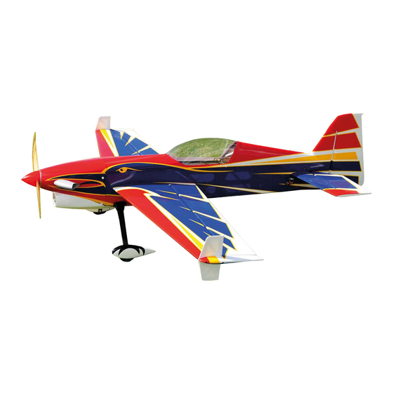
- Page 1 TURBO RAVEN 69 inch electric ARF assembly manual Copyright Extreme Flight 2019...
- Page 2 THIS IS NOT A TOY! Serious injury, destruction of property, or even death may result from the misuse of this product. Extreme Flight RC is providing you, the consumer, with a very high quality model aircraft component kit, from which you, the consumer, will assemble a flying model.
- Page 3 Greetings and congratulations on your purchase of the Extreme Flight RC 69 inch Turbo Raven EXP! This revolutionary new airframe designed by our good friend Cody Wojcik is insanely capable, precise, and pure feeling on just a 6S power system. This aircraft is...
- Page 4 Tips for Success: 1. Before starting assembly, take a few minutes to read the entire instruction manual to familiarize yourself with the assembly process. 2. Please take a few minutes and go over all the seams on the aircraft with a covering iron on a medium heat setting.
- Page 5 -4 high torque mini metal geared servos. All flight testing was performed with MKS 9767 and Savox 1260 servos. -Extreme Flight 1.25" lightweight servo arms (Qty 3) and 3" double arm with 2mm holes (Qty 1) -Torque 4016T/500 Brushless or Dualsky GA1500.5 Brushless Outrunner motor.
- Page 6 Let's begin! 1. Locate the 2 wing panels with ailerons as well as the 2 G10 aileron control horns and base plates. Remove the aileron and pull the hinges from the wing and aileron. Use Pacer Formula 560 Canopy Glue to secure the hinges.
- Page 8 CA. 3. Attach a 6" servo extension to your aileron servo and secure with an Extreme Flight Servo Safety Clip or a piece of heat shrink tubing. Secure the servo into the slot with the output spline facing the leading edge of the wing.
- Page 9 4. Locate the fuselage, carbon fiber main gear, wheel pants, fairings, wheels, axles and related hardware for mounting the landing gear. Use the provided mounting hardware to secure the main gear to the fuselage. Be sure to apply blue thread lock to the bolts before inserting into the gear and pre-installed blind nuts.
- Page 10 6. Glue the landing gear fairings into place against the fuselage side with silicon glue or medium CA applied to the carbon gear leg. 7. Secure the provided axles to the landing gear with a washer and nylon insert lock nut.
- Page 11 8. Slide the wheel onto the axle and secure with a wheel collar. Be sure to apply Blue Loctite to the set screw in the wheel collar. 9. Slide the wheel pants into position and secure with a 3mm bolt. You may need to open the slot in the wheel pant for proper fit over the axle.
- Page 12 10. Locate the rudder and rudder control horns and base plates. Trial fit the horns into position in their pre-cut slots and confirm alignment. Trace around the baseplate, and remove the covering under the baseplate. Glue the horns into position using 30 minute epoxy. Wipe away any excess epoxy with a paper towel soaked in denatured alcohol, re-confirm alignment and set aside to dry.
- Page 13 11. Mount the rudder servo in the rudder tray in the fuselage. Assemble the pull-pull cables as shown and secure to the servo arm and control horns with the provided 2mm hardware. The pull-pull cables should be crossed.
- Page 14 12. Install the tailwheel assembly as shown.
- Page 15 13. Locate the horizontal stab/elevator assembly. Remove the elevator from the stab. Insert the stab into the fuselage and the wing tube into its socket and confirm alignment. Glue the stab in place with a combination of thin and medium CA. 14.
- Page 16 17. Attach a 24" servo extension to the elevator servo and secure with an EF servo safety clip or heat shrink tubing. Install the elevator servo and assemble the linkage using an Extreme Flight 1.25" lightweight aluminum servo arm and the provided 2mm hardware as shown.
- Page 17 Dualsky G-1500.5 outrunner you will need to remove the radial mount and secure it to the motorbox first. 19.The Dualsky G-1500.5 motors that Extreme Flight supplies include 8mm standoffs that were specially made by Dualsky to get the total length of the motor to the same length as the Torque 4016/500. Use...
- Page 18 20. Install your choice of motor with the provided 4mm mounting bolts making sure to use a generous amount of Blue Loctite on each bolt. Mount the ESC on the bottom of the motor box and secure the motor wires to keep them from flapping around and getting chaffed. I used a piece of scrap foam padding to protect the ESC from vibration and secured the ESC with nylon cable ties.
- Page 19 22. Trim and glue the clear air scoop into the opening in the lower portion of the cowl with medium CA or Goop. 23. Cut 4 strips of masking tape from the roll. Place the strips onto the fuselage and mark the location of the blind nuts that are installed in the cowl mounting tabs with a felt tip pen.
- Page 20 24. Open the holes to accept the 3mm bolts and secure the cowl with 4 3mm bolts and washers. Be sure to apply a drop of Blue Loctite to each bolt. 25. Mount your choice of prop and the included Cyclone vented spinner.
- Page 21 26. Secure the SFGs and wing tips to the wing with 2 3mm bolts. 27. Slide the wing tube into the fuselage and slide the wings onto the tube. Secure with 2 3mm bolts and washers inserted through the wing retention tabs and into the pre-installed blind nuts. Use a drop of Blue Loctite on the bolts.
- Page 22 A huge thanks goes out to Cody Wojcik for all his work on this very unique aircraft. It is a joy and honor to have the Turbo Raven in our lineup and to be able to offer it to our customers. Enjoy! See ya at the flying field! Chris Hinson Extreme Flight...
Need help?
Do you have a question about the TURBO RAVEN EXP and is the answer not in the manual?
Questions and answers