Advertisement
Quick Links
Advertisement

Subscribe to Our Youtube Channel
Related Manuals for Extreme Flight Legacy Aviation Turbo Bushmaster


Summary of Contents for Extreme Flight Legacy Aviation Turbo Bushmaster
- Page 1 84” Turbo Bushmaster Copyright 2016 Extreme Flight...
- Page 2 ALL liability for the use of this product, please return it to the place of purchase immediately. Extreme Flight RC guarantees this kit to be free of defects in materials and workmanship for a period of 30 DAYS from the date of purchase.
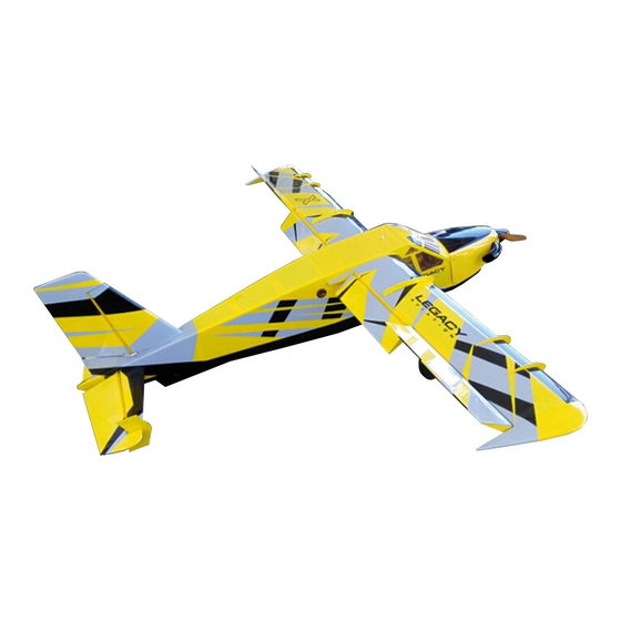
- Page 3 Congratulations on your purchase of the Legacy Aviation Turbo Bushmaster! Our intention with the Legacy line of aircraft is to provide unique sport-scale aircraft that are easy to assemble and fun to fly. These models possess gentle flight characteristics for the novice-to-intermediate sport flyer while also being capable of advanced aerobatics for the more experienced pilot.
-
Page 4: Let's Begin
Let’s begin! Wing Assembly Wing Hardware:... - Page 5 1. Locate the 2 wing panels as well as the composite aileron and flap control horns. Use sandpaper to scuff the portion of the control horn that will be glued into the surface. For a more finished look you may wish to paint your control horns before installation.
- Page 6 2. Using a soldering iron or a SHARP hobby knife, remove the covering from the slots for the aileron and flap horns. 3. Dry fit the horns into their respective slots and trim any debris from the slot until the control horn seats properly against the control surface.
- Page 7 5. Install the control horns into their respective slots and wipe away any excess epoxy with a paper towel or cloth soaked with denatured alcohol. 6. In these next steps we will install the hinges. Please take a few moments to familiarize yourself with this process if you have not installed hinge points before.
- Page 8 Locate a wing panel and separate the control surfaces from the main wing and remove the hinges. 8. Mix up a generous batch of epoxy and use a piece of pushrod or dowel to apply the epoxy to the hinge hole. 9.
- Page 9 10. Make sure the hinge can move freely and that the pin is aligned properly before the epoxy sets! When you are satisfied with the results set the surface aside so that the epoxy will pool around the rear of the hinge. When you are comfortable with this process you should be able to do one side of a surface per batch of epoxy.
- Page 10 12. You will need to attach a 12" servo extension to your aileron servo to reach the wing root. The flap servo wire will reach the root with no extension attached. Secure the extension to the servo lead with heat shrink tubing or a wire keep. 13.
- Page 11 14. Thread the supplied ball links onto each end of the 4 pushrods. Placing the pushrod into your electric drill and using it to thread the pushrod into the ball link makes this task much easier. Be very careful not to screw the pushrod in too far and damage the ball link! 15.
- Page 12 16. Locate the wing fences and trail fit on the wing. Some sanding may be required for best fit. While the fences are temporarily installed on the wing use 2 pieces of painters tape to mark their location on each side of the fence. This will aid in alignment and prevent excess glue from getting on the covering.
- Page 13 17. Use 30 min epoxy to attach the fences. Wipe away any excess epoxy with a paper towel soaked in acetone. Be sure to remove the tape before the epoxy fully cures. Repeat this process for the other wing panel.
- Page 14 Main Landing Gear Assembly and Installation Tools Required for this step 12mm Wrench 8mm Wrench or Nut Driver 2.5mm Hex Driver 1.5mm Hex Driver Thread locker Painters tape Sharp hobby knife Welders adhesive or Goop 18. Locate the landing gear fairings and black rubber tubing. You will need to slice the tubing lengthwise on one side.
- Page 15 19. Locate the carbon landing gear, axles, wheels and fasteners from the landing gear hardware package.
- Page 16 20. Attach the landing gear to the fuselage using the supplied bolts and washers. The landing gear has a slight airfoil, make sure that the thicker part of the gear is facing the nose of the airframe.
- Page 17 21. Slide the gear fairings into place against the bottom of the fuselage. Use a piece of painters to mark their location. Remove the fairing and apply a thick bead of Goop to the carbon gear just above the tape line. Slide the fairing back into place and secure with tape until dry.
- Page 18 22. Locate the 2 axles, 2 locking nuts, 2 wheels, 4 wheel collars and 2 washers and mount the wheels as shown.
- Page 19 Horizontal Stab and Elevator Assembly Stab/elevator Hardware kit...
- Page 20 23. Locate the horizontal stabilizer/elevator assembly. Turn it upside down on the building table and remove the covering from the control horn slot on the RIGHT side (This will be the Left side when installed). Glue the control horn in place with 30 minute epoxy. 24.
- Page 22 25. Now insert the horizontal stabilizer and check that the hinge holes match the holes in the elevator...
- Page 23 26. Check that the horizontal stabilizer is centered and properly aligned with the main wings. It is a good idea to use a tape measure and triple check all measurements before gluing the Stabilizer in place. Measure from a fixed point on the wings to the tip of the Stabilizer on both sides.
- Page 24 27. Once satisfied with the alignment, glue the horizontal stab in place by applying CA along the joint between the stab and the fuse. Make sure to apply CA to the top and bottom of the stab. 28. Once the horizontal stab is glued in place, use the same technique to install the elevator hinges and control horn that we used for the aileron and flaps.
- Page 26 29. Locate the fences for the horizontal stab and attach them with medium CA. Make sure to confirm alignment with the vertical stab.
- Page 27 30. Locate the lower keel. Note that the small extension piece (top piece in picture) is to be used when building the airframe for float flying only as it will occupy the space for the tailwheel. 31. Place the fuselage upside-down in a stand (the Extreme Flight 4-in-1 stand works great!).
- Page 28 32. Dry fit the lower keel in position and when happy with the fit, use 30-minute epoxy to attach it to the fuselage. Use tape to secure while drying. Be sure to check for proper alignment! 33. Attach an 18” servo extension to your elevator servo and using the manufacturer supplied hardware install it with the output shaft towards the rear of the fuselage.
- Page 29 Tailwheel Assembly 34. Gather the tools and parts required for this step A. 1.5 mm Hex Driver B. Phillips head screwdriver C. Thread locker D. Tail wheel E. Tail wheel axle F. Tail wheel Mounting Bracket G. Wheel Collar H. Tiller arm...
- Page 30 35. Attach the wheel to the Axle with the supplied wheel collar. NOTE: It is a good idea to file a small flat section on the axle for the wheel collar set screw to mate up to.
- Page 31 36. Next install the carbon fiber mounting bracket and tiller arm. Make sure to align the screw in the tiller arm with the flat spot on the tailwheel shaft and use thread lock!
- Page 32 Mounting the Tailwheel Assembly For this step you will need A. Assembled Tailwheel B. Small Phillips head screwdriver C. Thin CA D. 3 wood screws E. 5/64” Drill bit and Drill F. Tailwheel pushrod, Ball link and supplied hardware (not pictured...
- Page 33 37. Locate the Tailwheel pushrod (29.5” and threaded on one side) and insert it through the hole on the pilot’s upper left side and into the guide tube, threaded end first.
- Page 34 38. Push the control rod carefully until you feel resistance, locate the area where the control rod is trying to poke thru the covering and use a sharp hobby knife or soldering iron to remove the covering from this location. It is easiest to do this with the fuselage upside down in a stand.
- Page 35 Vertical Stab/ Rudder Assembly Rudder hardware kit...
- Page 36 o To mount the vertical stab and rudder you will need to locate the following: A. Vertical stab and rudder assembly B. Rear vertical stab wedge C. Carbon fiber vertical stab tube D. Rudder control horns E. 4mm cap head screw F.
- Page 37 40. Hinge the rudder using the same technique as the flaps and ailerons. Once the epoxy on the rudder hinges has cured, test fit the rudder control horns. Make sure to scuff the bases of the control horns. It may be necessary to trim the base of one of the control horns to ensure that both horns fit properly into the control horn slot.
- Page 38 42. When satisfied with the fit of the control horns, mix up a small batch of epoxy and install the rudder control horns. 43. Insert the carbon fiber vertical stab tube into the vertical stab/ rudder assembly. Then use your hobby knife or soldering iron to...
- Page 39 remove the covering from the right side of the vertical stab to reveal the mounting hole. 44. Slide the completed assembly into the vertical stab tube socket and secure the stab to the fuselage with a 4mm cap head screw. Don’t forget to use thread lock!
- Page 40 45. Deflect the rudder to one side and install the vertical stab wedge. Wick in a bit of CA to hold it in place.
- Page 41 46. Locate the servo you will be using for the rudder. Using the manufacturer supplied hardware mount the servo in the space provided on the battery tray and electronically center it. Note that the output shaft of the servo is towards the rear of the airframe.
- Page 42 48. Slide the Tailwheel pushrod into the EZ connector, center the tailwheel and tighten the cap screw. Make sure you use thread lock! 49. Next install the pull-pull cables and ball links. It is easiest to build the rear half (rudder side) of the cables and install them...
- Page 43 onto the rudder control horn, thread the cables thru the tubes in the rear of the fuselage and then build the front end of the cables on the servo side. To assemble the pull-pull linkage follow these steps: 1. Slide one of the aluminum crimps onto the braided wire. Insert the wire through the hole in the brass fitting and insert the end of the wire back through the crimp.
- Page 44 the cables so that there is no slack but do not make them guitar string tight as doing so can overstress the servo. Windscreen Installation 51. Next we'll install the windscreen. You have the choice of gluing the windscreen into place with a specialty glue like Pacer Formula 560...
- Page 45 canopy glue or sewing it on with screws (not included). Also, a pair of Lexan car body scissors will make this step much easier! 52. Locate the windscreen. Crudely trim it so that you can place it into position. 53. Use blue tape to mark a cut line with the tape being placed inside the line where you will trim the canopy.
- Page 47 Motor and Electronic Speed Control Installation 55. Locate the following and prepare the motor for mounting A. Motor (Torque 4016/500) B. ESC (Airboss 80A) C. Supplied Torque hardware kit with X mount and Bolt-on Prop Adapter D. 2.5mm Hex Driver E.
- Page 48 56. Secure the prop adapter to the motor with supplied socket head cap bolts using blue thread lock on each bolt.
- Page 49 Next slide the provided collar over the motor shaft and secure in place with the set screw. Place a small drop of thread lock on the threads of the set screw to prevent it from backing out. 58. Attach the Supplied X mount with the 4 Philips head screws. Again use a drop of thread lock on each screw.
- Page 50 59. Locate the 4mm black cap bolts and washers to attach the assembled motor to the firewall. 60. Using a drop of thread lock on each bolt attach the motor to the firewall.
- Page 51 61. Using a couple Zip ties and a scrap piece of foam mount the ESC to the bottom of the motor box. 62. Connect the wires of the ESC and the motor and secure them to the motor box with nylon cable ties. 63.
- Page 52 2 locations in the fuselage for mounting external ESC and BEC switches. If you are going to use a switch go ahead and mount it now.
- Page 53 Mounting the Cowl 64. Locate the following: A. Cowl B. Exhaust stacks C. Contact adhesive or Epoxy D. Sandpaper E. Painters tape F. Drill bit G. Felt tip pen...
- Page 54 65. Scuff the bottom of the exhaust stacks and the indentions on the cowl where they will mount.
- Page 55 66. Using contact adhesive or epoxy glue the exhaust stacks to the cowling and hold them in place with painter’s tape until the glue is dry.
- Page 56 67. When the glue for the exhaust stacks is fully cured, tear 4 short pieces of painter’s tape and place each piece of tape on the side of the fuselage so that each piece corresponds with one of the 4 cowl mounting tabs. Use a felt tipped pen to mark the location of the center of each mounting tab.
- Page 57 69. Remove the tape and cowl and add a drop of CA to each hole. Mount the cowl with the 4 of the small wood screws included with the kit.
- Page 58 70. Use a sharp hobby knife or soldering iron to remove the covering over the air escape holes in the bottom of the fuselage. 71. Mount your receiver as shown and tidy up the servo extensions. Pictured mounted to the battery tray are 2 multi- plug extensions to make plugging in your aileron/flap servo leads easier.
- Page 59 72. Install your prop and spinner.
- Page 60 73. Insert the carbon wing tube into the sleeve in the fuselage. Slide the wings into position taking care to insert the servo extensions into the fuselage. Secure the wings be inserting the nylon wing bolts into the holes in the fuselage and threading them into the blind nut in the wing root.
- Page 61 Cody Wojcik will cover various mixes to experiment with and will be posted on the Extreme Flight website. Thanks so much for your business and we hope you enjoy flying your Turbo Bushmaster as much as we have!
Need help?
Do you have a question about the Legacy Aviation Turbo Bushmaster and is the answer not in the manual?
Questions and answers