Advertisement
Quick Links
Advertisement

Subscribe to Our Youtube Channel
Related Manuals for Extreme Flight LASER EXP ARF


Summary of Contents for Extreme Flight LASER EXP ARF
-
Page 1: Instruction Manual
74” LASER EXP Instruction Manual Copyright 2014 Extreme Flight RC 1 ... - Page 2 THIS IS NOT A TOY! Serious injury, destruction of property, or even death may result from the misuse of this product. Extreme Flight RC is providing you, the consumer, with a very high quality model aircraft component kit, from which you, the consumer, will assemble a flying model.
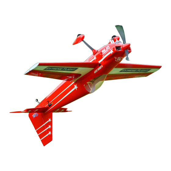
- Page 3 Congratulations on your purchase of the Extreme Flight RC 74 inch LASER EXP! This aircraft is unique in that it is being offered in two versions: A gas version and a dedicated electric version to satisfy the growing legions of electric power enthusiasts.
- Page 4 Items needed for completion: Masking tape. Hobby knife with #11 blades. Thin and medium CA. We highly recommend Mercury M5T thin and M100XF medium formulas as well as the Mercury glue tips. 30 minute epoxy. Mercury Adhesives Epoxies have worked very well for us. ...
- Page 5 Tips for Success: 1. Before starting assembly, take a few minutes to read the entire instruction manual to familiarize yourself with the assembly process. 2. Please take a few minutes and go over all the seams on the aircraft with a covering iron on a medium heat setting.
- Page 6 Let's begin! Elevator Assembly 1. Locate the horizontal stabilizer/elevator assemblies as well as the composite control horns and base plates from the elevator hardware package. Use a sharp #11 blade or soldering iron to remove the covering over the 2 slots for the elevator control horns on the bottom of the elevator surface.
- Page 7 3. Trace around the base plate with a felt tipped marker. 4. Remove the horn assembly and use a #11 blade to remove the covering from inside the ink line you traced around the control horn base. 7 ...
- Page 8 5. Wipe away the ink line with a cotton cloth or paper towel soaked in denatured alcohol. 6. Use sandpaper to scuff the portion of the horns and base plate that will be inserted into the elevator. 8 ...
- Page 9 7. Apply 30 minute epoxy to the elevator slots using a zip tie to ensure the slots are filled will epoxy. 8. Apply a generous amount of epoxy to the bottom of the G-10 control horns and base plate. 9 ...
- Page 10 9. Reinsert the assembly into the elevator and wipe away any excess epoxy with a cloth and denatured alcohol. Place a 3mm bolt through the horns to help insure proper alignment and set aside to dry. Repeat for the other elevator half. 10.
- Page 11 11. Use a cotton swab to apply petroleum jelly ONLY to the knuckle of the hinge. This will keep the epoxy from getting into the hinge which can cause it to bind. 12. Mix a generous batch of 30 minute epoxy. Use a zip tie or an old pushrod to thoroughly coat and fill the hinge holes on the stab with epoxy.
- Page 12 13. Next, coat one side of all 4 hinges with epoxy and push the hinges into the holes of the horizontal stab. Remember the short hinges go in the hole closest to the fuse. 14. Make sure the hinge pins are centered in the hinge gap and that they pivot 90 degrees to the stab.
- Page 13 15. Now coat the other side of the hinges as well as the hinge holes in the elevator with epoxy and install the elevator into the stab. Don’t forget to apply epoxy in the hinge holes on the stab before installing the stab to the elevator. 13 ...
- Page 14 16. Use denatured alcohol and a cloth to remove all excess epoxy, especially on the hinge pin. Make sure you have full deflection in both directions – once satisfied with the results, set the surface aside to dry. After the hinges have dried thoroughly, pull on them to make sure they are properly installed.
- Page 15 Wing Assembly 17. Locate the wing/aileron assemblies as well as the composite control horns and base plates from the wing hardware package. Following the same procedure as outlined with the elevator/stabs, install the control horns and hinges for both wings. Each wing has 5 hinges so it’s best to install the hinges in the aileron first then mix a second batch of epoxy to install the aileron hinges to the wing.
- Page 16 Note: Before moving to the next step – it would be a good time to seal the hinge gap with a strip of Ultracote or Blenderm tape. Be sure to fully deflect the control surface when sealing the gap to allow for full deflection once the gap is sealed. Also, take a few minutes to go over the wings with a trim iron on a medium heat to seal all the trim seams and remove any wrinkles in the covering.
- Page 17 18. Locate the aileron servo mount and remove the covering from this area. Use a sealing iron to seal the edges of the covering to the sides of the servo opening. Take a few minutes to apply some CA to the joints of the servo rails and the ribs. 19.
- Page 18 20. Locate and attach the 2 ball links onto the titanium turnbuckle pushrod. Secure the pushrod to the control horns and servo arm using the supplied 3mm bolts, washers, and nylon insert locknuts as shown in the picture below. As always, use blue Loctite on ALL bolts! 21.
- Page 19 Rudder and Tailwheel Assembly 22. Locate the rudder, the rudder control horns and the 2 slotted base plates. As with the elevators, use a sharp #11 blade to remove the covering from the 2 pre-cut slots in the rudder. 23. Temporarily install the control horns and base plates without epoxy. Ensure that the control horns center in the rudder properly.
- Page 20 24. Scuff both sides of the middle section of the horns between the reference marks made in the previous steps. Also scuff one side of both base plates as well. 25. Mix a generous batch of epoxy and completely fill the two slots as well as the areas on control horns and base plate that will glue into the rudder.
- Page 21 26. Slide the rudder horns back into their proper position. Clean the excess epoxy from the horns, and then install the base plates. 27. Carefully check alignment to insure proper positioning. Remove any excess epoxy from the rudder, re-check the alignment one more time and set the assembly aside to dry.
- Page 22 28. Locate a 2mm ball link from the hardware bag. Measure 3” back from the leading edge of the rudder and drill a hole to accept the shank on the ball link. Scuff the shaft of the ball link and glue it in the hole as shown in the picture below. 29.
- Page 23 30. Disassemble the tailwheel assembly and use a rotary tool or a small file to create a flat spot on the tailwheel wire for the set screws in the aluminum cap to seat against. Reassemble the unit and apply Loctite to the threads on the setscrews. Slide the tailwheel onto the wire and secure with the included wheel collars.
- Page 24 32. Install the rudder servo using the supplied hardware with the output shaft toward the rear of the plane. Also, install the recommended SWB 3.5” offset rudder arm and electrically center the servo. 33. Next, install the pull-pull rudder cables. Assemble one end of the linkage by inserting the pull-pull cable into one of the aluminum crimp tube, through the hole in the brass pull-pull fitting and back through the crimp tube.
- Page 25 34. Insert the bare end of the cable into the slot in the rear of the fuselage and feed it forward into the canopy area. Make the same type of linkage as done previously. Electronically center the servo and secure the linkage at both ends with a 3mm bolt and nylon insert lock nut.
- Page 26 Fuselage Assembly 35. Locate the Carbon Fiber main landing gear, 4 x 4mm bolts, lock nuts and washers. Place the gear onto the landing gear plate and align the 4 holes. Use a long allen wrench and insert the 4 x 4mm bolts from inside the fuse. Attach the 4 washers and lock nuts to each bolt and tighten.
- Page 27 36. Prepare the landing gear fairings by slitting the supplied black neoprene tubing length wise with a sharp hobby knife. Push the tubing onto the rim of the fairing and secure with CA. 27 ...
- Page 28 37. Temporarily slide the fairing onto the gear and up against the fuselage. Place some blue painters tape at the bottom of the fairing to mark the location on the gear. Lightly sand the gear leg where the fairing will attach. 38.
- Page 29 39. Once the silicon glue has thoroughly cured, remove the blue painters tape and clean up any residual glue using denatured alcohol. 40. Locate the 2 axles, 2 locking nuts, 2 washers, 2 wheels, 4 wheel collars and 2 wheel pants. Place the threaded portion of the axle through the hole in the landing gear, place a washer onto the axle and secure the axle with a locking nut.
- Page 30 41. Slide one wheel collar on the axel all the way to the base. Next, slide the wheel onto the axel and secure the wheel with the second wheel collar. Make sure the wheel is centered in the wheel pant. Repeat this process for the remaining wheel. 42.
- Page 31 43. Insert the blind nut inside the wheel pant as shown in the picture below. Apply a small amount of CA to hold the blind nut in place until the wheel pant is secured to the gear. 44. Secure the pant in position with the provided 3mm bolt and blind nut. As always, use blue Loctite on ALL bolts! Repeat this process for the remaining wheel pant.
- Page 32 45. Slide both stab/elevator assemblies onto the carbon fiber mounting tube and secure with 2 3mm bolts. Insert the bolts through a washer and the mounting tabs and into the corresponding blind nuts already installed in the fuselage. Apply blue Loctite to these bolts! 46.
- Page 33 47. Attach a 24" extension to each servo lead and install both elevator servos. Using the manufacturer supplied mounting hardware; mount both servos with the output shaft toward the rear of the fuselage as shown in the picture below. 48. Thread a ball link on each end of the steel pushrod and secure to the servo arm and elevator control horns with 2 x 3mm bolts, washers, and nylon insert locknut as shown in the picture below.
- Page 34 Next, install the motor/engine. The center and offset marks have been scribed into the front of the firewall with a laser. Use a mounting template and align with the marks on the firewall. Be sure to use the offset line to the right of the vertical center line to accommodate for the motor offset due to the built in right thrust angle in the motor box.
- Page 35 Desert Aircraft DA-35 with Pitts muffler mounted on the Laser. 51. Attach the top of the motor box using the 4 supplied wood screws. 35 ...
- Page 36 52. Tear 4 short pieces of blue painters tape from a roll. Place each piece of tape on the side of the fuselage so that each piece corresponds with one of the 4 cowl mounting tabs. Use a fine tipped marker to mark the location of the pre-drilled holes in the center of each mounting tab.
- Page 37 54. Remove the tape and secure the cowl with 4 x 3mm bolts and washers as shown in the picture below. Be sure to use a drop of blue Loctite on all bolts!!! This photo shows how we have cut the bottom of the cowl for engine and muffler clearance.
- Page 38 55. If you’re assembling the electric version, now is a good time to remove the covering on the bottom of the fuse just behind the turtle deck. This will allow an escape for the incoming air that cools the batteries. 56.
- Page 39 57. Also, included with your Laser EXP is a set of side force generators (SFGs). They are secured to each wingtip by inserting 2 x 3mm thumb bolts through the SFG, a clear plastic spacer, and into pre-installed blind nuts in each wing tip. 39 ...
- Page 40 Set-up and trimming The center of gravity range for the 74 inch Laser EXP begins at 5” from the leading edge of the wing measured at the root and extends back to 6”. CG is determined with the Laser in the upright position. One of the best ways to dial in the proper CG for your aircraft is the 45 degree line test.
- Page 41 Thanks again for your purchase of the Extreme Flight RC 74 inch Laser EXP ARF. I hope you enjoy assembling and flying yours as much as I have mine.
Need help?
Do you have a question about the LASER EXP ARF and is the answer not in the manual?
Questions and answers